
Subscribe to Our Youtube Channel
Related Manuals for Keysight Technologies E8740A


Summary of Contents for Keysight Technologies E8740A
- Page 1 Keysight E8740A Automotive Radar Signal Analysis and Signal Generation Installation & User Guide...
- Page 2 FAR 27.401 or DFAR could result in personal injury or death. 227.7103-5 (c), as applicable in any Do not proceed beyond a WARNING technical data. notice until the indicated conditions are fully understood and met. Keysight E8740A Automotive Radar Installation & User Guide...
- Page 3 The Mains wiring and connectors shall be compatible with the connector CAUTION used in the premise electrical system. Failure, to ensure adequate earth grounding by not using the correct components may cause product damage, and serious injury. Keysight E8740A Automotive Radar Installation & User Guide...
- Page 4 This product is designed for use in Installation Category II and Pollution CAUTION Degree 2 environment. Use the Keysight supplied power cord or one with the same or better electrical NOTE rating. Keysight E8740A Automotive Radar Installation & User Guide...
-
Page 5: Electrical Safety Compliance
Electrical Safety Compliance SAFETY Complies with European Low Voltage Directive 2014/35/EU – "IEC/EN 61010-1, 3rd Edition – "Canada: CAN/CSA C22.2 No. 61010-1-12 – "USA: ANSI/UL std no. 61010-1, 3rd Edition Keysight E8740A Automotive Radar Installation & User Guide... -
Page 6: Emi And Emc Compliance
During the warranty period, Keysight Technologies will, at its option, either repair or replace products that prove to be defective. For warranty service or repair, this product must be returned to a service facility designated by Keysight Technologies. -
Page 7: Where To Find The Latest Information
Is Your Product Software Up-to-Date? Keysight will periodically release software updates to fix known defects and incorporate product enhancements. To search for software updates for your product, go to the Keysight Software Manager website at: www.keysight.com/find/softwaremanager Keysight E8740A Automotive Radar Installation & User Guide... - Page 8 THIS PAGE HAS BEEN INTENTIONALLY LEFT BLANK. Keysight E8740A Automotive Radar Installation & User Guide...
-
Page 9: Table Of Contents
........63 User Guide Keysight E8740A Automotive Radar Installation & User Guide... - Page 10 ........148 Keysight E8740A Automotive Radar Installation & User Guide...
-
Page 11: Introduction
Keysight E8740A Automotive Radar Installation & User Guide Introduction Overview References... -
Page 12: Overview
Introduction Overview Welcome to the Installation and User Guide for the Keysight E8740A Automotive Radar test solutions. This guide provides basic steps for getting started as well as additional information. Installation of the SW components, loading and execution of the tests as well as basic hardware configurations will be covered. -
Page 13: References
Introduction References 1 KS8400A Test Automation Platform Developer's System https://www.keysight.com/en/pd-2747943-pn-KS8400A/ test-automation-platform-developers-system?cc=US&lc=eng 2 TAP Training: Introduction to using TAP https://www.keysight.com/upload/cmc_upload/All/ TAP_Training_1_GUI_Lab.pdf 3 Keysight VSA Software www.keysight.com/find/VSA 4 Keysight Signal Studio www.keysight.com/find/SignalStudio Keysight E8740A Automotive Radar Installation & User Guide... - Page 14 Introduction THIS PAGE HAS BEEN INTENTIONALLY LEFT BLANK. THIS PAGE HAS BEEN INTENTIONALLY LEFT BLANK. Keysight E8740A Automotive Radar Installation & User Guide...
-
Page 15: Hardware Configuration And Setup
Hardware Installation E8740A-010 Radar RF Signal Analysis E8740A-020 Basic Radar Signal Analysis E8740A-030 Basic Plus Radar Signal Analysis E8740A-040 Advanced Radar Signal Analysis E8740A-050 Advanced Plus Radar Signal Analysis E8740A-060 Performance Radar Signal Analysis... -
Page 16: Hardware Installation
Hardware Configuration and Setup Hardware Installation The Keysight E8740A test solution contains the following components of a scope, mixer, signal generator and software based on the configurations. The following are the configurations are available: – E8740A-010 Radar RF Signal Analysis –... -
Page 17: Setting Up Lan Connection With Instruments
Hardware Configuration and Setup Setting up LAN Connection with Instruments For all hardware configurations (from E8740A-010 to E8740A-090), a LAN connection can be established between instruments and the PC via an ethernet switch. 1 Launch Keysight Connection Expert. Click on Add and choose LAN Instrument. - Page 18 2 Enter the IP address or host name of the instrument. Click Test This VISA Address to determine if a connection has been established successfully. 3 If the connection is valid it will be verified. Keysight E8740A Automotive Radar Installation & User Guide...
- Page 19 4 The newly added instrument can be seen on the left pane of the Keysight Connection Expert window. If connecting instruments using USB there is no need to add the instruments NOTE manually. Keysight Connection Expert will automatically detects the newly added instruments. Keysight E8740A Automotive Radar Installation & User Guide...
-
Page 20: E8740A-010 Radar Rf Signal Analysis
Hardware Configuration and Setup E8740A-010 Radar RF Signal Analysis Keysight E8740A Automotive Radar Installation & User Guide... - Page 21 1.0 or later plugins Keysight License Manager 5.2 or later Keysight IO LIbraries 17.2 or later Refer to Chapter 3, "Software Installation, Configuration & Licensing" for more NOTE information on software installation and licensing. Keysight E8740A Automotive Radar Installation & User Guide...
- Page 22 Hardware Configuration and Setup The table below provides a close up view of the connections as shown in Figure 2-1. Hardware Connection LO/IF N9020B MXA Signal Analyzer M1971E Waveguide Harmonic Mixers LO/IF Keysight E8740A Automotive Radar Installation & User Guide...
-
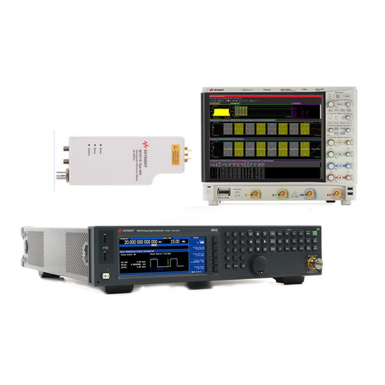
Page 23: E8740A-020 Basic Radar Signal Analysis
Hardware Configuration and Setup E8740A-020 Basic Radar Signal Analysis Keysight E8740A Automotive Radar Installation & User Guide... - Page 24 Hardware Configuration and Setup E8740A-020 Basic Radar Signal Analysis Figure 2-2 Keysight E8740A-020 Hardware requirement Hardware Description DSOS604A High-Definition Oscilloscope Oscilloscope N5183B MXG X-Series Microwave Signal Generator Analog Signal Generator M1971E Waveguide Harmonic Mixer Mixers Keysight E8740A Automotive Radar Installation & User Guide...
- Page 25 22.2 or later Keysight License Manager 5.2 or later Keysight IO LIbraries 17.2 or later Refer to Chapter 3, "Software Installation, Configuration & Licensing" for more NOTE information on software installation and licensing. Keysight E8740A Automotive Radar Installation & User Guide...
- Page 26 Hardware Configuration and Setup The table below provides a close up view of the connections as shown in Figure 2-2. Hardware Connection DSOS604A High-Definition Oscilloscope Keysight E8740A Automotive Radar Installation & User Guide...
- Page 27 Hardware Configuration and Setup Hardware Connection Front side: N5183B MXG X-Series Microwave Analog Signal Generator Rear side: M1971E Waveguide Harmonic Mixers LO/IF Keysight E8740A Automotive Radar Installation & User Guide...
-
Page 28: E8740A-030 Basic Plus Radar Signal Analysis
Hardware Configuration and Setup E8740A-030 Basic Plus Radar Signal Analysis Keysight E8740A Automotive Radar Installation & User Guide... - Page 29 E8740A-030 Basic Plus Radar Signal Analysis Figure 2-3 Keysight E8740A-030 Hardware requirement Hardware Description DSOS604A High-Definition Oscilloscope Oscilloscope N5183B MXG X-Series Microwave Signal Generator Analog Signal Generator N9029AV12 Millimeter-Wave Signal Mixer Analyzer Frequency Extension Module Keysight E8740A Automotive Radar Installation & User Guide...
- Page 30 22.2 or later Keysight License Manager 5.2 or later Keysight IO LIbraries 17.2 or later Refer to Chapter 3, "Software Installation, Configuration & Licensing" for more NOTE information on software installation and licensing. Keysight E8740A Automotive Radar Installation & User Guide...
- Page 31 The table below provides a close up view of the connections as shown in Figure 2-3. Hardware Connection DSOS604A High-Definition Oscilloscope Front side: N5183B MXG X-Series Microwave Analog Signal Rear side: Generator N9029AV12 Millimeter-Wave Signal Analyzer Frequency Extension Module Keysight E8740A Automotive Radar Installation & User Guide...
-
Page 32: E8740A-040 Advanced Radar Signal Analysis
Hardware Configuration and Setup E8740A-040 Advanced Radar Signal Analysis Keysight E8740A Automotive Radar Installation & User Guide... - Page 33 Hardware Configuration and Setup E8740A-040 Advanced Radar Signal Analysis Figure 2-4 Keysight E8740A-040 Hardware requirement Hardware Description DSOS604A High-Definition Oscilloscope Oscilloscope Signal Analyzer N9020B MXA Signal Analyzer M1971E Waveguide Harmonic Mixer Mixers Keysight E8740A Automotive Radar Installation & User Guide...
- Page 34 22.2 or later Keysight License Manager 5.2 or later Keysight IO LIbraries 17.2 or later Refer to Chapter 3, "Software Installation, Configuration & Licensing" for more NOTE information on software installation and licensing. Keysight E8740A Automotive Radar Installation & User Guide...
- Page 35 The table below provides a close up view of the connections as shown in Figure 2-4. Hardware Connection DSOS604A High-Definition Oscilloscope IF In LO/IF N9020B MXA Signal Analyzer M1971E Waveguide Harmonic Mixers LO/IF Keysight E8740A Automotive Radar Installation & User Guide...
-
Page 36: E8740A-050 Advanced Plus Radar Signal Analysis
Hardware Configuration and Setup E8740A-050 Advanced Plus Radar Signal Analysis Keysight E8740A Automotive Radar Installation & User Guide... - Page 37 N9029AV12 Millimeter-Wave Signal Mixer Analyzer Frequency Extension Module Software requirement Software Version KS8400A Test Automation 8.8 or later Platform KS83200A Automotive Radar 1.0 or later plugins 89600 Keysight VSA Software 22.2 or later Keysight E8740A Automotive Radar Installation & User Guide...
- Page 38 The table below provides a close up view of the connections as shown in Figure 2-5. Hardware Connection DSOS604A High-Definition Oscilloscope IF In (MXA) LO/IF N9020B MXA Signal Analyzer Keysight E8740A Automotive Radar Installation & User Guide...
- Page 39 Hardware Configuration and Setup Hardware Connection Front side: N5183B MXG X-Series Microwave Analog Signal Rear side: Generator N9029AV12 Millimeter-Wave Signal Analyzer Frequency Extension Module Keysight E8740A Automotive Radar Installation & User Guide...
-
Page 40: E8740A-060 Performance Radar Signal Analysis
Hardware Configuration and Setup E8740A-060 Performance Radar Signal Analysis Keysight E8740A Automotive Radar Installation & User Guide... - Page 41 Hardware Configuration and Setup E8740A-060 Performance Radar Signal Analysis Figure 2-6 Keysight E8740A-060 Hardware requirement Hardware Description DSOS804A High-Definition Oscilloscope Oscilloscope Signal Analyzer N9041B UXA Signal Analyzer Keysight E8740A Automotive Radar Installation & User Guide...
- Page 42 5.2 or later Keysight IO LIbraries 17.2 or later FMCW Radar Assistant 22.3 or later Refer to Chapter 3, "Software Installation, Configuration & Licensing" for more NOTE information on software installation and licensing. Keysight E8740A Automotive Radar Installation & User Guide...
- Page 43 Hardware Configuration and Setup The table below provides a close up view of the connections as shown in Figure 2-6. Hardware Connection DSOS804A High-Definition Oscilloscope Wideband IF output N9041B UXA Signal Analyzer RF Input Keysight E8740A Automotive Radar Installation & User Guide...
-
Page 44: E8740A-070 Performance Radar Signal Generation
Hardware Configuration and Setup E8740A-070 Performance Radar Signal Generation Keysight E8740A Automotive Radar Installation & User Guide... - Page 45 N9029ACST-U12 Millimeter-Wave Mixer Signal Analyzer Frequency Extension Module Software requirement Software Version KS8400A Test Automation 8.8 or later Platform KS83200A Automotive Radar 1.0 or later plugins N7608APPC Keysight Signal 1.2 or later Studio Keysight E8740A Automotive Radar Installation & User Guide...
- Page 46 NOTE information on software installation and licensing. The table below provides a close up view of the connections as shown in Figure 2-7. Hardware Connection M8195A 65 GSa/s Arbitrary Waveform Generator Keysight E8740A Automotive Radar Installation & User Guide...
- Page 47 Hardware Configuration and Setup Hardware Connection Front side: Right N5183B MXG X-Series Microwave Analog Signal Generator N9029ACST-U12 Millimeter-Wave Signal Analyzer Frequency Extension Module Keysight E8740A Automotive Radar Installation & User Guide...
-
Page 48: E8740A-080 Interference Test Solution
Hardware Configuration and Setup E8740A-080 Interference Test Solution Keysight E8740A Automotive Radar Installation & User Guide... - Page 49 N5183B MXG X-Series Microwave Signal Generator Analog Signal Generator N9029ACST-U12 Millimeter-Wave Mixer Signal Analyzer Frequency Extension Module Radar Simulator E8708A Radar Target Simulator N1913A EPM Series Single-Channel Power Meter Power Meter Millimeter-wave programmable Attenuator attenuator Keysight E8740A Automotive Radar Installation & User Guide...
- Page 50 Keysight IO LIbraries 17.2 or later M8195A Firmware and Soft Front 3.6 or later Panel Refer to Chapter 3, "Software Installation, Configuration & Licensing" for more NOTE information on software installation and licensing. Keysight E8740A Automotive Radar Installation & User Guide...
- Page 51 The table below provides a close up view of the connections as shown in Figure 2-8. Hardware Connection M8195A 65 GSa/s Arbitrary Waveform Generator Left Right N5183B MXG X-Series Microwave Analog Signal Generator Keysight E8740A Automotive Radar Installation & User Guide...
- Page 52 Hardware Configuration and Setup Hardware Connection N9029ACST-U12 Millimeter-Wave Signal Analyzer Frequency Extension Module E8708A Radar Target Simulator To DUT Keysight E8740A Automotive Radar Installation & User Guide...
-
Page 53: E8740A-090 Conformance Spurious Emission Test Solution
Hardware Configuration and Setup E8740A-090 Conformance Spurious Emission Test Solution Keysight E8740A Automotive Radar Installation & User Guide... - Page 54 - N9029AV03 Millimeter-Wave Signal Analyzer Frequency Extension Module - N9029AV05 Millimeter-Wave Signal Analyzer Frequency Extension Module Mixer - N9029AV08 Millimeter-Wave Signal Analyzer Frequency Extension Module - N9029AV12 Millimeter-Wave Signal Analyzer Frequency Extension Module Keysight E8740A Automotive Radar Installation & User Guide...
- Page 55 40 GHz - 60 GHz RF Port 2 60 GHz - 90 GHz Switch 1 Port 1 90 GHz - 140 GHz Switch 1 Port 2 140 GHz - 220 GHz Switch 1 Port 3 Keysight E8740A Automotive Radar Installation & User Guide...
- Page 56 Hardware Configuration and Setup Hardware Connection 220 GHz - 330 GHz Switch 1 Port 4 U1816C Coaxial Switch LO/ IF N9029AV12 Millimeter-Wave Signal Analyzer Frequency Extension Module Keysight E8740A Automotive Radar Installation & User Guide...
-
Page 57: Software Installation, Configuration & Licensing Software Installation
Keysight E8740A Automotive Radar Installation & User Guide Software Installation, Configuration & Licensing The information presented in this chapter might differ from the current software NOTE due to new releases, upgrades and/or fixes in software. Software Installation Software Components Compatibility... - Page 58 Software Installation, Configuration & Licensing Software Installation The SW components required for the E8740A Automotive Radar are installed separately. Please install the components in the following order: 1 Install the TAP Development System application. Installation steps can be found in the "Installing TAP" section of...
- Page 59 Refer to “Licensing” on page 62 for more information on the different Automotive NOTE Radar licenses available (KS83200A, KS83RX0A and KS83ST0A.) Keysight E8740A Automotive Radar Installation & User Guide...
-
Page 60: Software Components Compatibility
Software component HW 010 HW 020 HW 030 HW 040 HW 050 HW 060 HW 070 HW 080 HW 090 KS8400A TAP Platform Keysight N7608C Signal Studio 89600 Keysight VSA Software No KS83200A Keysight E8740A Automotive Radar Installation & User Guide... - Page 61 M8195A Firmware and Soft Front Panel Refer to “Licensing” on page 62 for more information on KS83200A, KS83RX0A NOTE and KS83ST0A. 89600 Keysight VSA Software refers to both 89601B-200 and 89601B-BHP. NOTE Keysight E8740A Automotive Radar Installation & User Guide...
-
Page 62: Licensing
Automation platform for Automotive Radar - enables tests according to ETSI KS83ST0A standard. Optional and apllicable for E8740A 010, 040, 050, 060, 070, 080 and 090. The license status of the TAP Plugins can be seen using the TAP Plugin manager:... -
Page 63: Installing Licenses
Once the license is purchased, it can be installed in your PC using Keysight License Manager. 1 Launch Keysight License Manager. Click on the highlighted icon on the top right corner. 2 Select Install License File. Keysight E8740A Automotive Radar Installation & User Guide... - Page 64 Software Installation, Configuration & Licensing 3 Choose the license file that you want to install. Click Open, and the license will be installed. Keysight E8740A Automotive Radar Installation & User Guide...
-
Page 65: User Guide
The information presented in this chapter might differ from the current software NOTE due to new releases, upgrades and/or fixes in software. Introduction Basic Test Plug-in ETSI Standards Plug-in Corrections/ Calibrations for ETSI Tx and Rx Test Cases Report Generation for ETSI Tx Test Cases E8740A-090 Conformance Spurious Emission Test Solution... -
Page 66: Basic Test Plug-In
User Guide Basic Test Plug-in Keysight E8740A Automotive Radar Installation & User Guide... - Page 67 KS83200A - Basic Test Plug-in License KS83RX0A - Rx and Interference Testing License (optional) KS83ST0A - ETSI Standards Testing License (optional) For more details on licensing refer to “Licensing” on page 62. Keysight E8740A Automotive Radar Installation & User Guide...
- Page 68 User Guide Figure 4-1 Basic tests The 3 main test groups under Basic Feature - Signal Analysis, Signal Generation and Signal Quality Measurement. Keysight E8740A Automotive Radar Installation & User Guide...
-
Page 69: Signal Analysis
The channel power measurement is made on the RF input signal after frequency down conversion and an analog to digital conversion. The actual power measurement is performed by the test set's digital signal processor (DSP). Figure 4-2 Channel power Keysight E8740A Automotive Radar Installation & User Guide... - Page 70 — Frequency Range 90 GHz 90 GHz 90 GHz — Antenna Gain 0 dBi 0 dBi 0 dBi 0 dBi 0 dBi 0 dBi — IF Center Frequency 3 GHz 3 GHz 3 GHz Keysight E8740A Automotive Radar Installation & User Guide...
- Page 71 — Antenna Gain — IF Center Frequency Down Converter LO Source Setting — LO Source — Frequency — Amplitude Keysight E8740A Automotive Radar Installation & User Guide...
- Page 72 During this measurement, a Gaussian filter with a bandwidth greater than 10 MHz and a resolution bandwidth (RBW) of 30 kHz or less is used to measure the distribution of the power spectrum. Figure 4-3 Occupied bandwidth Keysight E8740A Automotive Radar Installation & User Guide...
- Page 73 1 MHz 1 MHz 1 MHz 1 MHz 1 MHz Display Mode Hold Hold Hold Detector Mode Average Average Average N/A Measurement Setting — IF Center Frequency 3 GHz 3 GHz 3 GHz Keysight E8740A Automotive Radar Installation & User Guide...
- Page 74 Measurement Setting — Frequency Range — IF Center Frequency Down Converter LO Source Setting — LO Source — Frequency — Amplitude Keysight E8740A Automotive Radar Installation & User Guide...
-
Page 75: Signal Generation
There are 4 options under Signal Generation: Continuous Wave, Custom Chirp Signal, FMCW Up/Symm/Down and MFSK. Continuous Wave A continuous wave or continuous waveform (CW) is an electromagnetic wave of constant amplitude and frequency. Figure 4-4 Continuous Wave Keysight E8740A Automotive Radar Installation & User Guide... - Page 76 — Sample rate (GSa/s) 64 GSa/s 64 GSa/s — Amplitude 0 dBm — Waveform Frequency 77 GHz 77 GHz — Channel 1 — Channel 2 Keysight E8740A Automotive Radar Installation & User Guide...
- Page 77 — Channel 1 — Channel 2 — Channel 3 — Channel 4 Up Converter LO Source Setting — LO Source Keysight E8740A Automotive Radar Installation & User Guide...
- Page 78 User Guide Parameter Config Config Config Config Config Config Config Config Config — Frequency — Amplitude Keysight E8740A Automotive Radar Installation & User Guide...
- Page 79 — Feature Range AWG Waveform Property — AWG Generator — Sample rate (GSa/s) 64 GSa/s 64 GSa/s — Amplitude 0 dBm 0 dBm — Waveform Frequency 77 GHz 77 GHz Keysight E8740A Automotive Radar Installation & User Guide...
- Page 80 AWG Waveform Property — AWG Generator — Sample rate (GSa/s) — Amplitude — Waveform Frequency — Channel 1 — Customize Chirp Setting Keysight E8740A Automotive Radar Installation & User Guide...
- Page 81 — No. of Segment — Total Sweep Time — Chirp List Up Converter LO Source Setting — LO Source — Frequency — Amplitude Keysight E8740A Automotive Radar Installation & User Guide...
- Page 82 User Guide FMCW - Up/Symm/Down FMCW is Frequency-Modulated Continuous Wave. FMCW method continuously measures a mixed differential frequency. Figure 4-6 FMCW Up/Symm/Down Click Add (Basic Feature> Signal Generation> FMCW - Up/Symm/Down) Keysight E8740A Automotive Radar Installation & User Guide...
- Page 83 60 GHz - 90 GHz 60 GHz - 90 GHz AWG Waveform Property — AWG Generator — Sample rate (GSa/s) 64 GSa/s 64 GSa/s — Amplitude 0 dBm 0 dBm Keysight E8740A Automotive Radar Installation & User Guide...
- Page 84 Setup". Parameter Config Config Config Config Config Config Config Config Config Feature Range — Feature Range AWG Waveform Property — AWG Generator — Sample rate (GSa/s) Keysight E8740A Automotive Radar Installation & User Guide...
- Page 85 — Chirp Type — Sweep Time FMCW Setting — Bandwidth Up Converter LO Source Setting — LO Source — Frequency — Amplitude Keysight E8740A Automotive Radar Installation & User Guide...
- Page 86 MFSK is similar to frequency shift keying (FSK), but more than two frequencies are used. Figure 4-7 MFSK Keysight E8740A Automotive Radar Installation & User Guide...
- Page 87 The table below shows the allowable values based on hardware configuration. HW 070 HW 080 Parameter Config Config Feature Range 60 GHz - 90 60 GHz - 90 — Feature Range AWG Waveform Property — AWG Generator Keysight E8740A Automotive Radar Installation & User Guide...
- Page 88 Setup". Parameter Config Config Config Config Config Config Config Config Config Feature Range — Feature Range AWG Waveform Property — AWG Generator — Sample rate (GSa/s) Keysight E8740A Automotive Radar Installation & User Guide...
- Page 89 — Step Frequency — Step Time — Number of Step Up Converter LO Source Setting — LO Source — Frequency — Amplitude Keysight E8740A Automotive Radar Installation & User Guide...
-
Page 90: Signal Quality Measurement
“ideal” modulated signal in the signal and the frequency domains. FMCW Signal Quality can be found under this option. Figure 4-8 FMCW Signal Quality Click Add (Basic Feature> Signal Quality Measurement> FMCW Signal Quality) Keysight E8740A Automotive Radar Installation & User Guide... - Page 91 — Acquisition Length 1 ms 1 ms 1 ms 1 ms — Minimum Region Time 2 us 2 us 2 us 2 us Length — Minimum Region Time Count Down Converter LO Source Setting Keysight E8740A Automotive Radar Installation & User Guide...
- Page 92 Length — Minimum Region Time Count Down Converter LO Source Setting — LO Source — Frequency — Amplitude Keysight E8740A Automotive Radar Installation & User Guide...
-
Page 93: Etsi Standards Plug-In
User Guide ETSI Standards Plug-in Keysight E8740A Automotive Radar Installation & User Guide... - Page 94 TAP Platform KS83200A - Basic Test Plug-in License KS83ST0A - ETSI Standards Testing License KS83RX0A - Rx and Interference Testing License (optional) For more details on licensing refer to “Licensing” on page 62. Keysight E8740A Automotive Radar Installation & User Guide...
-
Page 95: Etsi Standards
(TTT); Short Range Radar equipment operating in the 77 GHz to 81 GHz band; Harmonised Standard covering the essential requirements of article 3.2 of Directive 2014/53/EU. For further information regarding ETSI standards, visit www.etsi.org/standards. Keysight E8740A Automotive Radar Installation & User Guide... - Page 96 User Guide The ETSI plug-ins are divided into Transmitter Conformance and Receiver Conformance sections. Figure 4-9 ETSI plug-ins Keysight E8740A Automotive Radar Installation & User Guide...
- Page 97 Test Step Settings. This allows the user to choose the Hardware Configuration, refer the Connections Setup Diagram, choose the ETSI Specifications as well as change the necessary parameters required for testing. Keysight E8740A Automotive Radar Installation & User Guide...
-
Page 98: Transmitter Conformance
The interpretation of the results for the measurement uncertainty shall be as given in clause 4.6 of ETSI EN 303 396 [1]. The Transmitter Conformance consists of Operating Frequency Range, Mean Power, Peak Power, Unwanted Emissions in the Out-of-Band Domain. Keysight E8740A Automotive Radar Installation & User Guide... - Page 99 4 ms 4 ms 4 ms Video Bandwidth 3 MHz 3 MHz 3 MHz Frequency Upper Limit 77 GHz 81 GHz 24.5 GHz Frequency Lower Limit 76 GHz 77 GHz 24.0 GHz Keysight E8740A Automotive Radar Installation & User Guide...
- Page 100 Down Converter LO Source Setting — LO Source — Frequency — Amplitude Correction — Enable Correction Measurement Setting — IF Center Frequency Keysight E8740A Automotive Radar Installation & User Guide...
- Page 101 User Guide Parameter Config Config Config Config Config Config Config Config Config Pass/Fail Limit — Upper Limit — Lower Limit Keysight E8740A Automotive Radar Installation & User Guide...
- Page 102 79 GHz Frequency Span 2.5 GHz 9 GHz Video Bandwidth 3 MHz 3 MHz Resolution Bandwidth 1 MHz 1 MHz Integration Bandwidth 1 GHz 1 GHz Sweep Time 4 ms 4 ms Keysight E8740A Automotive Radar Installation & User Guide...
- Page 103 RF Signal Path Setting — RF Port 1 — RF Port 2 — RF Port Switch Down Converter LO Source Setting — LO Source — Frequency Keysight E8740A Automotive Radar Installation & User Guide...
- Page 104 Config Config Config — Amplitude Correction — Enable Correction Measurement Setting — IF Center Frequency Pass/Fail Limit — Upper Limit Keysight E8740A Automotive Radar Installation & User Guide...
- Page 105 User Guide Peak Power The radiated peak power (e.i.r.p.) is the highest instantaneous power radiated by the equipment. It is measured in the permitted range of operating frequencies. Figure 4-12 Peak Power Keysight E8740A Automotive Radar Installation & User Guide...
- Page 106 Resolution Bandwidth 1 MHz 1 MHz 1 MHz Integration Bandwidth 1 GHz 1 GHz 1 GHz Sweep Time 4 ms 4 ms 4 ms Display Mode Max Hold Max Hold Max Hold Keysight E8740A Automotive Radar Installation & User Guide...
- Page 107 — Video Bandwidth — Resolution Bandwidth — Integration Bandwidth — Sweep Time Keysight E8740A Automotive Radar Installation & User Guide...
- Page 108 — Frequency — Amplitude Correction — Enable Correction Measurement Setting — IF Center Frequency Pass/Fail Limit — Upper Limit Keysight E8740A Automotive Radar Installation & User Guide...
- Page 109 Out of band emissions are emissions on a frequency or frequencies immediately outside the necessary bandwidth which results from the modulation process, but excluding spurious emissions. Figure 4-13 Unwanted emission in the out of band domain Keysight E8740A Automotive Radar Installation & User Guide...
- Page 110 1 GHz 1 GHz 1 GHz Sweep Time 4 ms 4 ms 4 ms Display Mode Clear/Write Clear/Write Clear/Write Detector Mode Average Average Average Upper Limit 0 dBm 0 dBm 10 dBm Keysight E8740A Automotive Radar Installation & User Guide...
- Page 111 — RF Port Switch Down Converter LO Source Setting — LO Source — Frequency — Amplitude Correction — Enable Correction Measurement Setting Keysight E8740A Automotive Radar Installation & User Guide...
- Page 112 User Guide Parameter Config Config Config Config Config Config Config Config Config — IF Center Frequency Pass/Fail Limit — Upper Limit Keysight E8740A Automotive Radar Installation & User Guide...
- Page 113 Refer to the table below for standard values according to ETSI standards. HW 090 Parameter Config Start Frequency 0 Hz Stop Frequency 330 GHz Video Bandwidth 3 MHz Resolution Bandwidth 1 MHz Sweep Time 2 ms Keysight E8740A Automotive Radar Installation & User Guide...
- Page 114 — Resolution Bandwidth — Sweep Time — Display Mode — Detector Mode Pass/ Fail Limit — No. of Range — Emission Limit Setting Correction — Enable Correction Keysight E8740A Automotive Radar Installation & User Guide...
-
Page 115: Receiver Conformance
3.1(b) and 3.2 of the Directive 2014/53/EU [i.3]. Essential requirements are high level objectives described in European Directives. The purpose of the Harmonised Standard is to translate those high level objectives into detailed technical specifications. Keysight E8740A Automotive Radar Installation & User Guide... - Page 116 Figure 4-15 Receiver spurious emission Refer to the table below for standard values according to ETSI standards. HW 090 Parameter Config Start Frequency 0 Hz Stop Frequency 330 GHz Video Bandwidth 3 MHz Keysight E8740A Automotive Radar Installation & User Guide...
- Page 117 — Resolution Bandwidth — Sweep Time — Display Mode — Detector Mode Pass/ Fail Limit — No. of Range — Emission Limit Setting Correction — Enable Correction Keysight E8740A Automotive Radar Installation & User Guide...
- Page 118 Parameter Config Config Config Config Config Config Config Config Config AWG Waveform Property — AWG Generator — Channel 1 Signal Parameters — Selected Frequency Keysight E8740A Automotive Radar Installation & User Guide...
- Page 119 — EIRP at DUT — Free Space Path Loss — Final Output Power Up Converter LO Source Setting — LO Source — Amplitude Keysight E8740A Automotive Radar Installation & User Guide...
- Page 120 Chapter 2, "Hardware Configuration and Setup". Parameter Config Config Config Config Config Config Config Config Config AWG Waveform Property — AWG Generator — Channel 1 Signal Parameters Keysight E8740A Automotive Radar Installation & User Guide...
- Page 121 — EIRP at DUT — Free Space Path Loss — Final Output Power Up Converter LO Source Setting — LO Source — Amplitude (dBm) Keysight E8740A Automotive Radar Installation & User Guide...
- Page 122 Chapter 2, "Hardware Configuration and Setup". Parameter Config Config Config Config Config Config Config Config Config AWG Waveform Property — AWG Generator — Channel 1 Signal Parameters Keysight E8740A Automotive Radar Installation & User Guide...
- Page 123 — EIRP at DUT — Free Space Path Loss — Final Output Power Up Converter LO Source Setting — LO Source — Amplitude Keysight E8740A Automotive Radar Installation & User Guide...
- Page 124 User Guide Correction/ Calibrations for ETSI Tx and Rx Test Cases Keysight E8740A Automotive Radar Installation & User Guide...
-
Page 125: Corrections/ Calibrations For Etsi Tx And Rx Test Cases
– Automotive Radar test app will set all corrections to be on in SA – SA will look into the Corrections database, check which corrections are on and will be automatically applied. Keysight E8740A Automotive Radar Installation & User Guide... - Page 126 Corrections help to compensate for loss. Losses that can be addressed are mixer loss, cable loss (from mixer and switch; switch and spectrum analyzer), free space loss and antenna gain. Figure 4-20 Correction factors Keysight E8740A Automotive Radar Installation & User Guide...
- Page 127 -> Transmitter Antenna Gain -> Final Output -> Permitted Bandwidth -> Test Output Frequency -> Distance Between Antennas -> Receiver Antenna Gain Keysight E8740A Automotive Radar Installation & User Guide...
- Page 128 (usually air), with no obstacles nearby to cause reflection or diffraction. Figure 4-22 FSPL formula In the calculations for FSPL, GTX and GRX are taken as 0. NOTE Keysight E8740A Automotive Radar Installation & User Guide...
-
Page 129: Report Generation For Etsi Tx Test Cases
User Guide Report Generation for ETSI Tx Test Cases Keysight E8740A Automotive Radar Installation & User Guide... - Page 130 User Guide Report Generation for ETSI Tx Test Cases Before reports can be generated CSV and Log needs to be enabled. 1 Go to Settings>Settings>Results. Keysight E8740A Automotive Radar Installation & User Guide...
- Page 131 2 Choose both CSV and Log. 3 Once enabled, report can be generated by going to Report>Generate ETSI Tx Test Report. Reporting is only available for ETSI Tx cases which have measurement values. NOTE Keysight E8740A Automotive Radar Installation & User Guide...
- Page 132 C:\Program Files\Keysight\TAP8\Results\. User is also able to choose the location of Log files in the Report Generation Tool window. The generated word file will have a summary and data on the tests that were run. Keysight E8740A Automotive Radar Installation & User Guide...
- Page 133 User Guide For Basic Test and ETSI Rx test cases, logs are located in C:\Program Files\Keysight\TAP8\Results\ Keysight E8740A Automotive Radar Installation & User Guide...
-
Page 134: E8740A-090 Conformance Spurious Emission Test Solution
User Guide E8740A-090 Conformance Spurious Emission Test Solution Keysight E8740A Automotive Radar Installation & User Guide... - Page 135 N9041B UXA Signal Analyzer Analyzer N9029AV12 Millimeter-Wave Signal Mixer Analyzer Frequency Extension Module Switch U1816C USB Coaxial Switch For more details on hardware configurations refer to Chapter 2, "Hardware Configuration and Setup". Keysight E8740A Automotive Radar Installation & User Guide...
-
Page 136: Connection Setup Diagrams
The connection diagrams to follow differs according to the frequency range. In the Automotive Radar plug-in, it only shows the general hardware setup diagram. Below are the hardware connection diagrams according to frequency range. Connection setup for 0-40 GHz Spurious Emission Testing Keysight E8740A Automotive Radar Installation & User Guide... - Page 137 60 GHz to 90 GHz Switch 1, Port 1 90 GHz to 140 GHz Switch 1, Port 2 140 GHz to 220 GHz Switch 1, Port 3 220 GHz to 330 GHz Switch 1, Port 4 Keysight E8740A Automotive Radar Installation & User Guide...
- Page 138 If a physical switch is not used, please setup the switch in emulation mode. NOTE Refer to “Adding Instruments (Simulation)” on page 143 for steps to setup. Connection setup for 0-330 GHz Spurious Emission Testing Keysight E8740A Automotive Radar Installation & User Guide...
-
Page 139: Emission Limit Setting
Figure 4-25 Change value Corrections can also be applied. please refer to “Corrections/ Calibrations for ETSI Tx and Rx Test Cases” on page 125. Keysight E8740A Automotive Radar Installation & User Guide... -
Page 140: Results
The results after running the spurious emission test can be viewed via the Panels. Both the Spurious Emission Spectrum and Table can be viewed in this way. Spurious Emission Spectrum Go to View>Panels>Spurious Emission Spectrum. Keysight E8740A Automotive Radar Installation & User Guide... - Page 141 This will open the Spurious Emission Spectrum. This gives the user a quick look into the spurious emissions according to the specific frequency ranges. Spurious Emission Table Go to View>Panels>Spurious Emission Table. Keysight E8740A Automotive Radar Installation & User Guide...
- Page 142 The Spurious Emission Table shows the Frequency, Result, and Limit. All these parameters are based on what was set before the test was run. The table also show which spur ran successfully by indicating in the Pass/ Fail column. Report Keysight E8740A Automotive Radar Installation & User Guide...
-
Page 143: Adding Instruments (Simulation)
Tests can be run even though the user is lacking the necessary equipment. This can be done using the built in simulation in the Automotive Radar test solution. 1 Go to Settings>Bench>Instruments Keysight E8740A Automotive Radar Installation & User Guide... - Page 144 User Guide 2 Click the “+” symbol to add the relevant instruments based on the hardware configuration. Keysight E8740A Automotive Radar Installation & User Guide...
- Page 145 User Guide 3 Choose the instrument that needs to be simulated to run tests. In this example, RF Switch U1816A/C is added. Keysight E8740A Automotive Radar Installation & User Guide...
- Page 146 User Guide 4 Click on Simulation Mode and click Ok. Keysight E8740A Automotive Radar Installation & User Guide...
-
Page 147: Appendix
Keysight E8740A Automotive Radar Installation & User Guide Appendix Service and Support... -
Page 148: Service And Support
Japan Singapore 800 810 0189 0120 (421) 345 1 800 375 8100 Hong Kong Korea Taiwan 800 938 693 080 769 0800 0800 047 866 Other Asian Countries: (65) 6375 8100 www.keysight.com/find/contactus Keysight E8740A Automotive Radar Installation & User Guide... - Page 149 France Luxembourg Switzerland 0805 980 333 0800 80 53 53 +32 800 58580 *0.125 €/minute United Kingdom Netherlands Germany 0800 0260 637 0800 0233 200 0800 6270 999 Other Unlisted Countries: www.keysight.com/find/contactus Keysight E8740A Automotive Radar Installation & User Guide...
- Page 150 Appendix THIS PAGE HAS BEEN INTENTIONALLY LEFT BLANK. Keysight E8740A Automotive Radar Installation & User Guide...
- Page 151 This information is subject to change without notice. Always refer to the English version at the Keysight website for the latest revision. © Keysight Technologies 2019 First Edition, June 2019 www.keysight.com...
Need help?
Do you have a question about the E8740A and is the answer not in the manual?
Questions and answers