Sign In
Upload
Manuals
Brands
Trinamic Manuals
Control Unit
TMCM-343
Trinamic TMCM-343 Manuals
Manuals and User Guides for Trinamic TMCM-343. We have
3
Trinamic TMCM-343 manuals available for free PDF download: Manual, Hardware Manual
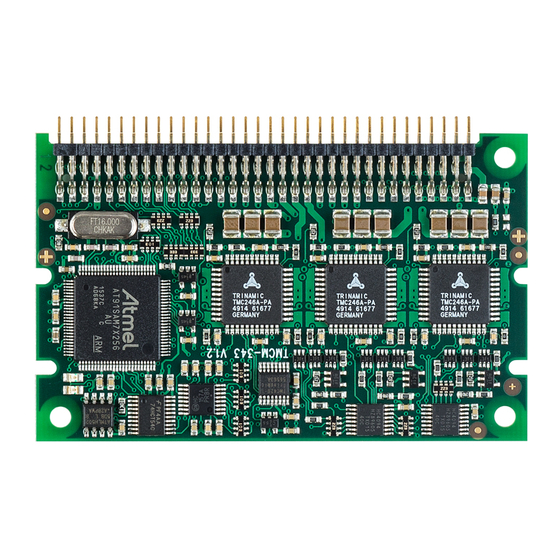
Trinamic TMCM-343 Manual (88 pages)
Brand:
Trinamic
| Category:
Control Unit
| Size: 1 MB
Table of Contents
Table of Contents
2
1 Life Support Policy
6
2 About this Document
7
3 Features
8
Features of TMCM-341
8
Features of the TMCM-342
9
Features of the TMCM-343
10
Features of the TMCM-351
11
General Features of this Canopen Implementation
12
4 Order Codes
13
5 Communication
14
Reference Model
14
NMT State Machine
15
Figure 5.1: Overview Canopen NMT State Machine
15
Figure 5.2: Communication Architecture
16
Device Model
17
Figure 5.3: Device Model
17
Object Dictionary
18
6 Communication Objects
19
Detailed Object Specifications
19
Object 1000
19
Object 1001 : Error Register
19
Object 1005 : COB-ID SYNC Message
20
Object 1008 : Manufacturer Device Name
20
Object 1009 : Manufacturer Hardware Version
20
Store Parameters
21
Object 1011 : Restore Default Parameters
22
Figure 6.1: Restore Procedure
22
Object 100A : Manufacturer Software Version
23
Object 1014 : COB-ID Emergency Object
23
Object 1015 : Inhibit Time EMCY
24
Object 1016 : Consumer Heartbeat Time
24
Producer Heartbeat Time
24
Object 1018 : Identity Object
25
Object 1023 : os Command
25
Object 1029 : Error Behavior
26
Objects 1400 : Receive PDO Communication Parameter
26
Objects 1440
27
Receive PDO Communication Parameter
27
Objects 1480
27
Objects 1600
28
Receive PDO Mapping
28
Objects 1800 : Transmit PDO Communication Parameter
31
Objects 1840
31
Transmit PDO Communication Parameter
32
Objects 1880
33
Transmit PDO Communication Parameter
33
Objects 1A00 -1A05 : Transmit PDO Mapping Parameter
34
Objects 1A40 : Transmit PDO Mapping Parameter
35
Objects 1A80 : Transmit PDO Mapping Parameter
36
7 Device Profile Objects (Cia402) and Modes of Operation
37
Detailed Object Specifications
37
Object 605A , and 705A : Quick Stop Option Code
37
685A
37
Object 605B , 685B , and 705B : Shutdown Option Code
38
Object 605C , 685C , and 705C : Disable Operation Option Code
38
Object 605D , 685D , and 705D : Halt Option Code
39
Object 605E , 685E , and 705E : Fault Reaction Option Code
39
Object 6060
40
H : Modes of Operation
40
Object 6061
40
H : Modes of Operation Display
40
Object 606A , 686A , and 706A : Sensor Selection Code
41
Object 60C5 , 68C5 , and 70C5 : Max Acceleration
41
Object 60C6 , 68C6 , and 70C6 : Max Deceleration
41
Object 60FD
42
68FD , and 70FD H : Digital Inputs
42
Object 6502 , 6D02 , and 7502 : Supported Drive Modes
42
Profile Position Mode
43
Detailed Object Specifications
43
Figure 7.1: Finite State Machine
43
Object 6040
44
And 7040 : Controlword
44
Object 6041
45
And 7041 H : Statusword
45
Object 6062
46
Object 6063
46
And 7063 : Position Actual Internal Value
46
Object 6064
46
And 7064 : Position Actual Value
46
Object 6065
47
And 7065 : Following Error Window
47
Object 6067 , and 7067 : Position Window
47
Object 6068
48
And 7068 : Position Window Time
48
Object 607A , and 707A : Target Position
48
687A
48
Object 607D , 687D , and 707D : Software Position Limit
49
Object 607F , 687F , and 707F : Maximum Profile Velocity
49
Object 6081 , and 7081 : Profile Velocity
50
Object 6083 , and 7083 : Profile Acceleration
50
Object 6084 , and 7084 : Profile Deceleration
50
Object 6085
51
And 7085 : Quick Stop Deceleration
51
Object 6086
51
And 7086 : Motion Profile Type
51
Object 608F , 688F , and 708F : Position Encoder Resolution
52
How to Move a Motor in Pp Mode
52
Homing Mode
53
Figure 7.2: Homing Mode Function
53
Connecting Home Switch, Left Switch, and Right Switch
54
Tmcm-341/342/343
54
Figure 7.3: 68-Pin Connector of the TMCM-34X
54
Figure 7.4: Pin Order of the Connector
54
Tmcm-351
55
Figure 7.5: Connectors of TMCM-351
55
Connecting a Brake
56
Tmcm-341/342/343
56
Tmcm-351
56
Figure 7.6: Homing on Negative Home Switch and Index Pulse
57
Homing Methods: Homing on Negative Home Switch and Index Pulse
57
Detailed Object Definitions
58
Object 6040 , and 7040 : Controlword
58
Object 6041 , 6841 , and 7041 : Statusword
59
Object 607C , 687C , and 707C : Home Offset
60
Object 6098 , and 7098 : Homing Method
60
Figure 7.7: Home Offset Definition
60
Object 6099 , and 7099 : Homing Speeds
61
Object 609A , 689A , and 709A : Homing Acceleration
61
How to Start a Homing in Hm Mode
61
Velocity Mode
62
Detailed Object Definitions
62
Object 6040
62
And 7040 : Controlword
62
Object 6041
63
And 7041 : Statusword
63
Object 6042 , and 7042 : Vl Target Velocity
63
Object 6043
64
And 7043 : Vl Velocity Demand
64
Object 6044
64
And 7044 : Vl Velocity Actual Value
64
Object 6046
64
And 7046 : Vl Velocity Min Max Amount
64
Object 6048
65
And 7048 : Vl Velocity Acceleration
65
Object 6049 , and 7049 : Vl Velocity Deceleration
65
Figure 7.8: Transfer Characteristic of the Velocity Acceleration
65
Object 6062 , Demand 7062 : Position Demdemand Value
66
Object 6063
66
And 7063 : Position Actual Internal Value
66
Object 6064
66
And 7064 : Position Actual Value
66
Object 6065
67
And 7065 : Following Error Window
67
Object 607D , 687D , and 707D : Software Position Limit
67
Object 6083 , and 7083 : Profile Acceleration
68
Object 6084 , and 7084 : Profile Deceleration
68
Object 6085
69
And 7085 : Quick Stop Deceleration
69
How to Move a Motor in Vl Mode
69
8 Manufacturer Specific Area
70
Detailed Object Specifications
70
Object 2000
70
Microstep Resolution
70
Object 2001
70
Fullstep Resolution
70
Object 2002
71
And 2402 : Brake Delay Times
71
Object 2003
71
H : Maximum Current
71
Figure 8.1: Brake Output Timing
71
Object 2004
72
2204 : Standby Current
72
Object 2005
72
Limit Switches
72
Object 2006
73
And 2406 : Mixed Decay Threshold
73
Object 2007
73
And 2407 : Stall Detection Threshold
73
Object 2009
73
Fullstep Threshold
73
Object 200A , and 240A : Enable Drive Delay Time
74
220A
74
Object 200B , 220B , and 240B : Encoder Parameters
74
Object 200C , 220C , and 240C : Brake Current Feed
75
Object 2085 , 2285 , and 2485 : Ramp Divisor
75
Object 2086 , and 2486 : Pulse Divisor
76
Object 2087 , and 2487 : Maximum Velocity
76
Object 2088 , 2288 , and 2488 : Maximum Acceleration
77
Object 208C , 228C , and 248C : Velocity Dimension Index
77
Object 208E , 228E , and 248E : Acceleration Dimension Index
77
Object 2100
78
And 2500 : Home Offset Display
78
Object 2101 , and 2501 : Actual Stallguard™ Load Value
78
Object 2102
78
And 2502 : Driver Error Flags
78
Object 2103
79
And 2503 : Pulse Divisor Display
79
Object 2104
79
And 2504 : Maximum Velocity Display
79
Object 2105
79
And 2505 : Ramp Divisor Display
79
Object 2106 , 2306 , and 2506 : Maximum Acceleration Display
80
Object 2107
80
And 2507 : Microstep Resolution Display
80
Object 2700 : TMCL™ Direct Communication
80
Object 2701 : Manufacturer Specific Mode
81
Object 2702 : Digital Inputs
81
Object 2703 : Digital Outputs
81
Object 2704 : CAN Bit Rate
82
Object 2705 : Node ID
82
Object 2706 : Store
82
Object 2707 : CAN Bit Rate Load
83
Object 2708 : Node ID Load
83
Object 2709 : Encoder Interface
83
Object 270A : Encoder Interface Display
83
Object 270E : Analog Inputs
83
9 Emergency Messages
85
10 Revision History
87
Firmware Revision
87
Document Revision
87
11 References
88
Advertisement
Trinamic TMCM-343 Manual (89 pages)
Brand:
Trinamic
| Category:
Control Unit
| Size: 2 MB
Table of Contents
Table of Contents
2
Preface
6
General Features of the Canopen Implementation
6
Abbreviations
7
Firmware Update
7
Communication
8
Reference Model
8
NMT State Machine
9
Figure 2.1 Overview Canopen NMT State Machine
9
Figure 2.2 Communication Architecture
10
Device Model
11
Figure 2.3 Device Model
11
Object Dictionary
12
Communication Objects
13
Detailed Object Specifications
13
Object 1000
13
H : Device Type
13
Object 1001 : Error Register
13
Object 1005 : COB-ID SYNC Message
14
Object 1008 : Manufacturer Device Name
14
Object 1009 : Manufacturer Hardware Version
14
Object 100A H : Manufacturer Software Version
14
Object 100C
15
Guard Time
15
Object 100D : Life Time Factor
15
Object 1011 : Restore Default Parameters
16
Figure 3.1 Restore Procedure
17
Object 1014 : COB-ID Emergency Object
18
Object 1015 : Inhibit Time EMCY
18
Object 1016 : Consumer Heartbeat Time
18
Object 1017 : Producer Heartbeat Time
18
Object 1018 : Identity Object
19
Object 1023 : os Command
19
Object 1029 : Error Behavior
19
Objects 1400 : Receive PDO Communication Parameter
20
Objects 1440 : Receive PDO Communication Parameter
20
Objects 1480
21
Objects 1600
22
H : Receive PDO Mapping
22
Objects 1800 -1805 : Transmit PDO Communication Parameter
25
Objects 1840
26
Objects 1880
27
Objects 1A00 H -1A05 H : Transmit PDO Mapping Parameter
28
Objects 1A40
29
Objects 1A80 -1A85 : Transmit PDO Mapping Parameter
30
Device Profile Objects (Cia402) and Modes of Operation
31
Detailed Object Specifications
31
Object 605A H , 685A H , and 705A H : Quick Stop Option Code
31
Object 605D , 685D : Halt Option Code
32
Object 605E
33
H : Fault Reaction Option Code
33
Object 608F
33
Object 60C5
33
Object 60C6
36
Object 60FD , 68FD , and 70FD : Digital Inputs
36
Object 6502 , and 7502 : Supported Drive Modes
37
Profile Position Mode
38
Detailed Object Specifications
38
Figure 4.1 Finite State Machine
38
Object 6040 , and 7040 : Controlword
39
Object 6041
40
And 7041 H : Statusword
40
Object 6067 , 6867 : Position Window
42
Object 6068 , and 7068 : Position Window Time
43
Object 607A , 687A , and 707A : Target Position
43
Object 607D , 687D , and 707D : Software Position Limit
44
Object 6081 , and 7081 : Profile Velocity
44
Object 6083 , 6883 : Profile Acceleration
45
How to Move a Motor in Pp Mode
46
Homing Mode
47
Figure 4.2 Homing Mode Function (Motor 0)
47
Connecting Home Switch, Left Switch, and Right Switch
48
Tmcm-341/342/343
48
Figure 4.3: 68-Pin Connector of the TMCM-34X
48
Figure 4.4: Pin Order of the Connector
48
Tmcm-351
49
Figure 4.5: Connectors of TMCM-351
49
Connecting a Brake
50
Tmcm-341/342/343
50
Tmcm-351
50
Homing Methods
51
Figure 4.6 Homing on Negative Switch and Index Pulse
51
Figure 4.7 Homing on Positive Limit Switch and Index Pulse
51
Figure 4.8 Homing on Positive Home Switch and Index Pulse
52
Figure 4.9 Homing on Negative Home Switch and Index Pulse
52
Figure 4.10 Homing Without Index Pulse
53
Figure 4.11 Homing on Index Pulse
53
Detailed Object Definitions
54
Object 607C , and 707C : Home Offset
56
Object 6098 , and 7098 : Homing Method
56
Figure 4.12 Home Offset Definition
56
Object 2100 : Home Offset Display
57
How to Start a Homing in Hm Mode
58
Velocity Mode
59
Detailed Object Definitions
59
Object 6043
61
And 7043 H : Vl Velocity Demand
61
Object 6044
61
And 7044 H : Vl Velocity Actual Value
61
Figure 4.13 Transfer Characteristic of the Velocity Acceleration
62
How to Move a Motor in Vl Mode
63
Profile Velocity Mode
64
Object 6040 , and 7040 : Controlword
64
Object 6063
66
And 7063 H : Position Actual Internal Value
66
Object 6064
66
And 7064 H : Position Actual Value
66
Object 606C H , 686C H , and 706C H : Velocity Actual Value
67
Object 607D , and 707D : Software Position Limit
67
Object 6083 , and 7083 : Profile Acceleration
67
How to Move a Motor in Pv Mode
68
Manufacturer Specific Area
69
Detailed Object Specifications
69
Object 2000 , and 2400 : Microstep Resolution
69
Object 2001 , and 2401 : Fullstep Resolution
69
Object 2003 , 2203 : Maximum Current
70
And 2403
70
Figure 5.1 Brake Output Timing
70
Object 2004 , 2204 : Standby Current
71
And 2404
71
Object 200A
73
H : Enable Drive Delay Time
73
Object 200B , 220B : Encoder Parameters
73
Object 200C
74
Object 204Eh, 224Eh, and 244Eh: Boost Current
74
Object 2085
74
Object 2086 , 2286 , and 2486 : Pulse Divisor
75
Object 2087 , 2287 , and 2487 : Maximum Velocity
75
Object 2088 , 2288 : Maximum Acceleration
76
And 2488
76
Object 208C , 228C , and 248C : Velocity Dimension Index
76
Object 208E
77
Object 2100
77
Object 2101
77
And 2501 H : Actual Stallguard™ Load Value
77
Object 2102 , 2302 : Driver Error Flags
78
And 2502
78
Object 2103
78
Object 2104
78
Object 2105
79
Object 2106 , 2306 : Maximum Acceleration Display
79
Object 2107 , 2307 : Microstep Resolution Display
79
And 2507
79
Object 2700 : TMCL™ Direct Communication
79
Object 2701 : Manufacturer Specific Mode
80
Object 2702 : Digital Inputs
80
Object 2703 : Digital Outputs
80
Object 2704 : CAN Bit Rate
81
Object 2705 : Node ID
81
Object 2706 : Store
82
Object 2707 : CAN Bit Rate Load
82
Object 2708 : Node ID Load
82
Object 2709 : Encoder Interface
82
Object 270A : Encoder Interface Display
83
Object 270E : Device Analog Inputs
83
Object 2710 : Pull-Up Resistors (TMCM-351 Only)
83
Emergency Messages
84
Life Support Policy
86
Revision History
87
Firmware Revision
87
Document Revision
88
References
89
Trinamic TMCM-343 Hardware Manual (27 pages)
CANopen firmware
Brand:
Trinamic
| Category:
Controller
| Size: 0 MB
Table of Contents
Table of Contents
2
1 Life Support Policy
4
2 Features
5
4 Order Codes
6
5 Electrical and Mechanical Interfacing
7
Dimensions
7
Connecting the Module
8
Power Supply Requirements
9
6 Operational Ratings
11
7 Functional Description
12
System Architecture
12
Microcontroller
12
Eeprom
12
TMC428 Motion Controller
13
Stepper Motor Drivers
13
Power Supply
13
Motor Connection
13
Host Communication
14
CAN 2.0B
14
Rs232
15
Rs485
15
Stallguard™ - Sensorless Motor Stall Detection
16
Stallguard™ Adjusting Tool
16
Stallguard™ Profiler
17
Reference Switches
18
Left and Right Limit Switches
18
Triple Switch Configuration
18
One Limit Switch for Circular Systems
19
Serial Peripheral Interface (SPI)
19
Additional Inputs and Outputs
19
Miscellaneous Connections
19
Microstep Resolution
20
8 Putting the TMCM-343 into Operation
21
9 Migrating from the TMCM-303 to the TMCM-343
22
10 TMCM-343 Operational Description
23
Calculation: Velocity and Acceleration Vs. Microstep and Fullstep Frequency
23
11 Tmcl
25
12 Canopen
25
13 Revision History
26
Document Revision
26
Hardware Revision
26
Firmware Revision
26
14 References
27
Advertisement
Advertisement
Related Products
Trinamic TMCM-3230
Trinamic TMCM-3351
Trinamic TMCM-3314
Trinamic TMCM-341
Trinamic TMCM-1021 TMCL
Trinamic TMCM-1076
Trinamic TMCM-1240
Trinamic TMCM-6214
Trinamic PANdrive TMCM-013
Trinamic PANdrive TMCM-013-LA
Trinamic Categories
Controller
Control Unit
Motherboard
Computer Hardware
Engine
More Trinamic Manuals
Login
Sign In
OR
Sign in with Facebook
Sign in with Google
Upload manual
Upload from disk
Upload from URL