Advertisement
Quick Links
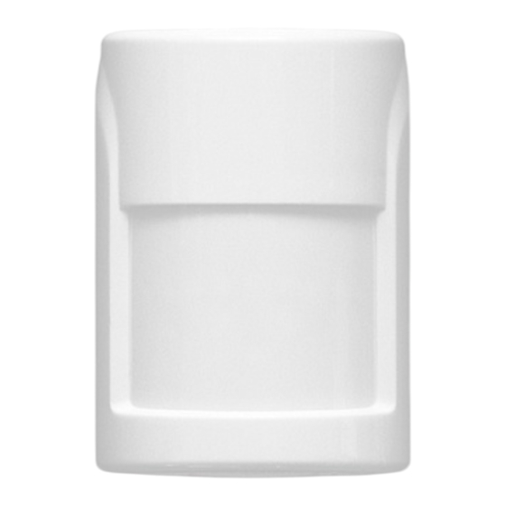
The present Operating Manual is intended to provide a guid-
ance on operating principles, correct use, storage and mainte-
nance for the PIR detector "Astra-517" (hereinafter-detector)
(Figure1).
The manufacturer reserves the right to make improvements in
the design of the detector without prior notice. The alternations
shall be included into a new edition of the Operating Manual.
1 Application
1.1 The detector is purposed to detect in-
trusion into a protected area indoors and to
generate an alarm notification by opening
of the signal relay output contacts.
1.2 The detector is powered from any DC
power supply with nominal voltage of
12V and maximum pulsation amplitude
0,1V.
2 Principle of Operation
2.1 The operating principle
is based on registration of
changes occurring in ther-
mal flux, when a person
crosses a detection zone,
consisting
of
sensitive
zones. Each sensitive zone
consists of two elementary
sensitive zones (Figure 2).
The sensitive zones of the
detector are formed by a
Fresnel lens and a bi-areal
pyroelectric sensor.
Electric signals from the
pyroelectric sensor shall be
sent to a microcontroller,
which generates alarm no-
tification
in
accordance
with a preset operation al-
gorithm by opening of op-
toelectronic relay circuit.
2.2 The sizes of detection
zone may be varied due to
the position of the printed circuit board of the detector. With in-
trusion detection range of 8 m, density of the sensitive areas
will be increased.
3 Specifications
Technical Parameters of PIR-channel
Intrusion detection range, m, min:
- lower PC board position ............................................................... 12
- upper PC board position ................................................................ 8
Sizes of detection zone at viewing angle 90
plane, m:
- in lower PC board position ................................................. 12×12
- in upper PC board position ......................................................... 8×8
Detectable motion speed range, m/s ................. from 0.3 to 3.0
Resistance to ambient light, lx, min ................................... 6500
Advised mounting height, m ................................ from 2.2 to 2.4
General technical parameters
Power supply voltage, V .......................................... from 8 to 15
Current consumption in standby
mode and in Alarm mode, mA, max ....................................... 12
Permissible current through relay contacts, А, max............. 0,08
Permissible voltage on relay contacts, V, max ..................... 100
Resistance of circuit connected to
Редакция 517-v1_0
Astra-517 (Volumetric Lens)
Optic-Electronic PIR Motion Detector
Operating Manual
Figure 1
Figure 1
о
in horizontal
alarm loop in standby mode, Ohm, max
Dimensions, mm, max ............................................... 70×51×41
Weight, kg max ................................................................... 0,05
Operating Conditions
Temperature range, °С .................................... from - 30 to + 50
Relative air humidity, % .................................... up to 98 at + 25 °С
4 Delivery Set
PIR motion detector Astra-517 ........................................... 1 pcs.
Bracket ............................................................................... 1 pcs.
Screw 2,9х25 (or 2-3х30) ................................................... 2 pcs.
Dowel 5х25 ........................................................................ 2 pcs.
User instruction .................................................................. 1 pcs.
5 Structure
5.1 The detector is a unit consisting of a base and a detacha-
ble cover. A printed circuit board with radio elements and a
block of screw terminals for external connections is installed
inside the unit. (Figure 3).
5.2 The PC board shall be secured in the position to enable the
desired detection range (8m, 12m) of the detector with a
screw.
5.3 The PC board includes an indicator, which controls operation
of the detector.
5.4 The cover on the inside is provided with a lock pin holding
down and securing the lens.
5.5 The pyroelectric sensor is equipped with a cap provided
with a reflector making a near detection area.
WARNING!
It is prohibited to operate the detector without the
cap.
5.6 The detector can be mounted either directly on the wall or
in a room corner, or it can be mounted using brackets (includ-
ed in the scope of delivery).
.
................................ 8
without moisture condensation
Figure 3
Advertisement

Subscribe to Our Youtube Channel
Related Manuals for teko Astra-517


Summary of Contents for teko Astra-517
- Page 1 Ohm, max ........ 8 ance on operating principles, correct use, storage and mainte- Dimensions, mm, max ..........70×51×41 nance for the PIR detector “Astra-517” (hereinafter-detector) Weight, kg max ..............0,05 (Figure1). Operating Conditions The manufacturer reserves the right to make improvements in Temperature range, °С...
- Page 2 erating ones, the detector must be left unpacked in operating 6 Information Capacity environment for minimum 4 hours. Table 1 - Notifications to indicator and relay 8.3 How to select mounting location Event Type Indicator Relay 8.3.1 Recommended mounting height After power is on, blinks Switching to once per second within...
- Page 3 3а WALL MOUNTING CORNER MOUNTING Match nib on the base hook with a slot on the PC board depending on the chosen de- tection range. Secure the PC board with a screw. Connect wires to the detector terminals MOUNTING USING BRACKET Press out blanks from brack- et mounting slots Switch the detector ON.
- Page 4 - conformance mark (if there is any certificate of conformance); Sales, technical support: - barcode, which backups the text information. ТЕКО-TD, LLC Prospekt Pobedy str. 19 420138 Kazan, Russia Phone: +7 (843) 261-55-75 Fax: +7 (843) 261-58-08 E-mail: info@teko.biz support@teko.biz Web: www.teko.biz Made in Russia Редакция 517-v1_0...
Need help?
Do you have a question about the Astra-517 and is the answer not in the manual?
Questions and answers