Advertisement
Quick Links
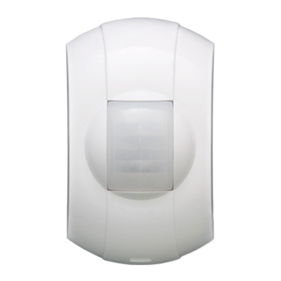
The present operation manual is intended for studying operation
principle, running conditions and maintenance of PIR motion de-
tector Astra-531 ver.PIR (hereinafter "detector") (Figure 1).
The manufacturer reserves the right to make alteration regarding
refinement of the product without prior notification. All changes
will be imported into new edition of the operation manual.
1
Function
1.1
Detector
is
intended
unauthorized
access
protected area, and to generate an alarm
notification by opening alarm relay contacts.
1.2
Power supply of detector is performed
from any direct current source with nominal
voltage 12V and pulsation amplitude not
exceeding 0,1V.
2
Principle of Operation
Detector operation principle is based on registration of thermal
background change of the room occurring on crossing sensitive
zones by a man. Detector sensitive zones are formed by Fresnel
lens and bi-areal pyroelectric radiation receiver. Pyroelectric re-
ceiver sends electric signal to microcontroller, which in its turn
generates an "Alarm" notification by opening of output circuit of
optoelectronic relay in accordance with pre-set algorithm.
Side view
5 m
0
5m
5 m
3
Specifications
Technical Parameters of Optical Channel
Maximal detection range, m ......................................................... 5
Viewing angle in horizontal plane, deg., not exceeding .............. 30
Viewing angle in vertical plane, deg., not exceeding .................. 95
General Technical Parameters
Power supply voltage, V ......................................... from 8 up to 15
Current consumption in „Alarm‟ and Stand-by mode, mA, not ex-
ceeding ....................................................................................... 18
Technical readiness time, s, not exceeding ................................... 60
Stand-alone mode start duration, s, not exceeding ........................ 10
Permissible current of signaling relay circuit, A, not exceeding .... 0.08
Permissible voltage on relay contacts, V, not exceeding .......... 100
Relay circuit resistance in Stand-by mode, Ohm ...... from 6 up to 8
TMP circuit permissible current, A, max .................................. 0.05
TMP circuit permissible voltage, V, max ..................................... 72
Overall dimension, mm, not exceeding........................... 62х37х27
Detector weight, kg, not exceeding ......................................... 0.03
Astra-531 Ver.PIR (Surface Lens)
Optic-Electronic PIR Motion Detector
to
detect
into
an
enclosed
Figure 1
Top view
Figure 2
Operation Manual
Running Conditions:
Temperature range, °C ................................... from - 20 up to + 50
Relative air humidity, % ..................................... up to 95 at +35 °С
4
Delivery Set
PIR motion detector Astra-531 ver.PIR .................................. 1 pcs
Bracket .................................................................................. 1 pcs
Screw 2,9х25 (or 2-3х30) ...................................................... 2 pcs
Dowel 5x25 ............................................................................ 2 pcs
Jumper ................................................................................... 2 pcs
User Instruction .................................................................... 1 copy
5
Structure
Structurally, the detector is designed as a unit, consisting of a
base and a removable cover. Installed inside the unit is a printed
circuit board with radio elements and screw terminals block for
external wire connections (see figure 3).
PIR plug
Mem plug
LED
2.5 m
Wire entry hole
5 m
without moisture condensation
Cover removed
Tamper switch
Mounting
holes
PIR sensor
Screw
terminals
Base
Figure 3
Advertisement

Related Manuals for teko Astra-531 Ver.PIR


Summary of Contents for teko Astra-531 Ver.PIR
- Page 1 All changes will be imported into new edition of the operation manual. Delivery Set Function PIR motion detector Astra-531 ver.PIR ........1 pcs Bracket .................. 1 pcs Detector intended detect Screw 2,9х25 (or 2-3х30) ............
- Page 2 Information Capacity Installation Procedure Works on installation, mounting, maintenance and operation Table 1 - Events and notifications to LED and relay of detector should be performed by only qualified persons. Event type Relay After transportation in conditions differing from those of oper- ation keep detector unpacked under supposed operation condi- Flashes 1 time per 1s after tions for at least 4 hours.
- Page 3 8.4 Installation procedure Step-7a Step-7b Lead wires from power Align the tabs of the base with Step-1 Step-2 Push out cover lock Unbend hooks supply source and signal- the bracket ball slot and partially ing zones through wire screw the screw from the inside from base slot.
- Page 4 Phone: +49 (0) 203 / 393 91 188 Phone: +7 (843) 261-55-75 Fax: +49 (0) 203 / 393 91 189 Fax: +7 (843) 261-58-08 GSM: +49 (0) 178 / 218 48 22 E-mail: info@teko.biz E-mail: info@controlex.eu support@teko.biz Web: www.controlex.eu Web: www.teko.biz...
Need help?
Do you have a question about the Astra-531 Ver.PIR and is the answer not in the manual?
Questions and answers