Table of Contents
Advertisement
Quick Links
NAV E 101 DTP • Setup Guide
This guide provides instructions for an experienced installer to install the Extron NAV E 101 DTP
streaming encoder and to make all connections. The Extron NAV encoder and one or more
compatible decoders form an AV distribution and switching matrix on a managed 1G IP network.
For more information on any subject in this guide, see the NAV E 101 DTP User Guide, available at www.extron.com.
NOTE:
Installation
Step 1 — Mounting
Turn off or disconnect all equipment power sources and mount the NAV E 101 DTP as required.
Step 2 — Rear Panel Connections
0.8A MAX
100-240V
50-60Hz
E
E E
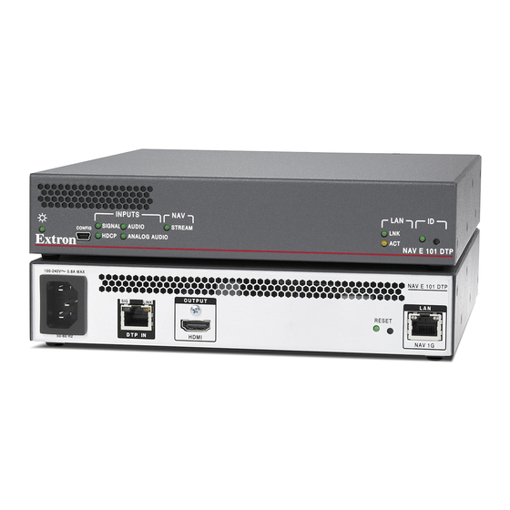
NAV E 101 DTP Rear Panel Features
Figure 1.
A
DTP input port — Plug a compatible Extron DTP signal into this RJ-45 port using a TP cable. See
the connectors.
ATTENTION:
•
Do not connect this port to a computer data or telecommunications network.
•
Ne connectez pas ces port à des données informatiques ou à un réseau de télécommunications.
NOTE:
The encoder can supply power to the connected DTP transmitter, such as a DTP 330 Tx, via power over DTP.
B
HDMI Output port — Connect a display to this female HDMI connector for local loop-through monitoring of the source signal. See
LockIt® Lacing Bracket
C
NAV 1G port — Connect to an Ethernet LAN on which one or more decoders also reside for streaming and control.
D
Reset button — This button initiates three modes of reset. See the NAV E 101 DTP User Guide, available at www.extron.com, for
details.
E
Power connector — Plug the encoder into a grounded AC source.
OUTPUT
SIG
LINK
DTP IN
HDMI
A
A A
B
B B
on page 5 to securely fasten the HDMI connectors to the encoder.
NAV E 101 DTP
LAN
RESET
NAV 1G
D
D D
C
C C
on page 5 to wire
1
Advertisement
Table of Contents

Related Manuals for Extron electronics NAV E 101 DTP


Summary of Contents for Extron electronics NAV E 101 DTP
- Page 1 NAV 1G port — Connect to an Ethernet LAN on which one or more decoders also reside for streaming and control. Reset button — This button initiates three modes of reset. See the NAV E 101 DTP User Guide, available at www.extron.com, for details.
- Page 2 The port uses IP over USB technology; the IP address is always 203.0.113.22 and CANNOT be changed. The Config port is also discoverable via Toolbelt (see the NAV E 101 DTP User Guide; the guide and Toolbelt are available for download at www.extron.com).
- Page 3 The “Connection via web pages,” Connection settings (see page 4), and Pairing devices via front panel procedures (see NOTE: page 5) may NOT be necessary if your system includes a NAVigator System Manager. Connection via web pages Connection to the encoder and its embedded web pages can be made via either the front panel Configuration (USB) port (using IP over USB technology) (see figure 2, on page 2) or the rear panel NAV 1G port (see figure 1, on page 1).
- Page 4 1 1 1 1 1 1 1 1 1 1 1 1 Home Page Figure 5. Detailed descriptions of communication, configuration, and monitoring are provided in the NAV E 101 DTP User Guide, NOTE: available at www.extron.com. Connection settings View and change connection settings as follows:...
- Page 5 Pairing devices via front panel Pair devices from the front panel as follows: Use a Tweeker or other small screwdriver to press and hold the encoder front panel ID button for approximately 3 seconds, until the ID LED blinks. The encoder enters pairing mode, which allows decoders to receive AV streams from encoders.
- Page 6 NAV E 101 DTP • Setup Guide (Continued) For information on safety guidelines, regulatory compliances, EMI/EMF compatibility, accessibility, and related topics, see the Extron Safety and Regulatory Compliance Guide on the Extron website. www.extron.com served. © 2020 Extron Electronics — All rights re All trademarks mentioned are the property of their respective owners.
Need help?
Do you have a question about the NAV E 101 DTP and is the answer not in the manual?
Questions and answers