Advertisement
Quick Links
NAV 10E 501 and NAV 10E 101 • Setup Guide
CLASS 1 LASER PRODUCT, see
WARNING:
The NAV 10E 501 and NAV 10E 101 output continuous invisible light (Class 1 rated), which may be harmful to the
eyes; use with caution.
•
Do not look into the fiber optic cable connectors or into the fiber optic cables themselves.
•
Plug the attached dust caps into the optical transceivers when the fiber cable is unplugged.
AVERTISSEMENT :
être dangereuse pour les yeux ; à utiliser avec précaution.
•
Ne pas fixer directement les connecteurs optiques ou les câbles fibre optique.
•
Associez les bouchons anti-poussière à l'ensemble émetteur/récepteur optique lorsque le câble fibre optique est débranché.
This guide provides instructions for an experienced installer to install the Extron NAV 10E 501 and NAV 10E 101 streaming encoders and
to make all connections. The Extron NAV encoder and one or more compatible decoders form an AV distribution and switching matrix on a
managed 10G IP network.
NOTE
For more information on any subject in this guide, see the NAV 10E 501 and NAV 10E 101 User Guide, available at
:
.
www.extron.com
Installation
Step 1 — Mounting
Turn off or disconnect all equipment power sources and rack or furniture mount the encoder as required.
Step 2 — Rear Panel Connections
INPUT
POWER
12V
2.0 A MAX
HDMI
J J
J
A
A A
INPUT
POWER
12V
2.0 A MAX
HDMI
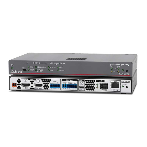
NAV 10E 501 and NAV 10E 101 Rear Panel Features
Figure 1.
A
HDMI input port — Connect an HDMI cable between this port and the HDMI output port (or DVI port, with an appropriate adapter) of
the digital video source.
B
HDMI Loop Thru port — Connect a display to this female HDMI connector for local loop-through monitoring of the source signal.
NOTE: See
LockIt
C
Audio input port — Connect balanced or unbalanced stereo audio input to this 5-pole, 3.5 mm captive screw connector (see
audio input
on page 6 to wire the connector).
D
Control Contact Closure port — Connect an Extron Show Me
the decoder, using the control system.
E
Control RS-232/IR port — Connect a serial RS-232 signal, a modulated IR signal, or both to this 3.5 mm, 5-pole captive screw
connector for bidirectional RS-232 and unidirectional IR communication with connected remote controlled devices using an Extron
control system (see
NAV 10E 501 and NAV 10E 101
Le NAV 10E 501 et le NAV 10E 101 émettent une lumière invisible en continu (équipement de classe 1) qui peut
AUDIO
L
LOOP THRU
B B
B
C
C C
AUDIO
L
LOOP THRU
on page 6 to securely fasten the HDMI connectors to the encoder for
Lacing Brackets
®
Control connector
on page 6 to wire the connector).
User Guide at
CONTROL
USB 2.0
R
CONT
RS-232
IR
C T Tx Rx G S G
5V/200 mA
D
D D
E
E E
F
F F
CONTROL
R
CONT
RS-232
IR
C T Tx Rx G S G
cable to this port to allow the encoder to select itself as the input to
®
.
www.extron.com
LAN
NAV 10G
EXT
G
G G
H
H H
LAN
NAV 10G
NAV 10E 501
RESET
I
I I
NAV 10E 101
RESET
and
.
A
B
Analog
1
Advertisement

Related Manuals for Extron electronics NAV 10E 501


Summary of Contents for Extron electronics NAV 10E 501
- Page 1 Associez les bouchons anti-poussière à l’ensemble émetteur/récepteur optique lorsque le câble fibre optique est débranché. This guide provides instructions for an experienced installer to install the Extron NAV 10E 501 and NAV 10E 101 streaming encoders and to make all connections. The Extron NAV encoder and one or more compatible decoders form an AV distribution and switching matrix on a managed 10G IP network.
- Page 2 IP over USB technology; the IP address is always 203.0.113.22 and CANNOT be changed. The Config port is also discoverable via Toolbelt (see the NAV 10E 501 and NAV 10E 101 User Guide, the guide and Toolbelt are available for download at www.extron.com).
-
Page 3: System Operation
NOT operational until the boot process is complete (the Power LED is lit steadily) System Operation The encoder can be configured and controlled using embedded web pages or Extron Toolbelt (see the NAV 10E 501 and NAV 10E 101 User Guide available at www.extron.com... - Page 4 NOTES: * For the Config port, the address for IP over USB • Default settings: CANNOT be changed. Port DHCP IP address Subnet mask If the unit does not receive a DHCP address, Config (USB)* 203.0.113.22 a self-assigned Link Local Address, is assigned in the range 169.254.X.X.
-
Page 5: Connection Settings
* NAV 10E 501 only HTML Page Figure 5. NOTE: Detailed descriptions of communication, configuration, and monitoring are provided in the NAV 10E 501 and NAV 10E 101 User Guide, available at www.extron.com. Connection settings View and change connection settings as follows:... -
Page 6: Connection Details
Use a Tweeker or other small screwdriver to press and release the encoder front panel ID button. The encoder exits pairing mode. Repeat steps 1 through 4 to pair decoders to other encoders. After all devices are connected, powered on, and paired, the system is fully operational. Operation in a System with a NAVigator The Extron NAVigator is a system manager that easily configures and controls the NAV System.
Need help?
Do you have a question about the NAV 10E 501 and is the answer not in the manual?
Questions and answers