Extron electronics SMP 351 3G-SDI User Manual
Streaming media processor smp 300 series
Hide thumbs
Also See for SMP 351 3G-SDI:
- User manual (166 pages) ,
- User manual (178 pages) ,
- Application note (8 pages)

Subscribe to Our Youtube Channel
Related Manuals for Extron electronics SMP 351 3G-SDI


Summary of Contents for Extron electronics SMP 351 3G-SDI
- Page 1 User Guide Streaming AV Product SMP 300 Series Streaming Media Processor Preliminary 68-2238-01 Rev. E 06 17...
-
Page 2: Safety Instructions
Safety Instructions Safety Instructions • English Istruzioni di sicurezza • Italiano WARNING: This symbol, , when used on the product, is intended to AVVERTENZA: Il simbolo, , se usato sul prodotto, serve ad alert the user of the presence of uninsulated dangerous voltage within avvertire l’utente della presenza di tensione non isolata pericolosa the product’s enclosure that may present a risk of electric shock. - Page 3 ついては、 エクス トロンのウェブサイ ト より 『Extron Safety www.extron.com and Regulatory Compliance Guide』 (P/N 68-290-01) をご覧ください。 Copyright © 2017 Extron Electronics. All rights reserved. Trademarks All trademarks mentioned in this guide are the properties of their respective owners. The following registered trademarks( ®...
- Page 4 FCC Class A Notice This equipment has been tested and found to comply with the limits for a Class A digital device, pursuant to part 15 of the FCC rules. The Class A limits provide reasonable protection against harmful interference when the equipment is operated in a commercial environment.
- Page 5 Conventions Used in this Guide Notifications The following notifications are used in this guide: ATTENTION: • Risk of property damage. • Risque de dommages matériels. NOTE: A note draws attention to important information. TIP: A tip provides a suggestion to make working with the application easier. Software Commands Commands are written in the fonts shown here: ^AR Merge Scene,,0p1 scene 1,1 ^B 51 ^W^C.0...
-
Page 6: Table Of Contents
Contents Web-Based User Interface ....... 50 Introduction ..........1 Overview of the Web-Based User Interface ..50 About this Guide ..........1 Web Browser Requirements ......51 About the SMP 300 Series ........1 Turning Off Compatibility Mode ...... 51 Suggested PC Requirements ......3 Web-based User Interface Help Files .... - Page 7 FlexOS Applications ......... 94 Push and Pull Streaming ......138 Push Stream and Pull Stream Playback About the FlexOS App - Digital I/O URLs ............139 Configurator ............ 94 Streaming Capabilities and System Scalability ............140 Remote Communication and Control ..
-
Page 8: Introduction
About this Guide This guide contains installation, configuration, and operating information for the SMP 351, SMP 351 3G-SDI, SMP 352, and SMP 352 3G-SDI. In this guide: • “SMP 300 Series”, “SMP models”, or “the SMP” refer to the SMP 351, SMP 351 3G-SDI, SMP 352, SMP 352 3G-SDI models. - Page 9 Figure 1. Typical SMP 351 Application Figure 2. Typical SMP 352 Application SMP 300 Series • Introduction...
-
Page 10: Suggested Pc Requirements
Suggested PC Requirements The suggested PC requirements to access the default web pages of the SMP are listed below. • Hardware 2.0 GHz Dual-Core processor • • Operating Systems Microsoft Windows XP or higher • 10.6 or higher • ® ®... - Page 11 Licensed Third-party Software Used in the SMP 300 Series Package License Package License cjson luasocket dbus AFLv2.1 GPLv2 luastruct e2fsprogs GPLv2, libuuid BSD-3c, lvm2 GPLv2 LGPLv2.1 libssGPLv2, libuuid BSD-3c, libss and libet MIT-like with advertising clause ethtool GPLv2 GPLv2 expat GPLv2 fbdump GPLv2...
-
Page 12: General Product Overview
The SMP 300 Series can accept up to three HDMI inputs and one component or composite video input. The SMP 351 3G-SDI and SMP 352 3G-SDI are identical to the SMP 351 and SMP 352 except that they include the 3G/HD/SDI input (input 5). Both models accept digital audio embedded on HDMI signals or analog audio input via captive screw connectors. -
Page 13: File Storage
SMP 300 Series Inputs Outputs Channel HDMI/DVI Frame rate rear panel conversion 1: HDMI/DVI local output 2: HDMI/DVI HDMI Loop- Recording through (unprocessed) External Channel Deinter- lacing, drive Automatic Archive scaling, 3: Analog (front or Internal upload of encoding rasterizing, component rear port, storage... -
Page 14: Control Options
Control Options The SMP 300 Series can be controlled using the following: • Front panel menus and controls • Simple Instruction Set (SIS) commands sent over Ethernet via the LAN connection, over RS-232 via the rear panel Remote captive screw connector, or over USB via the front panel Config port. -
Page 15: Features
Encoding the content into up to three encoding streams (two encoding streams [archive • and confidence] in composite mode, 3 encoding stream [ChA archive, ChB Archive and Encoder Settings and Layout Presets Confidence] in dual channel mode. See page 74). • SMP 351 models encode the content and layout into two encoding streams, archive and confidence. - Page 16 High quality scaling with flexible two-window management (For composite mode • only) — Display one or two high resolution sources in various window arrangements, including picture-in-picture and picture-by-picture arrangements for optimal interpretation. • Record to internal and USB storage simultaneously (For composite mode only) —...
- Page 17 Define specific storage destinations for recorded data — Configure the SMP 300 • Series to save recordings to specific storage directories based on the user environment or application requirements. • Manage AV recordings using Extron Streaming Content Manager — SCM prepares recording packages that offer an enhanced playback experience from the Extron Media Player.
- Page 18 Auto-Image setup — When activated, the unit automatically analyzes the incoming • video signal and then automatically adjusts sizing, centering, and filtering to optimize image quality. This can save time and effort in fine tuning displayed images. • Recording layout presets simplify control (Composite mode only)— The SMP 300 Series provides 16 standard or customizable presets that specify the size and positioning of AV sources and metadata, simplifying management and selection of layouts from the front panel or an external control system.
- Page 19 System workflow alarms — Notify monitoring systems or support staff if disk space • is low, encrypted signals are detected, AV signal errors occur, or other error conditions exist. • Alarm reporting — Automate communication with monitoring systems or support staff using e-mail via Simple Mail Transfer Protocol.
-
Page 20: Installation
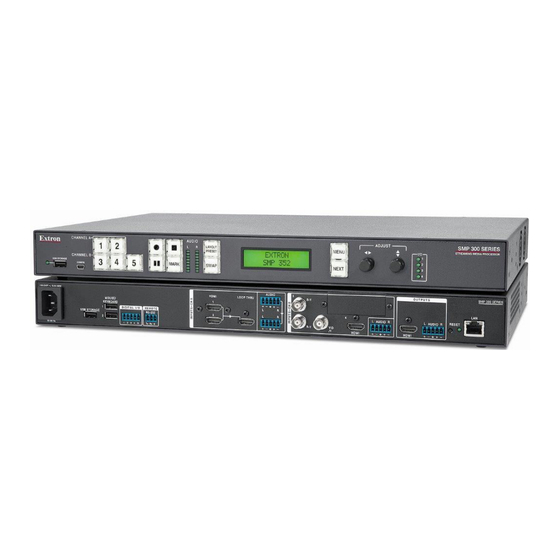
SMP 300 Series Rear Panel (SMP 351 3G-SDI shown) 100-240 VAC IEC connector for power input (Optional input 5) 3G/HD/SDI input card (SMP 351 3G-SDI and SMP 352 3G-SDI only) USB type A receptacle for external storage device 3.5 mm, 5-pole captive screw connector for channel B... -
Page 21: Power Connection
Power Connection 100-240 VAC power input – Connect the provided IEC cord. Verify the front panel buttons and LCD illuminate (see Front Panel Features on page 19). Control System and External Device Connections The SMP 300 Series can be configured and controlled from the Remote RS-232 port (see figure 4, on the previous page) or the front panel USB mini-B Config port (see figure... -
Page 22: Input Connections
HDMI input 4 – Connect an HDMI (or DVI with suitable adapter) source device to input 4. Serial digital video input 5 (SMP 351 3G-SDI and SMP 352 3G-SDI only) – Connect a 3G/HD/SDI video signal to this BNC connector. Channel B analog and 3G-SDI audio input – Connect a balanced or unbalanced stereo line level audio device to this 5-pole, 3.5 mm captive screw connector. - Page 23 ATTENTION: • The length of the exposed wires in the stripping process is important. The ideal length is 3/16 inch (5 mm). If longer, the exposed wires may touch, causing a short circuit between them. If shorter, the wires can be easily pulled out even if tightly fastened by the captive screws.
-
Page 24: Smp 300 Series Rear Panel Reset
SMP 300 Series Rear Panel Reset The Reset button on the rear panel of the SMP 300 Series (see figure 4 on page 13) returns the SMP 300 Series to various modes of operation. There are three unit reset modes (numbered 1, 4, and 5) that are initiated from the rear panel reset button. To select different reset modes, use a pointed stylus or small screwdriver to press and hold the Reset button while the SMP 300 Series is powered or press and hold the Reset button while applying power to the SMP 300 Series. - Page 25 SMP 300 Series Reset Modes Mode Activation Result Purpose and Notes Hold in the recessed rear The SMP 300 Series reverts to the Use mode 1 to revert to panel Reset button while factory default firmware for a single the factory default firmware applying power to the unit.
-
Page 26: Front Panel Operation
Front Panel Operation This section of the manual discusses the operation of the SMP 300 Series from the front panel. Topics covered include: • Front Panel Features Layout Presets (For Composite Mode Only) • • SMP 300 Series Power Up Procedure Front Panel Menu Operation •... - Page 27 Config port — Connect a control device to this port with a USB mini-B cable (not supplied). Use this port to send SIS commands to the SMP 300 Series for device configuration and control (see Remote Communication and Control starting on page 95).
-
Page 28: Layout Presets (For Composite Mode Only)
Menu display – Displays configuration menus and status information. Use the MENU and NEXT buttons ( ) and ADJUST knobs ( ) to navigate the menu. During normal operation, a default display cycle is presented (see SMP 300 Series Power Up Procedure on page 23). - Page 29 PBP Upper Left <1> PBP Mid Right <4> Side by Side <7> Fullscreen B <10> PbP 25%, main window 75% PbP 25%, main window 75% Windows horizontally centered main window 100% Ch. B 16:9 Ch. A Ch. B METADATA 16:9 16:9 Ch.
-
Page 30: Smp 300 Series Power Up Procedure
SMP 300 Series Power Up Procedure NOTE: Before powering the SMP 300 Series, ensure that all necessary devices are connected properly. Devices do not need to be powered. Connect the power cord to a 100 to 240 VAC supply (see Power Connection page 14). -
Page 31: Front Panel Menu Operation
Front Panel Menu Operation Configuration and adjustments can be performed B B C C E E F F using the embedded Web pages (see Overview of the Web-Based User Interface on page 50), Extron CHANNEL A SMP 30 AUDIO ADJUST L AYO U T M E N U PRESENTATION CA the SIS commands (see... -
Page 32: Presets Menu
Press the MENU button once to bring up the first main (top level) menu, as shown below. Each successive MENU button press cycles to the next main menu. NOTE: From any menu or submenu, after 30 seconds of inactivity, the SMP 300 Series times-out to the default display cycle. - Page 33 Menu Menu PRESETS PRESETS Next Next ARCHIVE ENCODER CHA ARCHIVE ENCODER RECALL <N/A> RECALL <N/A> Rotate horizontal knob to select Rotate either to encoder. Rotate vertical knob to select a preset to recall. select a preset to recall. Next Next ARCHIVE ENCODER CHA ARCHIVE ENCODER SAVE <N/A>...
- Page 34 Default encoder presets The first nine encoder presets are predefined. Preset 3 is the default value for the Archive Encoder (Channel A and Channel B). Preset 9 is the default value for the Confidence Encoder (Streaming = on by default). Preset Preset Resolution...
-
Page 35: Picture Control Menu
Each input has sixteen user preset locations available. A configuration can be saved to any preset number using this menu, the embedded Web pages, or via SIS. Select N/A and press NEXT to exit without saving settings. To recall a user preset from the front panel: Press MENU to cycle through the main menus to the Presets menu. - Page 36 NOTES: • * The position range depends on the selected resolution. • indicates applicable picture controls for the input type. • The position and size values are for archive encoding. Channel select This submenu selects the input channel for the remainder of the submenus. Rotate either ADJUST knob to select channel A and channel B.
- Page 37 To use this submenu: • Rotate the left ( ) ADJUST knob to adjust the color of the video for the selected input. When this configuration option is set to 0, colors appear as shades of gray. The range of settings is 000 to 127. The default is 064. •...
- Page 38 Record and Stream Configuration Menu This menu allows the user RECORD/STREAM Menu to configure the archive CONFIGURATION (recording) and confidence NEXT encodes. ENCODER ENCODER -OR- <CONFIDENCE> <ARCHIVE> Use either ADJUST knob Rotate either to Rotate either to select encoder type. select encoder type.
- Page 39 Recording mode RECORD/STREAM Menu CONFIGURATION NEXT ENCODER <ARCHIVE> Rotate either to select encoder type. NEXT ENCODER MODE ENCODER MODE <COMPOSITE> <DUAL> Rotate either to select Composite or Dual channel Mode. NEXT RECORDING RECORDING RECORDING <OFF> <Internal +2nd> <SINGLE> Rotate either to select Off, Single, or Secondary recording mode.
- Page 40 NOTE: When a USB device has more than one logical volume, each volume is numbered. Use the right ( ) ADJUST knob to select from among the different volumes on USB front, USB rear, and USB RCP storage devices. ATTENTION: •...
- Page 41 Record To (Internal + 2nd) The Record To submenu selects the drive the input records to. Selecting Dual assumes there is a USB drive connected. The input is always recorded to both the internal and external drives. Internal – Displays the available drive space for the internal drive. External –...
-
Page 42: Audio Output
Stream Protocol The available stream protocol follows push or pull streaming. When RTSP PULL streaming is selected, the user can choose between UNI RTP/UDP (default) and MULTI RTP/UDP. When RTP PUSH streaming is selected, the user can pick one of six options: UNI TS/UDP (default), UNI TS/RTP, UNI ES/RTP, MULTI TS/UDP, MULTI TS/RTP and MULTI ES/RTP. - Page 43 RECORD/STREAM MENU CONFIGURATION NEXT OUTPUT MODE <AUDIO/VIDEO> Rotate either to select audio and video, or video only. NEXT AUDIO OUTPUT AUDIO OUTPUT -OR- <B ONLY> <B DUAL MONO> Rotate either to Rotate either to select ChA, ChB or A+B. select B dual mono or A+B dual mono. NEXT NEXT Figure 22.
-
Page 44: Input Configuration Menu
Bit Rate (Video) Archive and confidence encodes have independent video bit rate settings. Video (VID) bit rate sets a target video bit rate from 200 kbps to 10000 kbps (default 5000 kbps). Rotate the left ( ) ADJUST knob to select the video bit rate. Bit Rate (Audio) Archive and confidence encodes have the same audio bit rate settings. -
Page 45: Aspect Ratio
NOTE: The Input Configuration submenus are input specific. Depending on the input type, not all submenus (shown in gray on subsequent pages) are available. Film detection (interlaced input formats only) INPUT MENU CONFIG Film detection is automatically enabled when an interlaced input format is selected (see NEXT Input format above). - Page 46 The aspect ratio can be changed per input. The selected input is displayed in the first line. Rotate either ADJUST knob to select FOLLOW, FILL (default), and FIT for the selected input. Aspect Ratio Screen Appearance Description The input format passes unchanged. A 4x3 format (represented by the red block on the left) remains at its original aspect ratio.
- Page 47 EDID Resolution Refresh Rate Rate Type Video Forma Audio 1280x1024 60 Hz 1360x768 60 Hz 1366x768 60 Hz 1400x1050 60 Hz 1440x900 60 Hz 1600x900 60 Hz 1600x1200 60 Hz 1680x1050 60 Hz NOTE: The Input Configuration submenus are input 1920x1080 60 Hz specific.
- Page 48 <FILL> Rotate either to select an aspect ratio for the selected input. EDID INPUT #[1] <720p_60_2ch> Rotate [ to set an EDID value for the ANALOG AUDIO — for analog audio from the rear panel captive screw connections • active input. (default) IN[1] AUDIO SELECT •...
- Page 49 The value is global to all analog inputs on the SMP 300 Series and defines the minimum luminosity that the Auto-Image routine defines as active video (default: 25%). Auto-Image affects active pixel, active lines, H/V start, and phase configurations. All other picture controls remain unchanged.
- Page 50 <1280X720@60Hz> Rotate either to select a resolution. Next AUTO MEMORY <ON> Rotate { to toggle Auto Memory On or Off. Test Patterns Next Test patterns are an essential tool for configuration and TEST PATTERN <N/A> troubleshooting. Rotate either to select a test pattern.
- Page 51 Reset Press and hold VIEW COMM The Reset submenu provides a factory reset or INPUT 5 + NEXT SETTINGS for 3 seconds. firmware reboot. The selections are: To Factory – Equivalent to a ZQQQ command “Hidden” Menu* (see Command and Response Tables starting on EDIT COMM SETTINGS...
-
Page 52: Comm Settings (View And Edit) Menu
Comm Settings (View and Edit) Menu XXX.XXX 192. The two Comm Settings menus provide a status of the XXX.XXX XXX. current serial port and IP settings for the communications ports. A hidden menu allows changes to the settings. Rotate [ to select octet. Rotate The main menu defaults to the VIEW COMM SETTINGS 192.XXX... -
Page 53: Status Menu
Status Menu The STATUS menu contains read-only EXIT MENU? submenus that show the current unit status MENU MENU STATUS PRESS NEXT including active alarms, recording file names, NEXT free space and total internal and external drive capacity, and bit rates for archive and ALARM STATUS [NONE, HDCP, VIDEO...] confidence streams. -
Page 54: Front Panel Lockout (Executive Modes)
Front Panel Lockout (Executive Modes) To prevent accidental changes to front panel menu settings, press MENU and MARK simultaneously for 3 seconds to enable front panel lockout mode. The menu system returns to the default menu within 10 seconds. Executive mode begins in mode 1. Rotate either ADJUST knob to cycle to mode 2, then mode 3, and mode 4 (Executive mode off). - Page 55 Alarm Alarm Generated Alarm Cleared • Audio Loss Alarm The SMP generates this alarm only during a During a recording, the audio signal is recording when either of the following conditions maintained above -60 dBFS for a contiguous are met: period of 60 seconds •...
- Page 56 Alarm Alarm Generated Alarm Cleared Schedule server The alarm is initiated when there is an error When the connection to the server is restored or communicating with the scheduling server. an alternate scheduling configuration is set. Firmware failure alarm The alarm is designed to indicate a failure to start a critical portion of the device’s operation.
-
Page 57: Web-Based User Interface
Ability to display alarm history and allow administrators to clear active alarms • • A way to update firmware • A way to upload and install a LinkLicense on an SMP 351 or SMP 351 3G-SDI SMP 300 Series • Web-Based User Interface... -
Page 58: Web Browser Requirements
Figure 25. SMP 300 Series Embedded Web Pages Web Browser Requirements In order to view the SMP 300 Series embedded web pages, use one of the supported Web browsers (and versions) listed below. • Google Chrome version 37 or higher NOTE: Chrome version 42 disables many plugins. For the SMP this means that the preview video in the AV Controls panel is not supported by Chrome version 42 or higher. -
Page 59: Web-Based User Interface Help Files
Web-based User Interface Help Files The SMP 300 Series Web-based User Interface contains an extensive set of help files to assist with the connection, configuration, monitoring, and operation of the SMP 300 Series. The following sections contain an overview of those files and also includes information not contained in the help files. -
Page 60: Pages Within Tabs
Recording Controls (see Recording Controls on page 61)— This single page provides a view of the status of currently selected inputs and outputs along with details of the active recording and stream (the current event) and a table-style list of upcoming scheduled events. - Page 61 Collapse and expand panes Click the Expand (see figure 29, ) arrow button on the right side of a pane. The pane opens to a full view, or as much as possible with the current display settings. Click the Collapse ( ) arrow button at the top corner of a pane to collapse it.
-
Page 62: Logging Out And Logging In
The idle status does not affect the recording or the output AV streams, which continue unaffected no matter what state (active or idle) the web pages are in. To reconnect the web page to the live feed from the SMP 300 Series, click Resume. In a moment, the browser refreshes the view, and the status updates and video confidence display resume. -
Page 63: Av Controls Panel
AV Controls Panel The AV Controls panel is available on every page and within all tab views. Located along the left side of the pages, this panel makes it possible to easily control a recording, see a thumbnail view of the recorded and output video, swap video content between windows, select different inputs, and mute or unmute the AV output. - Page 64 Recording controls Recording control buttons function the way controls do on a DVR or other recording device. Buttons include: • Record — Set up an ad hoc* recording session and start or resume recording. • Pause — Pause recording. Extend — Extend the duration of a recording event by ten minutes beyond the •...
-
Page 65: Start An Ad Hoc Recording
) — Composed of input 3 (component/composite), input 4 (HDMI), and • optional input 5 (3G/HD/SDI) for the SMP 351 3G-SDI and SMP 352 3G-SDI. There is one analog audio input per channel. HDMI inputs can be configured for digital audio (embedded in HDMI) or a shared analog input for the channel. - Page 66 NOTES: • Setting the Default Recording Media on page 82) within Configuration > System Settings for more information about single and dual storage modes. • If the unit is set for recording destination limiting, users do not have the option to select a different storage location.
- Page 67 Figure 34. Ad-Hoc Recording, Secondary Recording Destination Selection Select the secondary storage location from the drop-down list. If the unit is set to restricted mode, you can select only from front panel USB drives • or from rear panel USB drives, depending on whether the front or the rear option is selected in the system settings.
-
Page 68: Recording Controls
Recording Controls The Recording Controls page displays information about the active inputs and the output signal, the presentation event currently in progress, and a list of upcoming presentations. Information on this page updates every few seconds. Contents of the page are read-only and are displayed for all users. -
Page 69: Storage Information
Storage Information The storage information table below the Stream URL panel (also available in the File Management page) displays the names of the available connected storage devices, their locations (internal, USB front panel port, USB rear panel port, USB RCP port), total capacity, and amount of used and available storage space. -
Page 70: Scheduled Events
Scheduled Events The Scheduled Events tab includes three secondary tabs with corresponding pages that allow administrators to create scheduled recordings, publish (upload) them, and review the status of recordings. The three Scheduled Events pages are: Recording Calendar, Schedule Settings, and Publish Settings. Recording Calendar Page This page lists the currently selected scheduling source and publishing destination and when the schedule was last synchronized. - Page 71 Figure 37. Schedule Settings Page Read the SMP 300 Series Help File for details and step-by-step procedures on scheduling. A Note on Using the SMP 300 Series With an Opencast Server System The SMP supports HTTP ETags (entity tags), which make it possible to cache some scheduling information to minimize network traffic.
-
Page 72: Publish Settings Page
Publish Settings Page The Publish Settings page provides controls to specify the server destination to which completed recordings are uploaded and to configure and test protocols and settings to enable publication (uploading). This page also shares the Active Profiles panel with the Schedule Settings page. -
Page 73: Configuration
To select a publishing destination, select the desired radio button below the Active Publishing Destination for the following options: Active Publishing Destination Corresponding Tab Not Applicable No Centralized upload server. This is the default option. Extron SCM Extron SCM Ingest into Entwine EMP Entwine EMP Ingest into Kaltura Hosted Kaltura Ingest... -
Page 74: Configuration Tab Features
Configuration Tab Features figure 39 The pages within Configuration (see on page 66) include the following: Input/Output Settings — Provides a way to change the name for each input, select the video format for input 3, select an aspect ratio type, and enable or disable Auto-Image, Auto Memory, HDCP authorization for each input. -
Page 75: Input/Output Settings
Input/Output Settings The controls within the Input/Output Settings page within the Configuration tab allow an administrator to select a number of settings for video input, test the output, and select options for audio output format and mute. This page includes audio configuration controls for each channel (A and B). For the basic SMP 351 models, adjustments are for audio levels only. - Page 76 Changing the Font and Text Settings Used for the Input Switching On-screen Display If optional fonts are uploaded to the SMP 300 Series, you can select and use one for displaying OSD text instead of the default font. Size and color can be selected for the OSD text.
- Page 77 output. To select and output a test pattern: Open the Input/Output Settings page. Expand the OSD Configuration panel. Select a pattern from the Test Patterns drop-down list. A preview of the test pattern appears above the drop-down list. Available test patterns include the following: Color Bars Time Stamp Pulse...
- Page 78 down menus in the Universal OSD section become accessible. Enter the text (up to 16 characters) into the Display Text field within the universal OSD area. This is the first text that appears in the universal OSD, and can function as a brief title or description.
-
Page 79: Image Settings
figure 42 on page 72 on the next page has examples of how the configuration settings (on the left) translate to the universal OSD (on the right). REC1,CPU Usage 56% 00:10:33,20:10:51 OSD, SMP 351,1*4,up*100*full Figure 42. Universal OSD Information Selection Image Settings The controls within the Image Settings page within the Configuration tab provide a way to configure video input sampling and sizing, set up overscanning of SMPTE input signals, and adjust picture controls (brightness, contrast, and similar). - Page 80 SDI Settings – Set the quantization range for SDI signals from input 5 • (SMP 351 3G-SDI and 352 3G-SDI only). To open this page, click the Configuration tab at the top of the SMP Series embedded web pages and then click the Image Settings tab on the second tier of tabs. Figure 43.
-
Page 81: Encoder Settings And Layout Presets
Selecting SDI-specific Settings For input 5 of an SMP 351 3G-SDI and SMP 352 3G-SDI you can select the quantization range, which sets the black and white level for the RGB data of the SDI input. To set the quantization: Select one of the following options from the Quantization Range drop-down list: Legal —... - Page 82 Encoding Presets Encoding presets are combinations of settings for audio and video encoding. The recording uses the highest quality signal encoding (archive encoding) and the preview (confidence view) displayed within the embedded web pages uses the lowest quality encoding (confidence encoding) of the encoding streams. SMP 351 models support up to two encodes (archive, confidence), one recording, one local output, and live streams simultaneously.
- Page 83 An overview of encoding Each of the two encoders for the SMP 300 Series can be used for multiple purposes. It can be useful to understand how each encoder is typically used and the differences. Encoding Stream Usage Conditions or Comment Differences Archive Encoding Recording...
- Page 84 NOTE: • Enc = encoded output channel • Ch n = input channel n • L = left, R = right • Dual analog mono audio is available only on input channel B. If you enable this feature, all audio input for channel B should be analog mono, though digital stereo is accepted on input 4.
-
Page 85: Users And Roles
Changing the Font Used for the Metadata Overlay If optional fonts are uploaded to the SMP, you can select and use one for displaying metadata text instead of the default font. NOTES: • The SMP supports TrueType™(.ttf) and OpenType (.otf) fonts. ®... - Page 86 The Users and Roles page opens, showing the Password pane. Figure 46. Password Panel Setting passwords If no passwords are set, anyone who opens the internal web pages is connected with administrator-level access and can make changes to all settings. To limit access and prevent changes to system configuration, the following options are available: Set an administrator level password only —...
-
Page 87: Alarms And Traps
Figure 47. Password Panel Closeup If no user password is set, click Save in the upper right of the Password panel. To set a user password, complete steps 4 through 6. To set a user level password, type a desired password into the User Password: field in the Login ID: panel. - Page 88 part number, firmware version, overall unit temperature, part number, serial number, and license information. Date and Time — Set the date, time, time zone, and settings for syncing with one or • more NTP (network time protocol) servers. • Networking — Set the IP addresses for the unit, gateway, and DNS server, as well as the subnet mask and port numbers for a variety of port types, or enable or disable SNMP.
- Page 89 Setting the Default Recording Media To choose where a recording is saved during its creation: NOTE: Secondary storage mode is not available and cannot be selected if dual channel encoding mode is active. In the System Settings page, click the Recording Media Selection panel bar to expand it.
-
Page 90: Live View Settings
NOTE: If the recording destination limiter is enabled (the Record Destination Limiter checkbox is selected and the setting has been saved by clicking the Save button within the Recording Media Selection panel), you cannot change any destination settings or enable or disable secondary storage mode until the record destination limiter is disabled and that change is saved. -
Page 91: Advanced Features
Advanced Features In the Advanced Features page within Configuration, an administrator can do the following things: • Set the SMP 300 Series to run a Web browser client application for direct control on site for limited network (IP) configuration when a network-connected computer is not available. - Page 92 Connect a monitor and a keyboard and mouse directly to the SMP 300 Series (see Control System and External Device Connections on page 14). Connect the keyboard to either the front or the rear USB port, or to the rear panel • Mouse/Keyboard USB connectors.
-
Page 93: File Management
File Management The File Management tab contains a directory of files stored in the SMP 300 Series and also of any connected shared drives on the network. It also contains a file upload utility so that new files can be added to the SMP for use as background images. It also provides a way to connect the SMP to shared network drives and lists the URL you can use to upload or download files from the SMP through an SFTP client. -
Page 94: Add A Network Share
This list can be sorted. Click on any of the table headings or click the arrow that appears when you hover the pointer over a table heading and select a sort order from the drop-down list. See the SMP 300 Series Help file for information on using the file manager with the Web-based UI. -
Page 95: Troubleshooting
Log into or connect to the SMP 300 Series. Use the FTP client software to copy files (recordings, logs, background images) to and from the internal storage folders on the SMP 300 Series. Disconnect from the SMP 300 Series (close the SFTP session). Troubleshooting The five pages within the Troubleshooting tab contain controls typically used during initial setup to test connections, and then later if a product support issue arises. -
Page 96: Status
Status The Status page within the Troubleshooting tab displays factory-defined and user-defined information about the unit. This page contains the unit name, part number, firmware version, MAC address, location description, and related information about the unit. It also displays the current audio bit rate and the video bit rates for all encoding streams. Some of the information in this page can also be found using SIS commands (see Command and Response Tables on page 103) or the front panel (see... -
Page 97: Logs
Logs The Logs tab within Troubleshooting displays a list (log) of alerts and notices for any event set up for any status other than Disabled in Configuration > Alarms and Traps > Alarm Message panes. All log entries are read-only. The logs can be sorted, filtered, searched, or exported to a comma-separated values (CSV) file. -
Page 98: Alarms
Alarms The Alarms tab within Troubleshooting displays a list of alerts for events as determined in Configuration > Alarms and Traps > Alarm Message List. Alarm list entries here are read-only. The alarm list can be sorted, filtered, searched, or exported to a comma-separated values (CSV) file. -
Page 99: Diagnostic Tools
Diagnostic Tools The Diagnostic Tools page within Troubleshooting provides a convenient way to test network connections using a ping utility, a trace route (tracert) function, and an Nmap network discovery tool. It also allows you to generate a log file that you can send to Extron support staff to aid in troubleshooting problems with the unit or the system. -
Page 100: System Resets
System Resets The System Resets page within Troubleshooting contains options to initiate a unit reboot, delete all stored content and format the internal storage, or perform one of five different types of reset. Some of the reset options offered here can also be performed using SIS commands or the front panel menu. -
Page 101: Flexos Applications
FlexOS Applications This section provides basic instructions on how to use each supplemental plug-in application (app) available for the SMP 300 Series. When an app is downloaded and installed, a user must have administrator privileges to access the Advanced Features page and to use the applications. The apps are available on the SMP 300 Series product page at www.extron.com. -
Page 102: Remote Communication And Control
Remote Communication and Control This section describes Simple Instruction Set (SIS) command programming and control of the SMP 300 Series, including: • Connection Options • Host-to-device Communications Command and Response Tables • Connection Options The SMP 300 Series Streaming Media Processor can be remotely connected via a host computer or other device (such as a control system) to the rear panel RS-232 port or LAN port, or the front panel USB Config port. -
Page 103: Front Panel Configuration Port
Front Panel Configuration Port The mini B USB port is located on the front panel (see Front Panel Features page 19. It connects to a host computer for configuration using SIS commands with DataViewer, available at www.extron.com. To connect the SMP 300 Series to a host computer, download the USB driver, follow the on-screen instructions, and configure the SMP as required. -
Page 104: Verbose Mode
SMP 300 Series-initiated Messages The SMP 300 Series initiates messages under specific conditions. No response is required from the host. The SMP 300 Series-initiated messages are listed here (underlined). © Copyright 2014-2017, Extron Electronics, SMP 351, Vn.nn, 60– 1324-01 Day, DD MMM YYYY HH:MM:SS ©... -
Page 105: Password Information
The SMP sends the copyright messages under the following circumstances: • If the SMP is off and an RS-232 connection is already set up (the PC is cabled to the SMP and a serial communication program such as HyperTerminal is open), the connected unit sends these messages via RS-232 when first powered on. - Page 106 Symbol definitions = Parameter to set either Length of message to receive or Delimiter value. L=#=byte = CR/LF (carriage return/line feed) count (min=0, max=32767. default=0L=0 or ¦ = Carriage return or pipe symbol (no line byte count). feed, hex 0D) D = decimal value for ASCII character.
- Page 107 X50@ = Record resolution = Output channel 1 = 480p 1 = A (input 1 and 2) 2 = 720p 2 = B (input 3, 4, and 5) 3 = 1080p X50# = Encoding mode 4 = WCIF (512x288) 0 = Composite mode 5 = XGA (1024x768) 1 = Dual channel mode 6 = SXGA (1280x1024)
- Page 108 X53) X55! = User/Encoder/Layout Preset number = Video Output Frame Rate (1 to 32) 1 = 30 Hz X53! = Preset name (up to 16 characters) 2 = 25 Hz 3 = 24 Hz X53@ = Input preset number (1 to 128) 4 = 15 Hz X53# = Streaming preset (1 to 16 [Two-digit...
- Page 109 Horizontal and vertical start (0 to 255) X60$ Default: 128 Total pixels: up to + 512 of the default X60% value for the detected rate Active lines: up to + 256 of the default X60^ value for the detected resolution (range varies based on input resolution) Active pixels: up to + 512 of the default X60&...
-
Page 110: Command And Response Tables
60-1324-01 60-1324-02 SMP 351 3G-SDI : SMP 352 60-1634-11 60-1634-12: SMP 352 3G-SDI Query model name SMP 351, SMP 351 3G-SDI, Example: SMP•351 SMP 352, or SMP 352 3G-SDI Query model Streaming•Media•Processor description Query system #Bytes used out of #KBytes ]... - Page 111 Command and Response Tables (continued) SIS Command Response Additional Description Command Function (Host to Device) (Device to Host) Clear active alarms Clear all active alarms. CALRM Alrm C View active alarms [name:alarm_name],[level:alarm_level]...] If no active alarms: None active Set unit name E X1@ X1@ ] Set unit name to...
- Page 112 Command and Response Tables (continued) SIS Command Response Additional Command Description (host to unit) (unit to host) Port Assignment NOTES: • Duplicate port# assignments are not permitted (for example, the Telnet and Web port assignment cannot be the same) and will return the E13 error.
- Page 113 Command and Response Tables (continued) ASCII Command Response Additional Command Description (host to unit) (unit to host) SNMP (Simple Network Management Protocol) SNMP unit contact Set unit contact X62! * X62!] Sets the unit contact SNMP SnmpC X62! Set unit contact to •...
- Page 114 Command and Response Tables (continued) SIS Command Response Additional Command (host to unit) (unit to host) Description IP Setup Commands X1# ] Set date / time Set the date and time. MM/DD/YY- Ipt • HH:MM:SS CT View date / time X1# ] View the date and time.
- Page 115 Command and Response Tables (continued) SIS Command Response Additional Command (host to unit) (unit to host) Description RS-232 Port Configure serial • X2& X2*] X2& Cpn 01 port parameters • X2& X2*] Reset serial port 1*9600,n,8,1CP Cpn 01 X2& X2* ] View serial port settings Set serial port...
- Page 116 Command and Response Tables (continued) ASCtII command Response Additional description Command (host to unit) (device to unit) Password and Security Settings E X3# • X3#] Set administrator = Up to 12 alpha-numeric password characters View administrator If no password is set, the **** password response is...
- Page 117 Command and Response Tables (continued) ASCII Command Response Additional Command (host to unit) (unit to host) Description Input Selection Select input X50! * X50@ ! X50! * X50@] X50@ Switches channel X50! input X50!] X50! View selected X50@ ! View the input source input X50@ for channel...
- Page 118 Command and Response Tables (continued) ASCII Command Response Command Additional Description (host to unit) (unit to host) Recording Stop recording Y0 RCDR RcdrY0 Start recording Y1 RCDR RcdrY1 Pause recording Y2 RCDR RcdrY2 X54)] View record status Y RCDR X54! X54! ] Extend record time For scheduled recordings...
- Page 119 Command and Response Tables (continued) ASCII Command Response Command Additional Description (host to unit) (unit to host) View record X54@ ] destination (secondary record disabled) Metadata commands (For composite mode only) X53* X53( X53* X53( ] Set output RCDR RcdrM metadata Example: RCDR...
- Page 120 Command and Response Tables (continued) ASCII Command Response Additional Command (host to unit) (unit to host) Description Presets User Presets Recall user preset 1* X50@ * X53) . X50@ X53)] X50@ 1Rpr Set channel to preset X53) number X50@ X53)] Save user preset 1* X50@ * X53) , 1Spr...
- Page 121 ASCII Command Response Additional Command (host to unit) (unit to host) Description Encoder Presets * X50) * X56# . X50) * X56#] X56# Recall preset 4Rpr Recalls Encoder preset X50) Save preset * X50) * X56# , X50) * X56#] X56# 4Spr Saves Encoder preset...
- Page 122 Command and Response Tables (continued) Command ASCII Command Response Description (host to unit) (unit to host) Input adjustments (Input 3 only) Pixel Phase Set pixel phase * X60# * X60#] X60# Set input 3 to pixel phase PHAS Phas03 * X60#] Increment pixel Increment pixel phase of input 3 PHAS...
- Page 123 Command and Response Tables (continued) Command ASCII Command Response Description (host to unit) (unit to host) Active Pixels Set active pixels * X60& * X60&] Set the active pixels per line for APIX Apix03 X60& input 3 to Increment active * X60&] X60&...
- Page 124 Command and Response Tables (continued) ASCII Command Response Additional Command (host to unit) (unit to host) Description Picture adjustments Color (NTSC and PAL inputs only) X50@ X60*] X60* Specify a value E X50@ * X60* COLR Colr Sets color level to Increment value E X50@ X50@ * X60* ]...
- Page 125 Command and Response Tables (continued) ASCII Command Response Additional Command (host to unit) (unit to host) Description Vertical Centering (For Composite mode only) Specify a value E 1* X50@ * X61! X50@ * X61! ] Set vertical centering to VCTR Vctr X61! Increment value...
- Page 126 Table 1. EDID Values Resolution Refresh Rate Type Video Format Audio 800 x 600 60 Hz 1024 x 768 60 Hz 1280 x 720 60 Hz 1280 x 768 60 Hz 1280 x 800 60 Hz 1280 x 1024 60 Hz 1360 x 768 60 Hz 1366 x 768...
- Page 127 Command and Response Tables (continued) ASCII Command Response Additional Command (host to unit) (unit to host) Description Encoder Settings (Archive Encode and Recording) Stream Enable/Disable Stream enable E X50) * X( X50) * X(] Enable or disable each STRC Strc stream.
- Page 128 Command and Response Tables (continued) ASCII Command Response Additional Command (host to unit) (unit to host) Description Enable/Disable Archive Recording (Dual Channel mode) E X1* X( * X(] Set Archive Rcdr X1 Set archive channel A. RCDR channel A View channel A E X1 View channel A record RCDR...
- Page 129 Command and Response Tables (continued) ASCII Command Response Additional Command (host to unit) (unit to host) Description Bit rate control EX50) * X4@ X50) X4@ ] Set bit rate control Set bit rate control type to BRCT Brct type EX50) X4@ ] View bit rate control BRCT...
- Page 130 Command and Response Tables (continued) ASCII Command Response Additional Command (host to unit) (unit to host) Description View current recording X50@ X50! Verbose mode 2/3 adds <ChA *ChB >*< >* X4& X54# information (For < >*< >*< > Inf*. composite mode only) Recording thumbnail size X54% X54% ]...
- Page 131 Command and Response Tables (continued) ASCII Command Response Additional Command (host to unit) (unit to host) Description Advanced Configuration Overscan mode Set overscan E X50$ * X51) X50$ * X51)] X50$ OSCN Oscn Sets input type mode X51) overscan mode E X50$ X51)] View overscan...
- Page 132 Command and Response Tables (continued) ASCII Command Response Additional Command (host to unit) (unit to host) Description Audio Audio Delay NOTE: Set the audio delay to zero to disable it. E 1* X56$ * X56$ ] Set audio delay ADLY Adly1 X56$ ] View...
-
Page 133: Reference Information
Reference Information This section provides information about: Mounting the SMP 300 Series00 Series • • Supported File Types, Drive Formats, Browsers, and Browser Plugins DataViewer • • IP Addressing • Streaming Method Overview Protocols Used for Streaming • • Streaming Playback Methods •... -
Page 134: Rack Mounting
Table or Wall Mounting Extron table or wall mounting brackets extend approximately 1/4 inch (6.4 mm) above the top surface of the SMP 300 Series enclosure. This design allows an air space between the mounting surface and the enclosure. Follow the instructions included with the mounting kit. Rack Mounting For rack mounting using the included rack mounts, do not install the rubber feet. -
Page 135: Supported File Types, Drive Formats, Browsers, And Browser Plugins
Supported File Types, Drive Formats, Browsers, and Browser Plugins File Formats The SMP 300 Series creates *.m4v and mp4 video and audio files, and *.jpg thumbnail and chapter marker images. They use still image files for background material. Optional fonts can be used for on‑screen displays. -
Page 136: Browser Plugins
Browser Plugins Supported Web browser streaming player plugins for use with the embedded web pages include the following: • Extron Streaming Media Player (SMP) for Windows • VideoLAN VLC • Apple QuickTime SMP 300 Series • Reference Information... -
Page 137: Dataviewer
DataViewer DataViewer is an enhanced terminal emulation program that facilitates analysis of RS‑232, USB, and TCP/IP communication with Extron devices. The software allows users to send commands to a device and view the responses in ASCII or hexadecimal format. Command and response logs can be saved in text or HTML format. - Page 138 Sending commands using a TCP/IP connection Configure the network settings of a control PC so that it can be connected to the same network as the SMP 300 Series. Use an RJ‑45 cable to connect the control PC to the network. Start the DataViewer program (see Start the Dataviewer program on the previous...
-
Page 139: Ip Addressing
IP Addressing What is an IP Address? A full explanation of IP addressing is beyond the scope of this user guide. However, the following information is enough to get started. An IP address is a 32‑bit binary number that is used to identify each device on an Ethernet network. -
Page 140: Subnet Mask
Subnet Mask The subnet mask is a 32‑bit binary number used to "mask" certain bits of the IP address. It extends the number of network options available for the IP address. The subnet mask does this by allowing part of the host identifier to be used as a subnetwork identifier. It is important that the correct value is used for the subnet mask. -
Page 141: Using The Ping Utility To Test Communications
Applying these rules to class C addresses, the first three decimal values of the IP addresses must all be the same, while the last value is used to uniquely identify each device. The table below shows an example of a valid class C addressing scheme. Device IP Address Subnet Mask... -
Page 142: Multicast Ip Addressing For Multiple Smp 300 Series Installations
— There has been no response from the specified address. Either • Request timed out the processor is not receiving data (from the computer) or is not sending data back. Check that the device is powered on and set to the same address that was pinged. Also, check that the device is correctly connected to the network. -
Page 143: Streaming Method Overview
Streaming Method Overview The streaming method used by the SMP 300 Series should be considered carefully. Multicast is typically used for live multicasting a "one‑to‑many" session when it is known there will be multiple viewers of a stream. Unicast streaming is used for on‑demand video where the network infrastructure does not support multicast traffic. -
Page 144: Unicast Streaming Method - An Overview
NOTE: IGMP multicast protocol is used by routers and switches to deliver streams to subscribing endpoints. The SMP 300 Series delivers packets and frames onto the network that are identified as multicast. An IGMP multicast conserves network bandwidth because the SMP 300 Series will only send data when a connection is made by a user. -
Page 145: Streaming Playback Methods
Streaming Playback Methods Streams from the SMP 300 Series can be viewed using various playback methods. NOTE: The procedures presented in the following sections use a Microsoft Windows operating system and version 2.0.2 of VLC media player. These procedures may vary when a different operating system is used or when different versions of the VLC media player are used. -
Page 146: Push Stream And Pull Stream Playback Urls
Push Stream and Pull Stream Playback URLs To verify a running stream, use the templates below to place the stream into the VLC "Open Network Stream" dialog (see step 5 of Playing a Pull Stream Using VLC Media Player on page 142). Substitute the SMP IP address for <SMP35x_IP>. Substitute the destination IP address and port number for <DESTINATION_IP>:DESTINATION_PORT. -
Page 147: Streaming Capabilities And System Scalability
NOTES: • <SMP35x_IP> is the IP address of the SMP 300 Series. • For push URLs, the Destination Port is the lowest port in the Port Range set from the web page. • UDP://@:DESTINATION_PORT default is UDP://@:12340. • Some dependencies may apply with certain versions of VLC. •... -
Page 148: Available Multicast Streams
Push Stream Method The number of push unicast streams is one per encoder (the SMP 300 Series has two encoders, Archive and Confidence in composite mode and 3 encoders, Archive Channel A, Archive Channel B and confidence in dual channel mode). Available Multicast Streams The SMP 300 Series uses the IGMP multicast protocol to push or pull streams. -
Page 149: Playing A Pull Stream Using Vlc Media Player
Playing a Pull Stream Using VLC Media Player Use the following procedure to play and view an SMP 300 Series stream using the VLC media player. If you know the stream URL, go to step 5. Otherwise, to obtain the stream URL, access the Web‑based user interface of the SMP 300 Series (see Accessing the Web-Based User Interface... - Page 150 The Open Network Media dialog box opens. Using the stream URL that was noted in step 2 on the previous page (rtsp://192.168.13.1/extron1), enter it into the Please enter a network URL: field (see figure 72, rtsp://192.168.13.1/extron1 Figure 72. Enter Stream URL Information and Play Click Play ( ).
-
Page 151: Playing A Push Stream Using Stream Announcement Protocol (Sap)
Playing a Push Stream Using Stream Announcement Protocol (SAP) In order to play a push stream, the VLC player uses SAP to identify streams: Open VLC. From the View menu, select Playlist (see figure 73). Figure 73. VLC Playlist From the left menu column, select Local Network (see figure 74, Select Network streams (SAP) ( Figure 74. -
Page 152: Playing A Pull Stream Using Quicktime Media Player
VLC populates the playlist with all streams that contain SAP information. If a folder is shown, open it to view the SAP streams inside (see figure 75, SMP-351-HD-07-AD-EC-IGS SMP-351-SD-08-57-AA Stream Figure 75. VLC - Select a Stream Either double‑click the desired stream to begin playback, or single‑click, then use the VLC player controls at the bottom of the window to view and control the stream. - Page 153 The Recording Controls page opens (see figure 76). Figure 76. Recording Controls Page Note the Archive: URL in the Stream URL panel. Run QuickTime player. From the desktop, select Start > All Programs > QuickTime > QuickTime Player. The QuickTime media player opens. From the File menu, select Open URL (see figure 77, Figure 77.
- Page 154 If QuickTime player fails to play the stream: From the QuickTime player menu, select Edit > Preferences > QuickTime Preferences. Click the Advanced tab and select Safe mode (GDI only). Click Apply, then OK to save the settings. Close the player window and do this procedure again. The QuickTime player image settings can now be changed if desired.
-
Page 155: Estimating Storage Requirements For A Recording
Estimating Storage Requirements for a Recording Estimating Storage per Recording Hour You need to know video and audio bit rates configured in your Extron SMP 300 Series. For these examples, the calculations assume that the bit rates remain constant during the recording;... -
Page 156: Front Panel Menu Diagrams
Front Panel Menu Diagrams (For Composite mode only) PICTURE RECORD/STREAM INPUT BACKGROUND ADVANCED VIEW COMM MENU MENU MENU MENU MENU MENU MENU STATUS PRESETS SETTINGS CONTROL CONFIGURATION CONFIGURATION RECALL CONFIGURATION Press and hold NEXT NEXT NEXT NEXT NEXT NEXT NEXT INPUT 5 + NEXT for 3 seconds. -
Page 157: Front Panel Menu Diagrams (Record/Stream Configuration)
Front Panel Menu Diagrams (Record/Stream Configuration) RECORD/STREAM Menu CONFIGURATION NEXT ENCODER ENCODER <ARCHIVE> <CONFIDENCE> Rotate either to Rotate either to select encoder select encoder NEXT ENCODER MODE ENCODER MODE STREAMING <DUAL> <COMPOSITE> <ON> Rotate either to Rotate either to select mode. Rotate right for Dual mode. toggle streaming NEXT NEXT... -
Page 158: Glossary
Glossary Ad hoc recording — An ad hoc recording session is one that has been set up for a specific occasion or task without being previously scheduled. Advanced Audio Coding (AAC) — A standardized compression and encoding scheme for lossy (low quality) digital audio. Higher bit rates provide higher quality. Part of the MPEG‑ 2 and MPEG‑4 specifications. - Page 159 Channel — A group of inputs that the encoder treats as a single input because only one input in the group can be selected and active at a time. One video input and one audio input signal are selected per channel and passed on to the encoder. For the SMP 352 there are two input channels: •...
- Page 160 DDC — Display Data Channel (DDC) is a bidirectional communications standard developed by VESA (Video Electronics Standards Association) that defines a universal data transmission standard for the connectivity between display devices and computers. Decoder — 1) In analog video, a device used to separate the RGBS (red, green, blue and sync) signals from a composite video signal.
- Page 161 Gateway — A router or proxy server between networks, or a network node equipped to interface with another network that uses different protocols (an entrance and exit into a communications network). Group of Pictures (GOP) — A group of successive pictures within a coded video stream. A GOP begins with an Intraframe (I-frame) (see page 155) containing the full spatial resolution and data of a video frame.
- Page 162 Intraframe (I-frame) — In video compression schemes, intraframes (I‑frames) are primary frames that contain the full spatial resolution and data of a video frame. IP address — A numerical label using the Internet Protocol assigned to devices in a network. The IP address for the source and destination are included in an IP datagram. A unique, 32‑bit binary number (12‑digit dotted decimal notation —...
- Page 163 Overscan — An applied "zoom" on SMPTE inputs (NTSC, PAL, 480p, 576p, 720p,1080i,1080p) to hide closed caption/ancillary data, edge effects, or other video artifacts. Parity (or Parity checking) — An error detection technique that tests the integrity of the digital data being sent. Parity can be set to None, Even, or Odd. Predictive frame (P-frame) —...
- Page 164 Session Description Protocol (SDP) — This protocol is used to describe streaming media initialization parameters. It covers session announcement, session invitation, media type and format, and other forms of multimedia session initiation (as defined in RFC 2327). SDP does not deliver media itself. It simply details the stream parameters and how the stream will be started.
- Page 165 Transport Streams (TS) — A form of media wrapped in MPEG‑2 transport stream headers. The MPEG‑2 transport headers contain information about the media. The SMP is compatible with transport streams that contain H.264 encoded video and AAC encoded audio. Transport streams containing MPEG‑2 video and AC3 audio are not supported.
-
Page 166: Extron Warranty
Extron Electronics makes no further warranties either expressed or implied with respect to the product and its quality, performance, merchantability, or fitness for any particular use. In no event will Extron Electronics be liable for direct, indirect, or consequential damages resulting from any defect in this product even if Extron Electronics has been advised of such damage.
Need help?
Do you have a question about the SMP 351 3G-SDI and is the answer not in the manual?
Questions and answers