Advertisement
Quick Links
NAVigator • Setup Guide
This guide provides instructions for an experienced installer to set up and operate the Extron NAVigator System Manager. The NAVigator
manages, configures, and controls an AV streaming system consisting of Extron NAV encoders, and decoders (endpoints). The NAVigator
also provides a centralized communication bridge between the control system and the endpoints. The NAVigator can support up to
16 endpoints as shipped and can be upgraded via a link license to support up to 240 endpoints.
For more information on any subject in this guide, see the NAVigator User Guide, available at www.extron.com.
NOTE:
Installation
Step 1 — Mounting
Turn off or disconnect all equipment power sources and mount the NAVigator as required.
Step 2 — Connections
POWER
12V
-- A MAX
A A
A
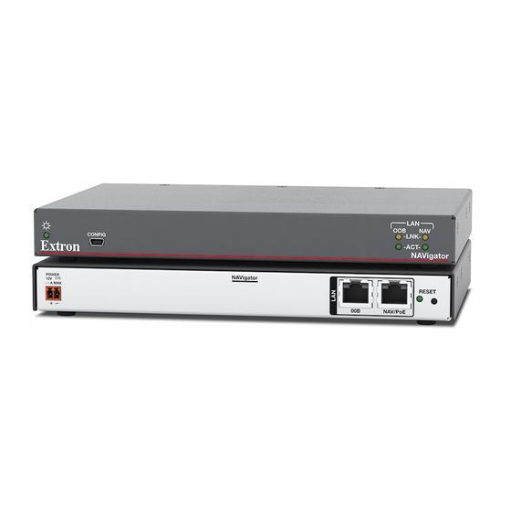
Figure 1.
NAVigator Rear Panel Features
A
Power connector (optional) — Plug the included external 12 VDC power supply into this 2-pole
connector for local power. See the drawing at right to wire the connector and
power options.
NOTE:
Alternatively, the NAVigator can be powered via PoE, from the network switch or
using an optional PI 140 Power Injector.
B
NAV/PoE port — Connect this port to your AV LAN network for connection to streaming endpoints
(NAV encoders and decoders), as well as management and control devices. This port can also receive
Power over Ethernet (PoE) to power the NAVigator. Streaming endpoints must be on the same network
as the NAV/PoE port.
C
OOB (Out of Band) port — Connect this port to the Out of Band network for remote management and
configuration of the NAV system. The OOB port cannot receive PoE.
NOTE:
The OOB network is a secure boundary from the in-band NAV network. The OOB port allows for
a secure web interface and secure control of the NAVigator.
D
Reset button and LED — Press this button and observe the LED to initiate three modes of NAVigator reset
(see the NAVigator User Guide, available at www.extron.com).
Step 3 — Front Panel Configuration Port Connection
CONFIG
e
B B
B
A
A A
Figure 2.
NAVigator Front Panel Features
A
Configuration port — Connect a PC or other controlling device into the NAVigator via this front panel mini-B USB connector for
configuration of the NAVigator and NAV system. The port uses IP over USB technology; the IP address is always 203.0.113.22 and
CANNOT be changed.
OOB
C
C C
Smooth
Power
on page 2 for
SECTION A–A
Power Supply
Output Cord
NAVigator
RESET
NAV/PoE
B B
B
D D
D
Ridges
Captive
Screw
Connector
3"
16 (5 mm) MAX
A
A
Pins:
TIA/EIA T
12345678
568B
Pin
Wire color
1
White-orange
2
Orange
3
White-green
4
Blue
5
White-blue
Green
6
7
White-brown
8
Brown
TP Wires
LAN
00 B
NAV
LNK
ACT
NAVigator
C C
C
1
Advertisement

Related Manuals for Extron electronics NAVigator


Summary of Contents for Extron electronics NAVigator
- Page 1 NAVigator Front Panel Features Configuration port — Connect a PC or other controlling device into the NAVigator via this front panel mini-B USB connector for configuration of the NAVigator and NAV system. The port uses IP over USB technology; the IP address is always 203.0.113.22 and...
-
Page 2: Operation
When power is applied, the NAVigator runs a series of self-tests that blink the front panel Power LED and all other indicators. The NAVigator then boots the NAV operating system. It can take approximately 45 seconds for self-test and system startup to complete. When the process is complete, the Power LED lights steadily. - Page 3 • The factory configured passwords for all accounts on this device have been set to the device serial number. If the password is reset, the NAVigator defaults to the default password, which is extron. • Usernames and passwords are case sensitive.
-
Page 4: Network Connection Settings
2 2 2 2 2 2 2 2 2 2 2 2 Figure 5. Home Page Detailed descriptions of communication, configuration, monitoring are provided in the NAVigator User Guide, available at NOTE: www.extron.com. Network Connection settings View and change connection settings as follows: On the home page, if necessary, click the Menu link (see figure 5, ). - Page 5 2 2 2 2 2 2 2 2 2 2 2 2 2 2 2 2 2 2 3 3 3 3 3 3 3 3 3 3 3 3 3 3 3 3 3 3 1 1 1 1 1 1 1 1 1 1 1 1 1 1 1 1 1 1 Figure 7.
- Page 6 NAVigator • Setup Guide (Continued) Discover and assign encoders and decoders Discover and assign encoders and decoders (endpoints) to the NAV system as follows: You can also pair encoders and decoders to each other using the device ID buttons on the endpoints (see the applicable NOTE: encoder and decoder guides available at www.extron.com).
- Page 7 Assign Endpoints Click the All checkbox (see figure 10, ) or individual endpoint checkboxes ( Click Assign ( ). The NAVigator assigns the endpoints and reports success on the endpoints panel. Configure selected endpoint communication settings Configure endpoints as follows:...
- Page 8 NAVigator • Setup Guide (Continued) 1 1 1 1 1 1 1 1 1 1 1 1 1 1 1 1 1 1 3 3 3 3 3 3 3 3 3 3 3 3 3 3 3 3 3 3...
- Page 9 Configure other endpoint settings The HTML pages of an endpoint can be opened via the NAVigator for additional endpoint configuration, as follows: On the Endpoints page (see figure 14), click in the field for the connected endpoint ( ). The HTML page opens a Device Details side panel to the right of the Endpoints panel.
- Page 10 For information on safety guidelines, regulatory compliances, EMI/EMF compatibility, accessibility, and related topics, see the Extron Safety and Regulatory Compliance Guide on the Extron website. © 2019 Extron Electronics — All rights reserved. www.extron.com 68-2740-50 Rev. A All trademarks mentioned are the property of their respective owners.
Need help?
Do you have a question about the NAVigator and is the answer not in the manual?
Questions and answers