
Related Manuals for ETAS ETK-S6.0


Summary of Contents for ETAS ETK-S6.0
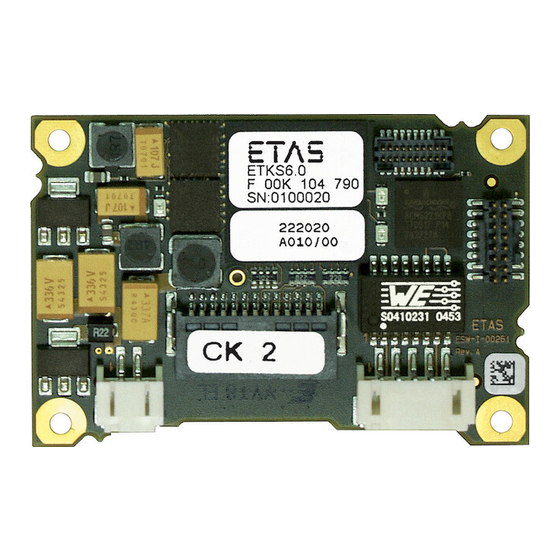
- Page 1 ETK-S6.0 Emulator Probe for Renesas AUD-II and H-UDI Debug Interface User’s Guide...
- Page 2 The data in this document may not be altered or amended without special noti- fication from ETAS GmbH. ETAS GmbH undertakes no further obligation in rela- tion to this document. The software described in it can only be used if the customer is in possession of a general license agreement or single license.
-
Page 3: Table Of Contents
ETK-S6.0 Subtypes ........ - Page 4 ETAS Hardware ........
- Page 5 10 ETAS Contact Addresses ........
-
Page 6: About This Manual
Goal definition: any advance information... • Step 1 Any explanation for step 1... • Step 2 Any explanation for step 2... • Step 3 Any explanation for step 3... Any concluding comments... ETK-S6.0 - User’s Guide... -
Page 7: Scope Of Supply
(see chapter "Order- ing Information"). Additional cables and adapters can be obtained separately from ETAS. A list of accessories and their order designation is available in this manual and at the ETAS Home Page. -
Page 8: Basic Safety Notices
• "Declarable Substances" on page 13 • "Use of Open Source Software" on page 13 General Safety Information Please observe the Product Safety Notices ("ETAS Safety Notice") and the follow- ing safety notices to avoid health issues or damage to the device. Note Carefully read the documentation (Product Safety Advice and this User's Guide) that belongs to the product prior to the startup. - Page 9 The product is designed in accordance with state-of-the-art technology and rec- ognized safety rules. The product may be operated only in a technically flawless condition and according to the intended purpose and with regard to safety and ETK-S6.0 - User’s Guide...
- Page 10 Cabling Use exclusively ETAS cables at the connections of the product! Adhere to the maximum permissible cable lengths! Observe the assignment of the cables to the connectors! Detailed information about cabling is located in the ETK User's Guides.
-
Page 11: Identifications On The Product
SN: yyxxxxx Serial number (7-digit) XXXX/YY Product version ZZZZ Year of manufacture ETAS GmbH, Manufacturer's address PO Box 300220, 70442 Stuttgart, Germany Note For symbols and product information one or several adhesive labels can be used. ETK-S6.0 - User’s Guide... -
Page 12: Taking The Product Back And Recycling
CE marking With the CE mark attached to the product or its packaging, ETAS confirms that the product corresponds to the applicable product-specific European Directives. The CE Declaration of Conformity for the product is available upon request. -
Page 13: Declarable Substances
Some products from ETAS GmbH (e.g. modules, boards, cables) use components with substances that are subject to declaration in accordance with the REACH regulation (EU) no.1907/2006. Detailed information is located in the ETAS download center in the customer information "REACH Declaration" (www.etas.com/Reach). This information is continuously being updated. -
Page 14: Introduction
Renesas H-UDI interface Fig. 3-1 ETK-S6.0 (left: Rev. A, right: Rev. B) Note The ETK-S6.0 can be shipped in the mechanical versions revision A and revision B. Both ETK-S6.0 versions have the same features, functions and technical data. Both mechanical versions can be configured to use the ECU interface either as an AUD-II interface or as an H-UDI interface. - Page 15 • The interface voltage level is 3.3 V. The supervisor voltage level is config- urable • Temperature range suitable for automotive application For more technical data on the ETK-S6.0 refer the chapter "Technical Data" on page 38. ETK-S6.0 - User’s Guide...
-
Page 16: Hardware Description
The microcontroller can communicate with the memories or peripheral compo- nents of the development ECU. The ETK-S6.0 is connected to the serial debug and test interface of the microcon- troller (AUD-II or H-UDI). It converts these interface to the 100 MBit/s serial ETK interface and extends in this way the length of the connection line. -
Page 17: Ecu Interface
ETK-S6.0 from the ECU. The ETK-S6.0 is connected to the ECU via an adapter cable with 26 pins, where the pin definition depends on the application and the microcontroller type. -
Page 18: H-Udi Interface
In general the ECU interface configured for H-UDI operation (ETK-S6.0 configu- ration subtype B, see chapter 6.3 on page 33) consists of • 8 AUD-II lines for the communication between the ETK-S6.0 and the ECU microcontroller • 5 JTAG interface lines which are fed to a separate connector for connec- tion of an external debugger ETK-S6.0 - User’s Guide... -
Page 19: Fig. 4-4 Usage Of Level Shifter Ics
(refer to chapter 4.6 on page 22) – 6 ground lines for a proper shielding of the ECU interface lines. If the debug interface lines between the ETK-S6.0 and the ECU microcontroller are configured as an H-UDI interface at least two GPIO pins are required: the usage of the DAI1/ DAI2 signals is mandatory, if more trigger options are required the DAI3/ DAI4 signals can be additionally applied. -
Page 20: Serial Etk Interface
Fig. 4-5 Usage of diodes and resistors Serial ETK Interface The serial 100 Mbit/s ETK-S6.0 interface creates the link to the calibration and development system. The interface utilizes a 100Base-TX transmission to achieve a transmission performance of 100 Mbit/s. To ensure stable communication only 100 Mbit cables delivered by ETAS shall be used. -
Page 21: Debug Interface
By using the AUD-II interface for serial ETK connection, it is not available for debugging tools anymore. Therefore a feedthrough for a second debugger inter- face (JTAG) is provided. This enables parallel use of tools for debugging and ETAS tools for measurement and calibration. -
Page 22: Power Supply
Power Supply Connectors CON2 and CON3 (left: Rev. A, right: Rev. The ETK-S6.0 needs a permanent power supply. It is powered directly from the car battery. The input voltage may vary between 4.3 V and 18 V. In case of higher input voltages to the ETK an additional voltage converter is required. -
Page 23: Status Leds
ETAS Hardware Description Status LEDs There are three LEDs displaying the operating status of the ETK-S6.0 (Fig. 4-10 on page 23). Fig. 4-10 Status LEDs (left: Rev. A, right: Rev. B) State Definition ETK-S6.0 is supplied with power and active (i.e. the ECU is... -
Page 24: Startup, Trigger And Reset
The value of the pattern is dependent on the detection of a power fail of the ECU standby power supply by the ETK-S6.0. In the case of power failure the calibration RAM content has not been restored by the ETK. When the reset signal is de-asserted the CPU latches the AUDATA[3..0] value into a special register... -
Page 25: Phases Of The Startup Protocol For H-Udi Operation
4.10.2 Phases of the Startup Protocol for H-UDI Operation If the ETK-S6.0 is configured in the ETK Configuration Tool as "ETK-S6.0 Config- uration B" (see chapter 6.4 on page 34) the ETK is activated for H-UDi operation. During the startup phase the ETK and the ECU exhibit a well defined startup procedure. -
Page 26: Fig. 4-12 Startup Procedure In Detail
There are different reset detection levels of ECU and ETK with resulting uncer- tainty t Reset ECU reset det ect ion level ETK reset det ect ion level DAI1 DAI2 Fig. 4-12 Startup Procedure in Detail The condition for proper operation is: << t << t HOLD ETK-S6.0 - User’s Guide... -
Page 27: Triggering Of Measurement Data Acquisition
ECU is clean and smooth. The ETK-S6.0 normally drives /RES low during ECU power up or upon INCA request. The signal /RES of the microprocessor is used by the ETK-S6.0 to detect when the ECU is in reset. ETK-S6.0 - User’s Guide... - Page 28 To adapt the ETK detection scheme to different system architectures the reset detection delay of the ETK-S6.0 is configurable: either a short delay of 2 μs or an extended delay of 30 μs can be selected via configuration feature. The result is that the ETK detection pattern is applied to the AUDATA lines for a short period of time after the reset has been de-asserted.
-
Page 29: Installation
ETK printed circuit board. For connecting the ETK-S6.0 to the ECU the ETK adapter ETAF1 is recom- mended. It need to be ordered seperately (refer chapter "Ordering Information" on page 58).The suitable connector [ERNI 064320] should have been populated onto the ECU PCB. -
Page 30: Connection To The Debugger
ETK-S6.0 Connection to the ECU and to the Debugger Connection to the Debugger For connecting the ETK-S6.0 to the debugger the ETK adapter ETAF6 (including ETAF6 PCB and ETAF6 flatcable) is required. Its needs to be ordered seperately (refer chapter "Ordering Information" on page 58). A debugger specific cable has to be used to connect the debugger with the ETAF6 PCB. -
Page 31: Connecting To The Power Supply
ETAS Installation Connecting to the Power Supply The ETK-S6.0 needs a permanent power supply (refer chapter "Power Supply" on page 22). There are different versions to ensure it. 5.3.1 Permanent Power Supply inside ECU available Pow er Supply Connect or... -
Page 32: Isolated Power Supply Inside Ecu
ETAS Installation 5.3.3 Isolated Power Supply inside ECU The ETK-S6.0 does not require a galvanically isolated power supply. For special applications ETAS offers the isolated power supply ETP2. Pow er Supply Connect or Permanent Supply Isolat ed Pow er Supply... -
Page 33: Etk Configuration
ETAS ETK Configuration ETK Configuration In this chapter, the configuration parameters of the ETK-S6.0 are described. Overview As already mentioned in previous chapters, some project-specific adjustments are necessary. Configuration data is stored permanently in a serial E²PROM. ETK Configuration Tool Generating a valid configuration data set is supported by the "ETK Configuration... -
Page 34: Configuration Parameter
The following is a list with configuration parameters. 6.4.1 Subtype ETK-S6.0A In this setting the ETK-S6.0 uses the AUD interface to interface the microcontrol- ler. • Microcontroller (SH72544, SH72544R, SH72546RFCC, SH72567BFCC) The memory layout of these microcontrollers differs significantly, so the ETK Configuration Tool needs know which one is used. -
Page 35: Subtype Etk-S6.0B
ETK by the ECU. 6.4.2 Subtype ETK-S6.0B In this setting the ETK-S6.0 uses the JTAG H-UDI interface to interface the micro- controller. • Microcontroller (SH72531F, SH72531FCC, SH72533FCC) The default value is "SH72531FCC". - Page 36 The level for the level supervision of the ECU RAM Standby can be set here. To display the properties of the used voltage comparators the Low High and High Low thresholds are shown as well. ETK-S6.0 - User’s Guide...
- Page 37 ETK. The key code can be specified within the "ETK Configuration Tool" window "ETK Hardware". We recommend to program the ECU with "0xFFFF FFFF FFFF FFFF" as key code. In this case the ECU accepts any key code. ETK-S6.0 - User’s Guide...
-
Page 38: Technical Data
ETAS Technical Data Technical Data Note The ETK-S6.0 can be shipped in the mechanical versions revision A and revision B. Both ETK-S6.0 versions have the same features, functions and technical data. System Requirements This section tells you which hardware and software are needed to operate your ETK-S6.0 and which microcontrollers are supported. -
Page 39: Environmental Conditions
Operating Current I = 12 V; Batt Batt ECU on; T = 20 °C 1) The ETK-S6.0 implements reverse voltage protection in the same range and may be used only with central load dump protection. Memory 7.4.1 Data Emulation Memory... -
Page 40: Configuration
- memory configurations stored in EEPROM Update Logic devices updated through soft- ware Serial ETK Interface for Application System Item Characteristics Transmission speed 100 Mbit/s Cable length max. 30 m / 100 ft Serial Interface DC decoupling ETK-S6.0 - User’s Guide... -
Page 41: Testcharacteristics
: max. delay of ECU reset through ETK (U and USG will be switched on) Batt : configurable : generated by ETK if ETK is operating in H-UDI mode (configuration B) : for attached debugger : must be less than periphal clock P ETK-S6.0 - User’s Guide... -
Page 42: Ecu Interface Characteristics
7.7.1 ECU Interface Characteristics Parameter Symbol Condition Unit USG ECU Power Supply Supervision 2.48 2.58 2.68 Voltage (3.3 V, USG 2.33 2.43 2.53 treshold Low -> High = 2.33 V, USG = 2.68 V μA treshold High -> Low = 2.68 V selected) USG ... -
Page 43: Electrical Characteristics
Adapter cable and Samtec connector not considered; PCB 1 pF/cm at USG = 3.0 V (USG configured at 3.3 V) at /RES = Low at /RES = High Open Drain FET; I = 0.2 A, V = 0.45 V Dmax OL(max) ETK-S6.0 - User’s Guide... -
Page 44: Debug Interface Connector Con5
Technical Data 7.8.2 Debug Interface Connector CON5 TMS, +495 -225 /TRST -495 -225 AUDCK, /ASEBRKAK /DETECT -240 Adapter cable and Samtec connector not considered; PCB 1 pF/cm at USG = 3.0 V (USG configured at 3.3 V) ETK-S6.0 - User’s Guide... -
Page 45: Pin Assignment
ETAS Technical Data Pin Assignment 7.9.1 ECU Interface Connector CON1 (ETK-S6.0 Configuration A) Signal Direc- Comment tion /AUDSYNC AUD-II signal /ASCBRKAK Debugger break signal Not connected AUDCK AUD-II clock signal JTAG signal JTAG signal JTAG signal JTAG signal USGSTBY Comparator input... -
Page 46: Ecu Interface Connector Con1 (Etk-S6.0 Configuration B)
ETAS Technical Data 7.9.2 ECU Interface Connector CON1 (ETK-S6.0 Configuration B) Signal Direc- Comment tion Reserved /ASEBRKAK Feed-through to debugger Not connected Reserved JTAG signal JTAG signal JTAG signal JTAG signal USGSTBY Comparator input (Sense) Standby (permanent) power supply of ECU... -
Page 47: Power Supply Connector Con2
Technical Data 7.9.3 Power Supply Connector CON2 CON1 CON1 CON2 CON4 CON2 CON4 Fig. 7-1 Power Supply Connector CON2 (left: Rev. A, right: Rev. B) Pin CON2 Signal Description Battery Supply Voltage for ETK Batt Ground ETK-S6.0 - User’s Guide... -
Page 48: Debug Interface Connector Con5
AUDCK AUD-II clock Signal Ground TDI to target /RES /Reset to target /TRST /TRST to target /ASEBRKAK /Break signal from target TCLK TCLK to target Signal Ground Not connected /DETECT Debugger detect signal Not connected Reserved3 ETK-S6.0 - User’s Guide... -
Page 49: Mechanical Dimensions
ETAS Technical Data 7.10 Mechanical Dimensions The reference measure for all drawings is millimeter. Fig. 7-2 ETK-S6.0 Dimensions - Top View (left: Rev. A, right: Rev. B) Dimen- Millimeters Inches Dimen- Millimeters Inches sion sion 60.00 2.362 3.00 0.118 56.50 2.224... -
Page 50: Cables And Accessories
12.50 0.492 400.00 15.748 160.00 6.299 19.00 0.748 Note Shield connected to ECU housing. SKINDICHT compact screwing; Manufacturer: Lapp; Description: SH7; Order-No.: 5200 0830 Nut for compact screwing; Manufacturer: Lapp; Description: SM7; Order-No.: 5200 3490 ETK-S6.0 - User’s Guide... -
Page 51: Fig. 8-2 Interface Cable Ka54, Proposal 2
0.185 12.00 0.472 27.00 1.063 Note Shield connected to ECU housing. SKINTOP compact screwing; Manufacturer: Lapp; Description: MS-SC 11 ; Order-No.: 5311 2320 Nut for compact screwing; Manufacturer: Lapp; Description: SM-PE 11 ; Order-No.: 5210 3220 ETK-S6.0 - User’s Guide... -
Page 52: Cable Ka41
Fig. 8-3 Interface Cable KA41, Proposal 1 Millimeters Inches 13.90 0.547 12.30 0.484 140.00 5.512 20.00 0.787 16.20 0.636 Note Shield not connected to ECU housing. Cable KA41, Proposal 2 Fig. 8-4 Interface Cable KA41, Proposal 2 ETK-S6.0 - User’s Guide... -
Page 53: Cable Ka55
Strain relief on ECU cover necessary. Shield not connected to ECU housing. 8.1.4 Cable CBAM200 Fig. 8-6 Interface Cable CBAM200-0m38 Millimeters Inches 380.00 14.96 30.00 1.18 Note Shield connected to ECU housing, allows for ECU housing flush mounting. ETK-S6.0 - User’s Guide... -
Page 54: Power Supply Cables
Millimeters Inches 190.00 7.480 8.2.2 Cable with Filtercoil ETV2 Fig. 8-8 Power Supply Cable with Filtercoil ETV2 Millimeters Inches 190.00 7.480 50.00 1.969 8.2.3 Cable K70 Fig. 8-9 Power Supply Cable K70 Millimeters Inches 2000 78.74 ETK-S6.0 - User’s Guide... -
Page 55: Cable Ka50
ETAS Cables and Accessories 8.2.4 Cable KA50 Fig. 8-10 Power Supply Cable KA50 Millimeters Inches 7.87 1.97 8.2.5 Cable CBM200 Fig. 8-11 Power Supply Cable CBM200 Millimeters Inches 3.94 ETK-S6.0 - User’s Guide... -
Page 56: Adapters
ETAS Cables and Accessories Adapters 8.3.1 ETK - ECU Adapter ETAF1 Fig. 8-12 ETK - ECU Adapter ETAF1 Millimeters Inches 100.00 3.94 8.3.2 Debug Adapter ETAF6 ETAF6 Flatcable Fig. 8-13 ETAF6 Flatcable Millimeters Inches 50.80 2.00 ETK-S6.0 - User’s Guide... -
Page 57: Fig. 8-14 Etaf6 - Mechanical Dimensions And Component Placement
ETAF6 PCB CO103 CO101 CO102 CO100 Fig. 8-14 ETAF6 - Mechanical Dimensions and Component Placement Millimeters Inches 35.00 1.38 32.00 1.26 1.60 0.06 Connector Description C0100 to ETK Debug Connector C0101 to Debugger C0102 to ECU ETK-S6.0 - User’s Guide... -
Page 58: Ordering Information
Power Supply Interface for ETK ETP2 F 00K 104 010 Cables Please contact your local ETAS representative for further cable information. Note The cables showed in chapter "Cables and Accessories" on page 50 are not included in the ETK-S6.0 delivery. -
Page 59: Interface Cables
Y 261 A24 942 Lemo 0B FGG # open wires (2fc-1c), 2 m ETK Power Supply Cable for External Sup- KA50 F 00K 000 940 ply, with Filter Coil, Lemo 0B EGG # open wire (2fc-1c), 0m2 ETK-S6.0 - User’s Guide... -
Page 60: Etas Contact Addresses
Germany WWW: www.etas.com ETAS Subsidiaries and Technical Support For details of your local sales office as well as your local technical support team and product hotlines, take a look at the ETAS website: ETAS subsidiaries WWW: www.etas.com/en/contact.php ETAS technical support WWW: www.etas.com/en/hotlines.php... -
Page 61: Figures
Fig. 7-1 Power Supply Connector CON2 (left: Rev. A, right: Rev. B)......47 Fig. 7-2 ETK-S6.0 Dimensions - Top View (left: Rev. A, right: Rev. B) ......49 Fig. 7-3 Mechanical Dimensions ETK-S6.0: Microcontroller with Socket Adapter mounted ....................49 Fig. - Page 62 Power Supply Cable KA50 ................. 55 Fig. 8-11 Power Supply Cable CBM200 ..............55 Fig. 8-12 ETK - ECU Adapter ETAF1 ................56 Fig. 8-13 ETAF6 Flatcable ..................56 Fig. 8-14 ETAF6 - Mechanical Dimensions and Component Placement....... 57 ETK-S6.0 - User’s Guide...
-
Page 63: Index
Debug 21 Data Emulation Memory 39 ECU 17 Data Measurement 23 ETK 20 Debug Adapters 58 Serial 20 Documentation 8 Interface Cables 50 Introduction 14 Isolated Power Supply 32 ECU Interface 17 ECU Interface Characteristics 42 ETK-S6.0 - User’s Guide... - Page 64 PC interface 38 Reset 27 RoHS conformity China 12 European Union 12 Safety notices Identification 6 Safety precautions 8 Scope of supply 7 Serial ETK Interface 20 Startup Protocol, Phases of 24 Status LED 23 Supported Microcontrollers 17 ETK-S6.0 - User’s Guide...
Need help?
Do you have a question about the ETK-S6.0 and is the answer not in the manual?
Questions and answers