Table of Contents
Advertisement
Quick Links
Advertisement
Table of Contents

Related Manuals for ETAS ES4105.2


Summary of Contents for ETAS ES4105.2
- Page 1 ES4105.2 Housing User’s Guide...
- Page 2 Copyright The data in this document may not be altered or amended without special notification from ETAS GmbH. ETAS GmbH undertakes no further obligation in relation to this document. The software described in it can only be used if the customer is in possession of a general license agreement or single license.
-
Page 3: Table Of Contents
Contents 1 Introduction ........... . . 5 Features . - Page 4 5 Technical Data ..........15 Index .
-
Page 5: Introduction
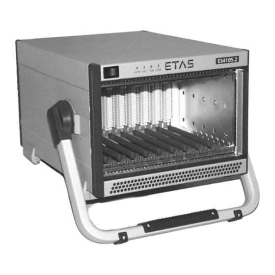
Introduction This section contains information about the basic features and applications of the ES4105.2 Housing. Features The ES4105.2 Housing is a compact housing for VME boards. It has the follow- ing features: • 10 slots • standard VMEbus and VME64x boards •... - Page 6 Introduction...
-
Page 7: Functional Description
Tab. 2-1 Display on the Front Panel Slots The ES4105.2 Housing provides 10 slots at intervals of 4 HP. The slots are designed for standard Eurocards in 100 mm x 160 mm size. The front panel height of the plug-in boards measures 3 U. - Page 8 Functional Description...
-
Page 9: Operation
Operation This section provides information about the installation and removal of the VMEbus boards, fuse replacement, and automatic overcurrent protection of the housing. Installation of VMEbus Boards Some VMEbus boards need to be configured before they can be installed. The corresponding information can be found in the manuals of the VMEbus board. -
Page 10: Fuse Replacement
2. Disconnect all connectors from the board you want to remove. 3. Loosen the mounting screws at the top and bot- tom edge of the board’s front panel. 4. Grasp the handle of the board and pull the board carefully out. 5. - Page 11 3. Turn the power to the housing back on. note If the automatic overcurrent protection cannot be reset, check the fuses at the rear of the housing. A main fuse is defective if the control lamp in the power switch remains dark even when power has been switched on. Operation...
- Page 12 Operation...
-
Page 13: Connectors
Connectors This section contains information about the pin allocation of the connectors. VME64x The boards are connected using 160-pin VG multi-point connectors. The pins in rows a, b, and c correspond to the standard VMEbus. Row z Row a Row b Row c Row d /BBSY... -
Page 14: Battery Ground
Row z Row a Row b Row c Row d /IRQ5 +3.3 V RsvBus /IRQ4 LI-/I /IRQ3 +3.3 V RsvBus /IRQ2 LI-/O /IRQ1 +3.3 V RsvBus -12 V +5 V Stby +12 V +5 V +5 V +5 V Tab. 4-1 Pin Allocation VME64x (cont.) Battery Ground The GND of the VMEbus can be connected with an external ground (-UBatt) - Page 15 Technical Data This section contains the technical data of the ES4105.2 Housing in tabular form. General Data Mechanical structure Case with tip-up/carrying handle Slots 10 slots at 4 HP intervals for standard Eurocards (100 mm x 160 mm) Mechanical Data Height 4 U (177.2 mm)
- Page 16 Backplane Standard VME64x Number of pins 160 per slot Compatibility Standard VMEbus VME64x Termination Passive Additional Connectors Battery Ground on the rear of the housing Quantity Mode permanent Air flow, free air 84 m Environmental Conditions Operating temperature 0 °C to 70 °C (32 °F to 158 °F) Storage temperature -55 °C to +85 °C (-67 °F to 185 °F) Operating humidity...
- Page 17 Index Backplane 16 Operation 9 Battery Ground 14 Output voltage 15 Board Overcurrent protection 10 installation 9 Power supply unit 15 Connectors 13 Removal Data board 9 mechanical 15 Resetting technical 15 overcurrent protection 10 Environmental conditions 16 Supply voltage 15 Fan 16 Technical data 15 Features 5...
- Page 18 Index...
Need help?
Do you have a question about the ES4105.2 and is the answer not in the manual?
Questions and answers