Sign In
Upload
Manuals
Brands
ETAS Manuals
Computer Hardware
ETK-S6.0
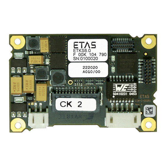
User Manuals: ETAS ETK-S6.0 ECU Interface
Manuals and User Guides for ETAS ETK-S6.0 ECU Interface. We have
1
ETAS ETK-S6.0 ECU Interface manual available for free PDF download: User Manual
ETAS ETK-S6.0 User Manual (64 pages)
Emulator Probe for Renesas AUD-II and H-UDI Debug Interface
Brand:
ETAS
| Category:
Computer Hardware
| Size: 1 MB
Table of Contents
Table of Contents
3
1 About this Manual
6
Identification of Safety Notices
6
Presentation of Information
6
Scope of Supply
7
Additional Information
7
2 Basic Safety Notices
8
General Safety Information
8
Requirements for Users and Duties for Operators
8
Intended Use
8
Identifications on the Product
11
Fig. 2-1 Adhesive Label (Example: Label for XETK-S14.0)
11
Taking the Product Back and Recycling
12
CE Marking
12
Rohs Conformity
12
European Union
12
China
12
Fig. 2-2 WEEE-Symbol
12
Declarable Substances
13
Use of Open Source Software
13
3 Introduction
14
Applications
14
Features
14
Fig. 3-1 ETK-S6.0 (Left: Rev. A, Right: Rev. B)
14
4 Hardware Description
16
Architecture
16
ETK-S6.0 Subtypes
16
Fig. 4-1 ETK-S6.0 Architecture
16
ECU Interface
17
AUD-II Interface
17
Fig. 4-2 Location of the ECU Interface (Left: Rev. A, Right: Rev. B)
17
H-UDI Interface
18
Fig. 4-3 Equivalent Circuitry of the AUD-II Interface
18
Fig. 4-4 Usage of Level Shifter Ics
19
Serial ETK Interface
20
Fig. 4-5 Usage of Diodes and Resistors
20
Fig. 4-6 Location of the Serial ETK Interface (Left: Rev. A, Right: Rev. B)
20
Debug Interface
21
Fig. 4-7 Location of the Debugger Interface (Left: Rev. A, Right: Rev. B)
21
Fig. 4-8 Equivalent Circuitry of the ECU JTAG Interface (ECU)
21
Power Supply
22
ECU Voltage Supervisor
22
Fig. 4-9 Power Supply Connectors CON2 and CON3 (Left: Rev. A, Right: Rev. B)
22
Status Leds
23
Data Emulation and Data Measurement
23
Fig. 4-10 Status Leds (Left: Rev. A, Right: Rev. B)
23
Startup, Trigger and Reset
24
Phases of the Startup Protocol for AUD-II Operation
24
Phases of the Startup Protocol for H-UDI Operation
25
Fig. 4-11 Phases of the Startup Protocol
25
Fig. 4-12 Startup Procedure in Detail
26
Triggering of Measurement Data Acquisition
27
Reset
27
5 Installation
29
Connection to the ECU
29
Fig. 5-1 ETK-S6.0 Connection to the ECU
29
Connection to the Debugger
30
Fig. 5-2 ETK-S6.0 Connection to the ECU and to the Debugger
30
Connecting to the Power Supply
31
Permanent Power Supply Inside ECU Available
31
Permanent Power Supply Inside ECU Not Available
31
Fig. 5-3 Permanent Power Supply Inside ECU Available
31
Fig. 5-4 Permanent Power Supply Inside ECU Not Available
31
Isolated Power Supply Inside ECU
32
Fig. 5-5 Isolated Power Supply Inside ECU
32
6 ETK Configuration
33
Overview
33
ETK Configuration Tool
33
ETK-S6.0 Subtypes
33
Configuration Parameter
34
Subtype ETK-S6.0A
34
Subtype ETK-S6.0B
35
7 Technical Data
38
System Requirements
38
ETAS Hardware
38
Software
38
Environmental Conditions
39
Power Supply
39
Memory
39
Data Emulation Memory
39
Measurement Data Memory
39
Configuration
40
Serial ETK Interface for Application System
40
Testcharacteristics
41
ECU Interface Characteristics
42
Electrical Characteristics
43
ECU Interface Connector CON1
43
Debug Interface Connector CON5
44
Pin Assignment
45
ECU Interface Connector CON1 (ETK-S6.0 Configuration A)
45
ECU Interface Connector CON1 (ETK-S6.0 Configuration B)
46
Power Supply Connector CON2
47
Fig. 7-1 Power Supply Connector CON2 (Left: Rev. A, Right: Rev. B)
47
Debug Interface Connector CON5
48
Mechanical Dimensions
49
Fig. 7-2 ETK-S6.0 Dimensions - Top View (Left: Rev. A, Right: Rev. B)
49
Fig. 7-3 Mechanical Dimensions ETK-S6.0: Microcontroller with Socket Adapter Mounted
49
8 Cables and Accessories
50
Interface Cables
50
Cable KA54 (with PG Cable Gland)
50
Fig. 8-1 Interface Cable KA54, Proposal 1
50
Fig. 8-2 Interface Cable KA54, Proposal 2
51
Cable KA41
52
Fig. 8-3 Interface Cable KA41, Proposal 1
52
Fig. 8-4 Interface Cable KA41, Proposal 2
52
Cable KA55
53
Cable CBAM200
53
Fig. 8-5 Interface Cable KA55
53
Fig. 8-6 Interface Cable CBAM200-0M38
53
Power Supply Cables
54
Cable ETV
54
Cable with Filtercoil ETV2
54
Cable K70
54
Fig. 8-7 Power Supply Cable ETV
54
Fig. 8-8 Power Supply Cable with Filtercoil ETV2
54
Fig. 8-9 Power Supply Cable K70
54
Cable KA50
55
Cable CBM200
55
Fig. 8-10 Power Supply Cable KA50
55
Fig. 8-11 Power Supply Cable CBM200
55
Adapters
56
ETK - ECU Adapter ETAF1
56
Debug Adapter ETAF6
56
Fig. 8-12 ETK - ECU Adapter ETAF1
56
Fig. 8-13 ETAF6 Flatcable
56
Fig. 8-14 ETAF6 - Mechanical Dimensions and Component Placement
57
9 Ordering Information
58
Etk-S6.0
58
Connector ECU - ETK Adapter ETAF1
58
Adapters
58
Debug Adapters
58
Power Supply
58
Cables
58
Interface Cables
59
Power Supply Cables
59
10 ETAS Contact Addresses
60
Figures
61
Index
63
Advertisement
Advertisement
Related Products
ETAS ETK-S21.1
ETAS ETK-S9.0
ETAS ETK-S20.1
ETAS ES5352.1
ETAS ES5340.2
ETAS ES1231.2-A
ETAS ES4602
ETAS ES4450
ETAS ES4451
ETAS ES4455
ETAS Categories
Control Unit
Computer Hardware
Measuring Instruments
Recording Equipment
I/O Systems
More ETAS Manuals
Login
Sign In
OR
Sign in with Facebook
Sign in with Google
Upload manual
Upload from disk
Upload from URL