Table of Contents
Advertisement
Quick Links
This user's guide presents an overview of the DLP3010 Light Control evaluation module (EVM) and a
general description of the main features and functions. It explains the first steps to get started, and shows
a detailed description of the push buttons function, the on board LEDs, and the main connectors.
1
2
3
4
5
6
7
....................................................................................................................
8
1
2
3
4
5
6
7
8
1
2
3
4
5
6
DLPU070B - July 2018 - Revised February 2019
Submit Documentation Feedback
DLP3010 Light Control EVM User's Guide
...................................................................................
..........................................................................................................
......................................................................................................
..................................................................................................................
.......................................................................................................
...........................................................................................................
...................................................................................
....................................................................................
.......................................................................................
....................................................................................
............................................................................................................
.................................................................................
..............................................................................................
......................................................................................
Copyright © 2018-2019, Texas Instruments Incorporated
DLPU070B - July 2018 - Revised February 2019
Contents
............................................................................
List of Figures
............................................................................
.............................................................................
List of Tables
...............................................................................
.....................................................................
..................................................
.............................................................................
DLP3010 Light Control EVM User's Guide
User's Guide
2
3
3
4
5
5
7
9
2
4
5
6
9
10
10
11
5
6
7
7
7
8
1
Advertisement
Table of Contents

Subscribe to Our Youtube Channel
Related Manuals for Texas Instruments DLP3010


Summary of Contents for Texas Instruments DLP3010
-
Page 1: Table Of Contents
DLP3010 Light Control EVM User’s Guide This user’s guide presents an overview of the DLP3010 Light Control evaluation module (EVM) and a general description of the main features and functions. It explains the first steps to get started, and shows a detailed description of the push buttons function, the on board LEDs, and the main connectors. -
Page 2: Dlp3010 Light Control Evm Overview
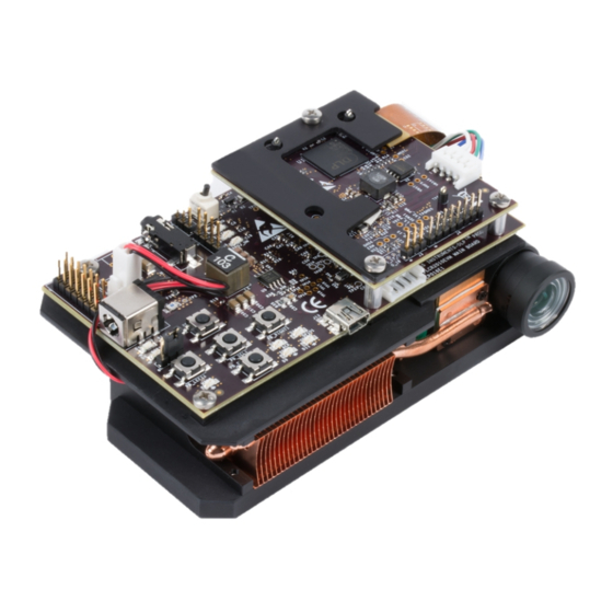
DLP3010 Light Control EVM Overview This DLP3010 Light Control EVM includes an example light engine design composing of DLP electronics and optics along with GUI software to provide a flexible light steering solution with high brightness and resolution for industrial, medical and scientific applications. This EVM features DLP3010, DLPC3478 and DLPA2005 DLP components and offers a compelling combination of resolution, brightness, and programmability in a small form factor. -
Page 3: Safety Instructions
Always ensure both fans are running during operation to avoid overheating and ensure reliable operation. Applicable Documents The following documents are applicable to the DLP3010 Light Control EVM and are available at TI.com (www.ti.com). • DLP3010 (0.3 720p) DMD data sheet (DLPS051) •... -
Page 4: What Is In The Dlp3010 Light Control Evm
What is in the DLP3010 Light Control EVM? www.ti.com What is in the DLP3010 Light Control EVM? The DLP3010 Light Control module consists of three subsystems: • Light engine – includes the optics, red, green, and blue LEDs, and a 1280 × 720 (720p) DMD •... -
Page 5: Light Engine
This quick-start assumes default conditions as shipped. 1. Power up the DLP3010 Light Control EVM by applying an external DC power supply (19-V DC, 3.42 A) to the J10 connector. The P5V_VIN (D5) and P3P3V_SB (D6) LED will turn on to indicate that 5-V and 3.3-V standby power is applied. -
Page 6: Optical Engine With Focus Adjustment
NOTE: The system is designed to operate also with an external 12-V DC power supply. 2. Move the SW_ONOFF switch to the ON position to turn the DLP3010 Light Control EVM on. When the DLP3010 Light Control EVM is turned on, the PROJ_ON LED D3 will turn on. -
Page 7: Circuit Description
Change LED current total 7 steps PB_RIGHT1 Change of volume when HDMI input is selected Connectors on DLP3010 Light Control Display Board Table 5. Installed Connectors on the DLP3010 Light Control Display Board INSTALLED CONNECTORS/HEADERS DESCRIPTION Connector for the DMD flex cable... -
Page 8: Dlp3010 Light Control Trigger Description
Circuit Description www.ti.com DLP3010 Light Control Trigger Description Table 6. DLP3010 Light Control Trigger Description J4 PIN CONNECTOR DLPC3478 FUNCTION DESC For light control applications: Reserved for external trigger signal (Input). Applicable to Internal Pattern Streaming Mode only. The 3DR pin on the DLPC3478 can be used as a 3D left or right reference indicator or as trigger input signal for light control application. -
Page 9: Evm Setup
DLP3010 Light Control GUI, HDMI, audio, and the connector for the DLP3010 Light Control display board. The main board also contains a switch to turn on the projector in case the DLP3010 Light Control display board and the engine are connected. -
Page 10: Dlp3010 Light Control Connections
Figure 6. DLP3010 Light Control Connections The LED adapter board connects the three LEDs with the LED connector on the DLP3010 Light Control Display board. The different connectors for each LED are named on the board as well as on the light engine. -
Page 11: Dlp3010 Light Control Complete Evm
Figure 8. DLP3010 Light Control Complete EVM Ensure that everything is set up correctly before continuing. Verify that the flex cable is connected correctly to the DLP3010 Light Control Display board. DLPU070B – July 2018 – Revised February 2019 DLP3010 Light Control EVM User’s Guide Submit Documentation Feedback Copyright ©... - Page 12 ............... • Changed J10 connector description from "5-V" to "19-V" in Table 3 ..................• Added note for regarding board modification Revision History DLPU070B – July 2018 – Revised February 2019 Submit Documentation Feedback Copyright © 2018–2019, Texas Instruments Incorporated...
- Page 13 TI products. TI’s provision of these resources does not expand or otherwise alter TI’s applicable warranties or warranty disclaimers for TI products. Mailing Address: Texas Instruments, Post Office Box 655303, Dallas, Texas 75265 Copyright © 2019, Texas Instruments Incorporated...
Need help?
Do you have a question about the DLP3010 and is the answer not in the manual?
Questions and answers