Advertisement
DESCRIPTION
1
TECHNICAL SPECIFICATIONS
Installation height (variable):
Mounting angles
Bodyguard-T only:
Boydguard-T w/Bodymount:
Power supply:
Monitoring request input:
Frequency:
Output:
Relay hold time:
Operating temperature:
Immunity:
Cable length:
Weight:
Dimensions:
Material:
Housing color:
75.5905.06 BODYGUARD-T 20190402
Visit website for
available languages
of this document.
3
2
9' 0" maximum (recommended: 6' 6" – 8' 0")
5°, 10° (factory default setting: 5°)
0°, 5°, 10°
12 – 24 VAC / VDC ±10%
12 – 30 VDC required (polarity-sensitive)
min. pulse width: 10 ms (active low)
50 – 60 Hz
max. voltage at contacts: 60 VDC / 125 VAC
max. current at contacts: 1 A
max. switching power: 30 W (DC), 60 VA (AC)
0.5 – 9 seconds
-22 – 140 °F
Immune to electrical and radio frequency interference
4'
1 lb 11 oz (765 g)
11.8" (L) x 1.9" (H) x 1.9" (W)
(305 mm x 51 mm x 46 mm)
Aluminum and ABS plastic
Black, anodized aluminum
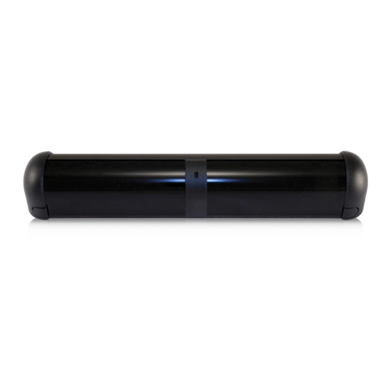
BODYGUARD-T
Presence sensor w/monitoring
2
4
1. End caps
2. Lenses
3. Center eye shield
4. LED
Specifications are subject to change without prior notice.
All values measured in specific conditions.
1
Page 1 of 12
Advertisement
Table of Contents

Related Manuals for BEA BODYGUARD-T


Summary of Contents for BEA BODYGUARD-T
- Page 1 11.8” (L) x 1.9” (H) x 1.9” (W) (305 mm x 51 mm x 46 mm) Material: Aluminum and ABS plastic Housing color: Black, anodized aluminum Specifications are subject to change without prior notice. All values measured in specific conditions. 75.5905.06 BODYGUARD-T 20190402 Page 1 of 12...
-
Page 2: Installation Tips
Sensor must be mounted at center of door opening. Per ANSI 156.10: When the Bodyguard-T is prevented from providing a safety signal to the control during the closing cycle, an additional sensor, sensors, or photo beam shall be used on the swing side to stop the door, or continue to close the door, or slow the reopening. -
Page 3: Mechanical Installation
MECHANICAL INSTALLATION BODYMOUNT INSTALLATION Bodymounts are required for Bodyguard-T installations with one or both of the following circumstances: • reveal (i.e. distance from door face to Bodyguard mounting surface) is less than 3 inches • SuperScan-T is also used Disregard this sub-section and proceed to "Sensor Preparation" if a Bodymount is not required for this application. -
Page 4: Sensor Installation
This detection field may be altered by adjusting would improve the detection field location the angle (see directions below). across the threshold area of the doorway. Page 4 of 12 75.5905.06 BODYGUARD-T 20190402... - Page 5 WIRING TO MODULES If wiring the Bodyguard-T to a BEA module (e.g. LO21, MC15), refer to the respective schematic for the module. Monitoring may not be used if wiring to a BEA module; therefore, the DIP switch must be switched off.
- Page 6 TRY THIS: white wire on lockout OR negative data connection on control brown wire on Bodyguard-T red/white wire on lockout OR positive data connection on control blue wire on Bodyguard-T TRY THIS: check motor voltage (red and black on lockout OR control’s data circuit) has at least 10 VDC...
-
Page 7: Remote Control Setup
Sensor will unlock with one press of UNLOCK key when set to 0000. Sensitivity Hold Time Output Config Auto-Learn Time Pattern Width Pattern Depth Immunity Set-up see next page for specific parameter settings 75.5905.06 BODYGUARD-T 20190402 Page 7 of 12... - Page 8 Be sure to change the setting on BOTH sensors. 3. Change IR frequency on one sensor. 4. If in an application with high-gloss floors or multiple doors installed in vestibules, change to different frequency. Page 8 of 12 75.5905.06 BODYGUARD-T 20190402...
-
Page 9: Push-Button Set-Up
0 – 9 flashes (default = 1) 7 flashes Pattern depth (door open) 1 – 6 flashes (default = 1) 8 flashes Pattern depth (door closed) 1 – 6 flashes (default = 1) 75.5905.06 BODYGUARD-T 20190402 Page 9 of 12... - Page 10 Row 1 (spots 1 – 6) remain on even during the "closed-door" position. 1: DEEP 2: MIDDLE 3: LIMITED 4: DEEP WITHOUT ROW 1 5: MIDDLE WITHOUT ROW 1 6: LIMITED WITHOUT ROW 1 Page 10 of 12 75.5905.06 BODYGUARD-T 20190402...
-
Page 11: Troubleshooting
Verify that there are no breaks anywhere in the wire harness. Door control does not utilize Move monitoring DIP switch to the right (OFF) OR apply 12 – 30 VDC to the monitoring purple and purple/yellow wires (observe polarity). 75.5905.06 BODYGUARD-T 20190402 Page 11 of 12... - Page 12 BEA strongly recommends that installation and service technicians be AAADM-certifi ed for pedestrian doors, IDA-certifi ed for doors/gates, and factory- trained for the type of door/gate system.
Need help?
Do you have a question about the BODYGUARD-T and is the answer not in the manual?
Questions and answers