BEA Eagle HM User Manual
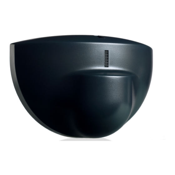
Motion sensor
Hide thumbs
Also See for Eagle HM:
- User manual (8 pages) ,
- Manual (4 pages) ,
- Original instructions (4 pages)
Table of Contents
Advertisement
Quick Links
We open up New Horizons
The High Mounting Eagle Motion Detector (PN: 10EAGLE1HM) nd technology combined with digital processing to assure a
DESCRIPTION
sharp, stable activation pattern with outstanding adjustability. Some of the adjustments include unidirectional sensing
capabilities, 3-dimensional angle adjustment, and heightened immunity to highly sensitive motion settings.
adjustments can be made with BEA's universal remote control. Other accessories available for the Eagle include the false
ceiling adapter (ECA), and the rain protection cover (ERA).
TECHNICAL
SPECIFICATIONS
Terminal Block
DESCRIPTION OF
THE SENSOR
Passage
INSTALLATION
TIPS
75.1038 V2 Aug 2001 [Rev. June 10, 2005]
USERS GUIDE
PRELIMINARY
Frequency:
Supply voltage:
Mounting height:
Tilt angle:
Detection area:
Minimum detection speed:
Power consumption:
Standard output relay:
Max contact voltage
Max contact current
Max switching power
Hold time:
Temperature range:
Dimensions:
Weight:
Material:
Housing color:
Cable length:
Buttons
Wire
Hole
Planar
Antenna
The sensor must be
firmly fastened in order
not to vibrate.
EAGLE HM
MOTION SENSOR
24.125 GHz
12 to 24 V AC : ± 10% :
12 to 24 V DC : -10% / +30% :
16.5 feet
0° to 90° vertical
-30° to +30° lateral
13.1 ft x 8.2 ft
2in/sec. (measured in axis)
< 2 W
60 VDC / 125 VAC
1 A (resistive)
30W (DC) / 60VA (AC)
0.5 sec. to 9 sec. (adjustable)
-4°F to 131°F
4.75in (W) x 3.15in (H) x 2.0in (D)
0.5lbs
ABS
Black. Can be painted with non-metallic paint
30ft
Lateral Adj.
For Antenna
The sensor must not be
placed directly behind a
panel or any kind of
material.
The sensor must not
have any object likely to
move or vibrate in its
sensing field.
These
The sensor must not
have any fluorescent
lighting in its sensing
field.
Page 1 of 8
Advertisement
Table of Contents

Related Manuals for BEA Eagle HM


Summary of Contents for BEA Eagle HM
- Page 1 Some of the adjustments include unidirectional sensing capabilities, 3-dimensional angle adjustment, and heightened immunity to highly sensitive motion settings. adjustments can be made with BEA’s universal remote control. Other accessories available for the Eagle include the false ceiling adapter (ECA), and the rain protection cover (ERA).
- Page 2 SAFETY • Shut off all power going to the header before attempting any wiring procedures. PRECAUTIONS • Maintain a clean & safe environment when working in public areas. • Constantly be aware of pedestrian traffic around the door area. • Always stop pedestrian traffic through the doorway when performing tests that may result in unexpected reactions by the door.
- Page 3 - Example of use with a normal operator. Shown in picture C above. 75.1038 V3 Jun 2005 [Rev. June 10, 2005] The antenna for the Eagle HM is identified by it’s 9 elements. There is no narrow or wide antenna. Only the 9 element antenna is utilized for the Eagle HM.
- Page 4 MECHANICAL ADJUSTMENTS - SETTING THE SENSING FIELD DIMENSIONS – Cont. For ceiling mounting, the vertical tilt angle of the antenna must be set at the maximum position of 70-75° and the spherical part of the sensor must be oriented in the opposite direction to the door.
- Page 5 The Eagle SMR is fully compatible with BEA’s Remote Control as shown below. Use of the remote control should be BEA’s REMOTE conducted within 10’ – 15’ of the sensor, and the remote should be pointed directly at the sensor when used. Refer to the “Programming Guide”...
- Page 6 PROGRAMMING GUIDE Cont. UNLOCK UNLOCKING & LOCKING LOCK CHECK VALUES SENSITIVITY RELAY HOLD TIME RELAY CONFIGURATION 75.1038 V3 Jun 2005 [Rev. June 10, 2005] USER’S ACTIONS Press the UNLOCK key once, then enter your 4-digit code to unlock the Eagle. When all parameters have been set, press the LOCK key once.
- Page 7 PROGRAMMING GUIDE Cont. DETECTION MODE IMMUNITY DEFAULT VALUE If a remote control is not available, you can adjust the sensitivity parameter ONLY, by means of the push MANUAL SET-UP buttons + (Plus) and - (Minus). The sensor parameters that are not accessible manually will remain at the factory preset values. Pressing the two push buttons, located on the circuit board, simultaneously for at least two seconds, will restore all default values.
- Page 8 OTHER ACCESSORIES PN: 10ECA For mounting into the ceiling, use the ECA embedding accessory. If after troubleshooting a problem, a satisfactory solution cannot be achieved, please call B.E.A., Inc. COMPANY for further assistance during Eastern Standard Time at 1-800-523-2462 from 8am - 5pm. CONTACT For after-hours, call East Coast: 1-866-836-1863 or 1-800-407-4545 / Mid-West: 1-888-308-8843 / West Coast: 1-888-419-2564.
Need help?
Do you have a question about the Eagle HM and is the answer not in the manual?
Questions and answers