
Related Manuals for I-PEX CABLINE-CAL PLUG


Summary of Contents for I-PEX CABLINE-CAL PLUG
- Page 1 ASM-17003 Document No. CABLINE -CAL PLUG ® Part No. 20728 Assembly Manual S19443 July 16, 2019 S.Yamaguchi T.Kurachi H.IKari Rev. Date Prepared by Checked by Approved by Confidential C I-PEX Inc. QKE-DFFDE09-04 REV.8 1 / 13...
-
Page 2: Housing Ass'y
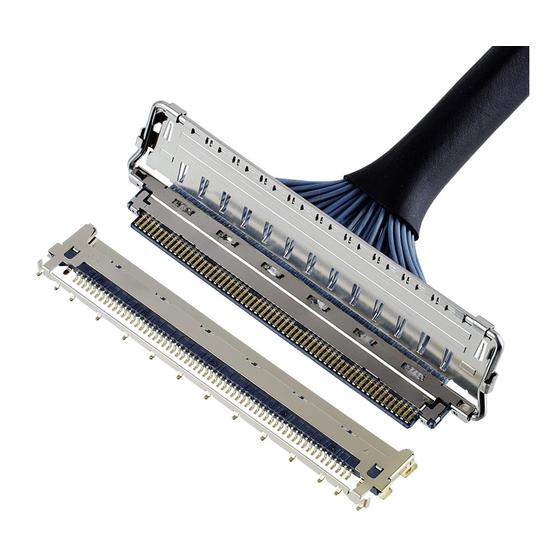
ASM-17003 1. 目的 (Purpose): CABLINE-CAL PLUG における、ケーブルの半田付け手順及び SHELL-A, LOCK BAR の組み付けについて明記する。 This manual is to explain the soldering method / process of the CABLINE-CAL PLUG with cable, and assembly of SHELL-A, LOCK BAR. 2. 適用コネクタ (Applicable connector): Name: CABLINE-CAL PLUG Parts No.:... - Page 3 Document No. CABLINE-CAL Assembly Manual ASM-17003 4. パルスヒート条件[推奨] (Recommended pulse heat condition) Micro-Coax ①アイドリング温度 (Idle temp.) 150℃ ②1 ヒート設定温度 (1 heat temp.) 220℃ ③ 〃 立ち上がり時間 ( 〃 rise time) 0.5sec. ④ 〃 維持時間 ( 〃 holding time) 3.0sec. ⑤2 ヒート設定温度...
- Page 4 Document No. CABLINE-CAL Assembly Manual ASM-17003 5. 作業手順 (Work procedures): 5-1. 芯線の半田付け (Soldering of center-conductor) ①まず適合ケーブルの端末処理形状を下図の様にして下さい。 The cables have to be fabricated as shown below in advance of soldering. RECOMMENDED MICRO-COAX CABLE MICRO-COAX AWG#** Confidential C 4 / 13...
- Page 5 Document No. CABLINE-CAL Assembly Manual ASM-17003 ② ディスペンサー等でコンタクトにフラックスを塗布し、全コンタクトにフラックスが塗布されたことを確認して下さい。 Apply flux to contact by the dispenser etc., and please confirm all contacts were applied flux. Applying Flux area Photo.1 After applying flux ※Photo.2 のようにフラックスを塗布し過ぎないで下さい。 フラックスの飛散及びフラックス過多による嵌合部への染み出しの原因となります。 ※Please do not apply flux too much like Photo.2. It can cause flux splash or leak to the mating area. Photo.2 Extra flux ※洗浄機等によるフラックスの洗浄は行わないで下さい。フラックスが嵌合部に付着する可能性が有ります。...
- Page 6 Document No. CABLINE-CAL Assembly Manual ASM-17003 ③ コネクタに半田バーをセットする。 Pre-set and locate solder bar at center of connector (HSG ASS’Y). Solder Bar Fig.1 Set of solder bar ④ ケーブルをセットする。 Set the cable. ※ディスクリートケーブルのセットは芯線と SHELL が接触する恐れがある為、Fig.3 のように 0.25MAX を守ってください。 ※Setting discrete cable is to protect 0.25MAX. as Fig.3. There is danger that Center Conductor touch SHELL. ※裏表に注意してください。...
- Page 7 Document No. CABLINE-CAL Assembly Manual ASM-17003 ⑤ 芯線をパルスヒートにて半田付けする。 半田付け状態は、下記 Photo.3 参照。 Center-conductors are soldered with pulse heater. See photo.3 of soldering condition. Photo.3 AWG#40 ※万が一、極間が短絡した場合は、再度パルスヒートにて加熱を行って下さい。 製品にダメージを与える恐れがある為、回数は 1 回だけです。 短絡が直らない場合は、NG 箇所のみ半田コテにて手修正して下さい。 ※When solder bridge is appeared between the terminal, try heating again with pulse heater only one time. If the bridge isn’t repaired, use the soldering iron only a NG point.
- Page 8 Document No. CABLINE-CAL Assembly Manual ASM-17003 注意:PLUG HSG ASS'Y の SHELL 底面には、Fig.4 の箇所に凸形状を設けておりますので、 パルスヒート受け JIG には、干渉しないように凸形状の逃がしを設けてください。 Caution: The SHELL bottom side of PLUG HSG ASS'Y has convex shape at the points shown in Fig.4, so please make escape shape on the receiving jig of the pulse heater to prevent interference. 8.80 18.60 12.80...
- Page 9 Document No. CABLINE-CAL Assembly Manual ASM-17003 5-2. SHELL-A 取扱注意事項 (Cautions in treating SHELL-A) SHELL-A はキャリア付きリール状態にて納品されます。SHELL-A をキャリアから折り取る手順を明記します。 SHELL-A is delivered in the reel with a carrier. The following is the method to cut SHELL-A from Carrier. ① キャリアを,金属用はさみ等を用いて下左写真(photo.4)の Cut Line(緑線)にて切断する。 Cut carrier on the cut line of the left below picture (green line) by a scissors for metal. Carrier Cut Line Notch...
- Page 10 Document No. CABLINE-CAL Assembly Manual ASM-17003 注意:下写真(赤矢印)の様に無理やり引っ張ったりして切り離すとバリや変形の原因になります。 Caution: By pulling like the photo below to cut off by force (Red arrow direction), burrs and transformation can be caused. Photo.10 Cut by force (Bad example) 5-3. LOCK BAR 組み付け (Assembly of LOCK BAR) Fig.5 の様に...
- Page 11 Document No. CABLINE-CAL Assembly Manual ASM-17003 5-4. SHELL-A 組み付け (Assembly of SHELL-A) ① Fig.6 の様に SHELL-A を HOUSING ASS’Y の上側から組み付ける。 SHELL-A is assembled from the upper side of HOUSING ASS’Y . Fig.6 Assembly of SHELL-A ② SHELL-A が正常に組み立てられているか確認する。 SHELL どうしのロックが掛かっているか。(Fig.7★部) Confirms whether SHELL-A is assembled properly.
- Page 12 Document No. CABLINE-CAL Assembly Manual ASM-17003 ③ SHELL-B と GND BAR を半田コテにて全箇所半田付けする。 (Fig.8◆部) 半田の高さ(半田量)の限度は Fig.11 参照。 半田コテの条件は、7 頁参照。 SHELL-B and GND BAR are soldered with the soldering iron at all designated points. (Fig.8◆point) Refer to Fig.11 for a limit of the solder height. For conditions of Soldering iron refer to sheet 7.
- Page 13 Document No. CABLINE-CAL Assembly Manual ASM-17003 5-5. ケーブル固定 (Cable fixation) ケーブル端末部を接着剤にて固定する。 接着剤: LOCTITE 352 Fix the cable terminal part with the bond. Bond: LOCTITE 352 Fig.10 Bonding VIEW A VIEW A (半田染み出し/ Solder leaking) Fig.11 Soldering & Bonding Confidential C 13 / 13...
Need help?
Do you have a question about the CABLINE-CAL PLUG and is the answer not in the manual?
Questions and answers