Table of Contents
Advertisement
Quick Links
Advertisement
Table of Contents

Related Manuals for Regulus SRS 3


Summary of Contents for Regulus SRS 3
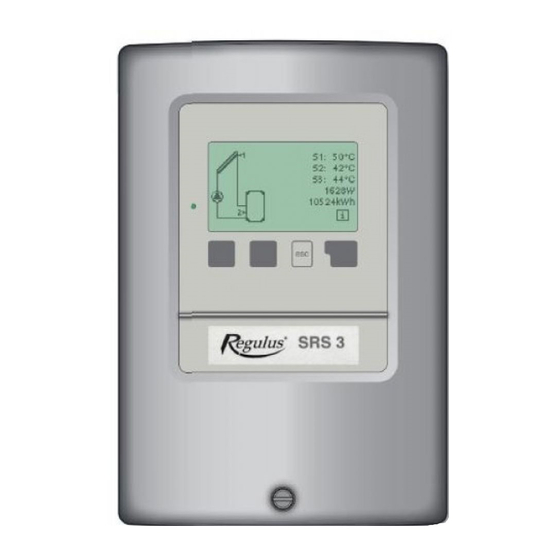
- Page 1 Instruction Manual REGULUS SRS 3 Controller v 1.2...
-
Page 2: Table Of Contents
E 1 - Error and info messages ........................ E 2 - Replacing the fuse .......................... E 3 - Maintenance ........................... E 4 - Useful hints and tricks ........................E 5 - Disposal ............................REGULUS - SRS 3 Controller - www.regulus.eu │... -
Page 3: A 1 - Specification
Pt1000, pipe-mounted sensor TR/P4 up to 95 °C Sensor leads min. 2× 0,75 mm , extendable up to 30m max. Temperature resistance table for Pt1000 sensors: °C Ω 1000 1039 1077 1116 1155 1194 1232 1270 1308 1347 1385 REGULUS - SRS 3 Controller - www.regulus.eu │... -
Page 4: A 2 - About The Controller
A 2 - About the controller The REGULUS SRS 3 controller is designed to control solar systems with 1 solar collector field and up to 2 loads or 1 load and up to 2 solar collector fields. It can be used in solar systems for DHW and pool heating or backup heating. -
Page 5: A 5 - Hydraulic Variants
18. Solar system + zone valve + thermostat 19. One differential ∆T controller and 1 thermostat (no solar functions) 20. 2 temperature difference controllers 2×∆T (no solar functions) (ΔT-Controller) (2xΔT-Controller) Δ 2xΔ REGULUS - SRS 3 Controller - www.regulus.eu │... -
Page 6: A 6 - Wall Installation
7. Fit the upper part of the housing and insert the other two screws. fixing points 8. Align the housing and tighten the three screws. fixing fixing points points Fig. A 3.1.2 REGULUS - SRS 3 Controller - www.regulus.eu │... -
Page 7: A 7 - Electrical Wiring
For solar collectors, use sensors of a suitable temperature resistance (min. 180 °C) that are enclosed in the supply. The temperature sensor cables must be routed separately from mains voltage cables! REGULUS - SRS 3 Controller - www.regulus.eu │... -
Page 8: B 1 - Solar System With Storage Tank
N Mains pump L (speed) 230VAC pump N thermostat function L thermostat function N protective conductor (green-yellow) R1 output: for speed control of standard solar pumps, minimum load 20VA. Caution REGULUS - SRS 3 Controller - www.regulus.eu │... -
Page 9: B 3 - Solar System With By-Pass
R2 off = valve closed = flow direction B-AB = no backup heating R2 on = valve open = flow A-AB through the storage tank R1 output: for speed control of standard pumps, minimum load 20VA. Caution REGULUS - SRS 3 Controller - www.regulus.eu │... -
Page 10: B 5 - Solar System With Thermally Stratified Storage Tank
N Mains pump, secondary L 230VAC pump, secondary N pump, primary L pump, primary N protective conductor (green-yellow) R1 output: for speed control of standard pumps, minimum load 20VA. Caution REGULUS - SRS 3 Controller - www.regulus.eu │... -
Page 11: B 7 - Solar System With 2 Collector Fields (East/West)
230VAC pump (coll. 1) L pump (coll. 1) N pump (coll. 2) L pump (coll. 2) N protective conductor (green-yellow) R1 output: for speed control of standard pumps, minimum load 20VA. Caution REGULUS - SRS 3 Controller - www.regulus.eu │... -
Page 12: B 9 - Solar System With 2 Storage Tanks And Zone Valve
(storage tank 1) L 230VAC pump (storage tank 1) N pump (storage tank 2) L pump (storage tank 2) N protective conductor (green-yellow) R1 output: for speed control of standard pumps, minimum load 20VA. Caution REGULUS - SRS 3 Controller - www.regulus.eu │... -
Page 13: B11 - Solar System With 2 Storage Tanks And Heat Exchange Pump
N pump L (speed) pump N Mains 230VAC pool pump L pool pump N protective conductor (green-yellow) R1 output: for speed control of standard pumps, minimum load 20VA. Caution REGULUS - SRS 3 Controller - www.regulus.eu │... -
Page 14: B13 - Solar System With Pool And Storage Tank
L (speed) pump N cooling L cooling N protective conductor (green-yellow) Description of cooling function - see chapter D 6.4.1 R1 output: for speed control of standard pumps, minimum load 20VA Caution REGULUS - SRS 3 Controller - www.regulus.eu │... -
Page 15: B15 - Solar System + Cooling 2
N cooling pump L cooling pump N protective conductor (green-yellow) Description of cooling function - see chapter D 6.4.1 R1 output: for speed control of standard pumps, minimum load 20VA Caution REGULUS - SRS 3 Controller - www.regulus.eu │... -
Page 16: B17 - Solar System + Solid Fuel Boiler
R2 off = valve closed = flow direction B-AB = backup heating R2 on = valve open = flow direction A-AB = no backup heating R1 output: for speed control of standard pumps, minimum load 20VA Caution REGULUS - SRS 3 Controller - www.regulus.eu │... -
Page 17: B19 - One Temperature Difference Controller 1×∆T And One Thermostat
If temperature S1 > temperature S2, R1 pump relay switches. If temperature S2 > temperature S3, R2 pump relay switches. R1 output: for speed control of standard pumps, minimum load 20VA Caution REGULUS - SRS 3 Controller - www.regulus.eu │... -
Page 18: C 1 - Display And Input
Examples of key functions: temperature sensor increase/decrease values ▼/▲ scroll menu up/down heat exchanger YES/NO confirm/reject Info additional information Back to previous screen warning/error message new information available REGULUS - SRS 3 Controller - www.regulus.eu │... -
Page 19: C 2 - Menu Structure
6. Solar and frost protection, recooling, antiseizing protection 7. Commissioning help, program selection, sensor calibration, clock etc. 8. Against unintentional setting changes 9. For diagnosis in the event of an error 10. Language selection REGULUS - SRS 3 Controller - www.regulus.eu │... -
Page 20: C 3 - Turning On For The First Time
Then switch on automatic mode. Observe the explanations for the individual parameters on the following pages, and check whether further settings are necessary for your application. Caution REGULUS - SRS 3 Controller - www.regulus.eu │... -
Page 21: D 1 - Measurement Values
If the cables are too long or the sensors are not placed optimally, the result may be small deviations in the measurement values. In this case the display values can be compensated for using the function of sensor compensation - see Chapter D 7.3. REGULUS - SRS 3 Controller - www.regulus.eu │... -
Page 22: D 2 - Statistics
Caution Please note that the clock does not continue to run if the mains voltage is interrupted, and must therefore be reset. Incorrect time set in Regulus SRS 3 controller may result in data being deleted, recorded incorrectly or overwritten. -
Page 23: D 3 - Display Mode
No hydraulic system is shown. D 3.3 - Alternating menu 3.3 In alternating mode the diagram mode and then the overview mode are active for 5 seconds at a time. REGULUS - SRS 3 Controller - www.regulus.eu │... -
Page 24: D 4 - Operating Mode
This special operating mode is intended only for the filling procedure for a special „Drain Master System” with a fill level contact. It is not used in Regulus solar systems. However, if you activate it, be sure to terminate the function when finished! -
Page 25: D 5 - Settings
Temperature values which are set too high will allow higher solar heat accumulation but it shall be checked that all system components are resistant to high temperature and scalding protection is provided. Regulus solar systems are safe for heating water up to 95 °C. Danger D 5.5 Tmax S3... - Page 26 If the Energy saving mode is active (see D 5.16), the system heats up until Tmin S3+hysteresis temperature is reached. Setting range: Hysteresis 2 to 20 °C / default setting: 10 °C REGULUS - SRS 3 Controller - www.regulus.eu │...
- Page 27 If Increase > 3 °C/min., Interruption time is extended until the switching condition S1-S2 < ΔT R1 for S2 storage tank is met. If the increase is less than 3 °C/min.…………………………………S3 storage tank is charged REGULUS - SRS 3 Controller - www.regulus.eu │...
- Page 28 - When no solar heat is available, additional heating is switched on when Tset S3 is reached and heats up to Tset S3+hysteresis, i.e. like in normal mode. Additional heating mode. Setting range: ON, OFF / default setting: OFF REGULUS - SRS 3 Controller - www.regulus.eu │...
- Page 29 (on) - 30 °C (off). If no solar heat is available, then the el. heating rod heats the storage tank to 60 °C (on) - 70 °C (off) between 6:00 and 22:00, like in normal mode. REGULUS - SRS 3 Controller - www.regulus.eu │...
- Page 30 REGULUS - SRS 3 Controller - www.regulus.eu │...
-
Page 31: D 6 - Protective Functions
Frost protection stage 2 setting range: from -25 °C to 8 °C or off/default setting: 5 °C This function causes energy loss via the collector! As Regulus solar systems are filled with antifreeze fluid, the antifreeze protection shall remain off. Caution D 6.3 - System protection... - Page 32 LED starts flashing and a warning message is shown in the display. Setting range: Collector alarm off, on / default setting: off Setting range: Col. alarm 60 °C to 300 °C / Default setting: 150 °C REGULUS - SRS 3 Controller - www.regulus.eu │...
- Page 33 This protection is efficient only where a high temperature is present, that is why the Danger circulation pump shall be switched on at the same time, ensuring piping protection as well. REGULUS - SRS 3 Controller - www.regulus.eu │...
-
Page 34: D 7 - Special Functions
All of the settings that have been made can be reset, thus returning the controller to its delivery state. The entire parameterization, analyses, etc. of the controller will be lost irrevocably. The controller must then be commissioned and set once again. Caution REGULUS - SRS 3 Controller - www.regulus.eu │... - Page 35 Purging time setting range: 2-30 sec. / default setting: 5 sec. Increase setting range: 1 °C - 10 °C / default setting: 3 °C / min. In Regulus tube collectors the sensor sheath is placed in optimum position inside the collector and the start help function is not needed.
- Page 36 When the valve is set toward the primary storage, speed control works as in V3 (see above). When the valve is set toward the secondary storage, speed control works as in V2. Setting range: V1, V2, V3, off / default setting: off REGULUS - SRS 3 Controller - www.regulus.eu │...
- Page 37 Wait for another 15 minutes and note down the collector temperature each minute. The time needed for the collector temperature to calm down after the speed change is the min. time to be set as the Sweep time. REGULUS - SRS 3 Controller - www.regulus.eu │...
-
Page 38: D 8 - Menu Lock
To lock the other menus, select „Menu lock on”. To enable the menus again, select „Menu lock off”. Setting range: on, off/default setting: off It is advisable to keep the lock activated in order to prevent unintentional changes by a user. Caution REGULUS - SRS 3 Controller - www.regulus.eu │... -
Page 39: D 9 - Service Values
9.51. 9.22. 9.52. 9.23. 9.53. 9.24. 9.54. 9.25. 9.55. 9.26. 9.56. 9.27. 9.57. 9.28. 9.58. 9.29. 9.59. 9.30. 9.60. Note: ADC1 to 3 are internal data of temperature transducer 1 to 3. REGULUS - SRS 3 Controller - www.regulus.eu │... -
Page 40: D10 - Language
Menu „10. Language” can be used to select the language for the menu guidance. This is queried automatically during initial commissioning. The controller involves English, German, Italian, Polish and Czech language versions. REGULUS - SRS 3 Controller - www.regulus.eu │... -
Page 41: E 1 - Error And Info Messages
Means that the controller was restarted, for example due to a power failure. Check the date&time! Time&date This message appears automatically after a mains failure because the time&date have to be checked, and reset if necessary. REGULUS - SRS 3 Controller - www.regulus.eu │... -
Page 42: E 2 - Replacing The Fuse
- Check the error memory (see D 7.5) - Verify/check plausibility of the current measurement values (see D 6) - Check the switch outputs/consumers in manual mode (see D 9.2) - Poss. optimize the parameter settings REGULUS - SRS 3 Controller - www.regulus.eu │... -
Page 43: E 4 - Useful Hints And Tricks
In the universal programs 19 + 20 the times refer to relay R1. To protect against loss of data, record any analyses and data that are particularly important to you at regular intervals. REGULUS - SRS 3 Controller - www.regulus.eu │... -
Page 44: E 5 - Disposal
WEEE registration number: 02771/07-ECZ disposal service, or the shop where you purchased the product. 04/20 REGULUS spol. s r.o. Do Koutů 1897/3 http://www.regulus.eu 143 00 Praha 4 E-mail: sales@regulus.cz REGULUS - SRS 3 Controller - www.regulus.eu │...
Need help?
Do you have a question about the SRS 3 and is the answer not in the manual?
Questions and answers