Table of Contents
Advertisement
Quick Links
Advertisement
Chapters
Table of Contents

Subscribe to Our Youtube Channel
Related Manuals for Regulus IR 12


Summary of Contents for Regulus IR 12
- Page 1 Users Guide IR 12 Heating Controller Ver.: IR12_KRB ver. 1.9 Valid for FW 4.01...
-
Page 2: Table Of Contents
Technical Description of IR 12 Heating Controller ..............3 1. How to operate IR 12 Controller ..................3 1.1 Basic User Menu ......................4 2. User menu ......................... 8 2.1 Heating zones ......................9 2.2 Setting temperatures for hot water storage tank ............10 2.3 DHW recirculation .......................11... -
Page 3: Technical Description Of Ir 12 Heating Controller
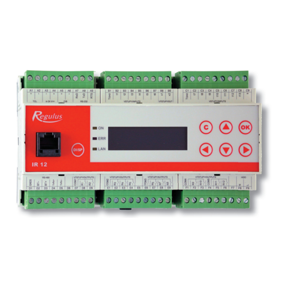
IR 12 Heating Controller is controlled by 6 keys. Information is shown on a 4-line display. The Controller features 13 inputs for temperatures measured (by Pt 1000 temperature sensors) and one input for Ripple control signal. -
Page 4: Basic User Menu
The keys , are used to browse in the menu. In order to edit a parameter, press OK and a cursor appears on the parameter. The values of numeric parameters can be increased/decreased by pressing / keys. Selection parameters (e.g. ON/OFF) are chosen by pressing keys , . - Page 5 3 – current room temperature. If no room sensor is used, the real temperature is shown as 0°C. Temperature for zone 1 only. 4 – desired room temperature. 5 – adjustment to the desired room temperature. When RC21 IR room unit is used, “PJ“ appears and the adjustment made by this unit is shown.
- Page 6 Solar thermal system display: 1 – solar collector temperature 2 – system ON 3 – ON = solar pump running 4 – currently charged tank mark 5 – desired temp. for tanks when charged from solar 6 – current temp. in tanks 7 –...
- Page 7 3 – desired flow temperature 4 – current flow temperature Return heating water valve display: 1 – state of return water valve (absent – return water valve is not present; mixing – return water to boiler is mixed from return heating water and preheated water in Thermal Store; toBoil – return heating water is diverted directly into boiler;...
-
Page 8: User Menu
UNI module universal module extending both inputs and outputs – absent/active (shows whether the module is connected to PLC controller) output state of the module’s universal output (a function adjustable on the service level) t1, t2 temperatures at temperature sensors of the module Service Menu is intended for more detailed adjustments to zones, sources, solar thermal system and other parameters. -
Page 9: Heating Zones
User menu is comprised of: • zone 1 • zone 2 • DHW zone • DHW recircul. • time program (time programs) • OTC Curves • operation data (temperatures and outputs condition) • time, date • other (adjusting other parameters) •... -
Page 10: Setting Temperatures For Hot Water Storage Tank
setback setting heating water temperature reduction calculated from the OTC curve when the mode changes from comfort to setback as preset by the time schedule. The Winter/Summer function is active if the zone is in Auto mode. The Controller will set the zone temperatures by the parameters set. -
Page 11: Dhw Recirculation
T setback setback temperature. Hot water storage tank gets heated up to this temperature if the program is set to “Setback“ at the moment. T from ThS hot water storage tank is heated to this temperature (at DHWL sensor) from this function disregarded of time schedules and comfort/setback temperatures selected. -
Page 12: Time Programs
schedule defines from-to operation times. For this period, circulation time and idle time can be set if continuous operation is not desired. E.g. Monday from 6.00 a.m. to 10.30 p.m. the recirculation pump will always run for 10 min. and then idle for 15 min. on (off / on) recirculation switched on. -
Page 13: Otc Curves
Holidays: Temperature control of separate zones following a special time schedule. Temperatures in zones can be set, as well as the date and time for the beginning and end of the time program. zone 1 desired temperature in zone 1. zone 2 desired temperature in zone 2. -
Page 14: Operation Data
OTC points settings: Point I1 represents the highest temperature that can be calculated by the controller, while point I4 represents the lowest temperature that can be calculated. 2.6 Operation data All temperature inputs and logical output values of the controller are displayed here. The logical value of 0 means a valve closed, pump not running;... -
Page 15: Setting Other Parameters
Having set time and date, press and the following display appears: When this display is shown, time and date are being saved into the real-time circuit of the controller. 2.8 Setting other parameters website password reset Selecting yes will reset the website password and username to the default username: user and password: user. -
Page 16: Setting Sms
2.9 Setting SMS This function can be accessed only in combination with a GSM modem and its description can be found in its specific Manual. 2.10 Heat and energy measurement This display offers information on the momentary heat output (in Kw), on the total heat supplied (in kWh) and information on the current flow rate (in m3/h) and on total volume flown through (in liters). -
Page 17: Web Interface
3. Web interface 3.1 Introduction The controller contains integrated web pages displaying an overview of the heating system and user settings. In order to get access to the web pages of the controller, it shall be connected either to a LAN or directly to a PC through a crossover network cable. -
Page 18: Functions Adjustable From A Web Browser
3.2 Functions Adjustable from a Web Browser All parameters accessible in the menu on the controller’s display can be adjusted via the web browser. The web environment further enables adjustment of parameters that are accessible from the browser only. These involve password change, synchronization settings, adjusting and displaying weather forecast, e-mail notifications, displaying charts and some selected statistics. - Page 19 IR12_KRB FW 4.01 S 1 – Controller wiring ......................20 S 1.1 – Technical parameters of IR 12 controller ..............20 S 1.2 - Technical parameters for OpenTherm™ module IR 1x OT ........21 S 1.3 – Controller installation ....................22 S 2 – Service menu ......................23 S 2.1 –...
-
Page 20: S 1 - Controller Wiring
1 valve closes sensor 1 (RC) zone 1 Ripple Control N outside Ripple Control L flow meter S 1.1 – Technical parameters of IR 12 controller Power supply Power supply voltage 24 V DC ± 5% Power input 9.6 W max. Installation... -
Page 21: S 1.2 - Technical Parameters For Opentherm™ Module Ir 1X Ot
R1,R2 Outputs COM terminal max. current 2 A Relay current 1 A (230 V AC) Relay type semi-conductor R3-R12 Outputs COM terminal max. current 10 A Relay current 3 A (12-230 V AC) Relay type electromechanical 0-10V Output Output voltage 0-10V DC Common wire Max. -
Page 22: S 1.3 - Controller Installation
S 1.3 – Controller installation The Controller is designed for installation on a DIN rail in a fuse board. It may be installed by authorized staff only! The controller, power supply unit and optional OpenTherm communication module shall be installed close to each other (cf. the interconnection fig.). Prior to turning the Controller on, the ADR rotation knob shall be pointed to “0”. -
Page 23: S 2 - Service Menu
S 2 – Service menu Warning: This Service Menu may be edited by qualified staff only. Improper parameter setting in the Service menu may cause damage to system components in both heating and solar circuits. In order to enter Service Menu, select “service“ in the User Menu and press OK. Password to enter Service menu: Pressing OK will move from one password digit to the next. -
Page 24: S 2.1 - Heating Zones Setting (1,2)
uni. output universal output 1 (controller universal terminal) uni. output 2 universal output 2 (controller second universal terminal) switching on SMS function (adjustable from user interface) heat settings for heat and flowrate measurements statistics statistics for some parameters control type control type choice (mixed zone 1/heating return valve) test controller outputs test... - Page 25 an extra option (fromZ1) and in such a case the data from RC21 unit wired to zone 1 are valid for zone 2. no room sens.recalc. DTheat./room (°C) Temperature drop setting between heating water and room temperature. E.g. the value 3 means that a desired change in room temperature by 1°C needs a heating water temperature change by some 3°C.
- Page 26 Mixing valve: shift time (sec) Setting the shift time between end positions of the mixing valve. manual gain If the preset value is not acceptable and the control shall be slowed down/speeded up, the switch shall be turned to yes. Then the following item, gain, can be changed.
-
Page 27: S 2.2 - Solar Zone Service Parameters Setting
block if ThSt temp. lower than zone min. temperat. (yes/no) Blocks the zone when ThSt temperature (ThSt upper sensor) is lower than min. heating water temperature. Prevents extensive cooling of the thermal store. S 2.2 – Solar Zone Service Parameters Setting Solar system may work with one, two or three hot water storage tanks. - Page 28 dif. on (°C) Difference to switch on solar circuit. Difference between solar collector and temperature sensor set in parameter sensor. dif. off (°C) Difference to switch off solar circuit. demand t. (°C) The desired temperature. Under the normal solar circuit mode, the tank is heated up to this temperature.
- Page 29 condition of switching difference is met – cf. more details in the description of Oscillating loading function. idle time (min) Time period the Controller idles, waiting if the solar collector temperature rises. The description see parameter t. increase. sol.tank 2(3) (min) If a tank of higher priority cannot be loaded, a tank of lower priority is loaded for the time period set in this parameter.
-
Page 30: S 2.3 - Dhw Zone Service Parameters Setting
If the temperature in tank X is higher than that set in parameter Max. temp. tank X (e.g. due to collector cooling), tank X will get cooled via the collector. Cooling shall start if the collector is cooler by at least 6°C than tank X. Tank number (X) is set in parameter nmbr. of solar tank for collect. -
Page 31: S 2.4 -Opentherm Source Service Parameters Setting
diff. on (°C) Setting the difference between Thermal Store and DHW tank that controls starting the DHW pump. diff. off (°C) Setting the difference between Thermal Store and DHW tank that controls stopping the DHW pump. RC (yes/no) Option if DHW tank loading is blocked from RC signal. sens.DHW (sensor list) Choice of sensor in DHW tank for the function of DHW via Thermal Store. - Page 32 However the source might run and keep circulation pump running for some time which is caused by safety algorithms of the source that cannot be overridden by the Controller. max. t. out. (°C) Setting the max. flow temperature from an OpenTherm source. This value will be sent to the source to limit its max.
-
Page 33: S 2.5 - On/Off Source Service Parameters Setting
shift time (sec) Setting of mixing valve shift time from one end position to the other one. manual gain If the preset value is not acceptable and the control shall be slowed down/speeded up, the switch shall be turned to yes. Then the following item, gain, can be changed. -
Page 34: S 2.6 - Nastavení Servisních Parametrů Modulovaného (0-10 V) Zdroje
diff. on (°C) Setting the difference between boiler return temperature and that demanded by a heating system, for source 2 to be switched on. diff. off (°C) Setting the difference between boiler return temperature and that demanded by a heating system, for source 2 to be switched off. delay (min) Setting the delay in boiler start after the demand based on temperature difference appeared. - Page 35 selected, the 0-10V output signal is in direct relationship to the desired temperature. Ripple c. (yes/no) Settings for 0-10V source control by Ripple control signal. sensor (sensor list) Control sensor for a 0-10V source. max. temp. (°C) Setting of max. flow temperature from a heat source. This temperature will be used as the upper limit value for a desired boiler temperature.
-
Page 36: S 2.7 - Fireplace Service Parameters Setting
Parameter settings for the output signal of temp. type (see the first adjustment screen). min. temp. (°C) Min. temperature, corresponding to signal min. parameter. max. temp. (°C) Max. temperature, corresponding to signal max. parameter. This is just to set the output signal level which does not need to correspond to the max. -
Page 37: S 2.8 - Other Service Parameters
fireplace temp. to start pump (°C) Setting the temperature of water outgoing from fireplace above which the fireplace circulation pump starts. max. Thermal Store temp (°C) The max. Thermal Store temperature for the fireplace function. When this temperature is exceeded, the fire pump is turned off. - Page 38 state (active/off) Turning frost protection on/off. out. temp. (°C) Setting outdoor temperature limit below which Frost protection is activated. water temp. (°C) Heating water temperature kept in a zone when Frost protection is active. Critical temperature in Thermal Store: If the temperature in Thermal Store exceeds the set critical temperature, cooling will start with heating into all zones switched on in Service level, i.e.
-
Page 39: S 2.9 - Temperature Sensor Management (15 Screens For 15 Temperature Sensors)
S 2.9 – Temperature Sensor Management The temperature measured by the Controller may differ from a real temperature due to defects. The measured value may be affected e.g. by the preciseness of the temperature sensor, the length and cross section of the cable used for sensors, by the quality of contact between the temperature sensor and the medium measured. - Page 40 The following displays enable adjusting the function of universal thermostat (uni1 thermostat or uni2 thermostat). sens 1,2 Temperature sensor selection for universal thermostat functions. For control type 2 the heating return sensor is replaced by the flow sensor in zone 1!!! The universal thermostat features the following functions: •...
- Page 41 on/off (on/off) Switching thermostat 1 function on/off. t. on (°C) Switch-on temperature for thermostat 1. t. off (°C) Switch-off temperature for thermostat 1. If the switch-on temperature is higher than the switch-off temperature, thermostat 1 works in a “cooling” mode, if vice versa, it works in a “heating” mode. request for boiler from Thermostat 1/2 (on/off) Switch-off temperature for Thermostat 1/2 will be taken over as the desired temperature for heat sources.
- Page 42 on/off (on/off) Switching the delay function on/off. period (minutes) Delay time in case when all the preceding functions are fulfilled. Overrun: overrun function (output delayed switch-off) on/off (on/off) Switching the overrun function on/off. overrun (minutes) Overrun time after the preceding functions are switched off. Timer: timer functions with two time periods on/off (on/off)
-
Page 43: S 2.11 - Sms Setting
S 2.11 – Universal outputs 0-10V uni1, uni2 Assign universal analogue outputs, options are: output is not used fire damper damper on the fireplace combustion air inlet is assigned DHW circ.p. DHW recirculation pump (switched) is assigned to this output src. - Page 44 flowrate (m3/h) If no pulse flowmeter is present, the flowrate value shall be entered manually. inlet Inlet temperature sensor for the purpose of heat measurements (select). For control type 2 the heating return sensor is replaced by the flow sensor in zone 1!!! outlet Outlet temperature sensor for the purpose of heat measurements (select).
-
Page 45: S 2.13 - Total Statistics
reset heat (Yes/No) Measured heat values are reset (all statistics, from hourly to total values). reset flow (Yes/No) Measured values of flow rate and fluid volume passed through are reset (all statistics, from hourly to total values). S 2.14 – Total statistics Statistics of sources and all pumps operation and of solar tanks heating, in HH:MM format. -
Page 46: S 2.15 - Output Test
S 2.16 – Output test When Output test in Service Menu is entered, all outputs from the Controller are switched off. Then separate outputs can be tested. The output turns on when a display with the name of the output in question is shown and the option test = 1 selected. On leaving a display with the option test = 1, the respective output switches off. - Page 47 thermostat, diff. thermostat and delay functions. The Timer function is superior over the preceding functions. Description of separate functions and parameters of the add-on module module (on/off) Add-on module switching on (entering the right HW address is a precondition for its proper operation – see 2.16). sens 1, 2 Temperature sensors for thermostat functions (thermostat 1, 2 and differential thermostat)
- Page 48 Thermostat 1/2 is set in Heating mode. When Timer function is also On, the request will be taken over during active time period only. Differential thermostat: differential thermostat function between sensors 1 and 2 on/off (on/off) Switching differential thermostat function on/off. diff.
-
Page 49: S 2.17 - Hw Address Setting For Cib Modules
on/off (on/off) Switching the timer function on/off. on 1 (hh:mm) The first period switch-on time. off 1 (hh:mm) The first period switch-off time. on 2 (hh:mm) The second period switch-on time. off 2 (hh:mm) The second period switch-off time. reset state of T1 T2 with every start of the period of the program When this function is On, at every start of time period in time program the state of both thermostats will be reset according to the current temperature. -
Page 50: S 2.18 - Ip Addresses
MAC (00.00.00.00.00.00) MAC address of the Controller. S 2.20 – RegulusRoute RegulusRoute service enables remote access to the Controller avoiding the need to use a public IP address. If you wish to have this service configured, kindly contact Regulus. - Page 51 RegulusRoute (yes/no) Enabling RegulusRoute service. status Service state.
-
Page 52: S 3 - Web Server - Service Level
S 3 – Web Server – service level IR12 Controller is equipped with integrated web server that enables displaying either User or Service screen S 3.1 - Access to Service web interface, checking the IP address of the Controller In order to access the Controller’s interface via web browser, you need to know its IP address. -
Page 53: S 4 - Rc21 Ir Room Unit, Wiring
Room unit in Zone 1: Unit terminal 1 → IR12 terminal C6 (t11) (sensor 1) Unit terminal 2 → IR 12 terminal C7 (t12) (Zone 1) Unit terminal 3 → IR 12 terminals B1,C1 (T The RC21 sensor type needs to be enabled on the Service level. - Page 56 WARRANTY CERTIFICATE IR 12 Heating Controller Seller: ..........Date of Purchase: ........WARRANTY CONDITIONS The warranty period is 24 months from the date of purchase. The product shall be installed and commissioned by a competent company or a person trained by the manufacturer.
Need help?
Do you have a question about the IR 12 and is the answer not in the manual?
Questions and answers