
Subscribe to Our Youtube Channel
Related Manuals for Regulus SRS2 TE


Summary of Contents for Regulus SRS2 TE
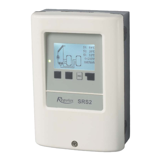
- Page 1 Installation, Wiring and Operating Instructions REGULUS SRS2 TE Solar Controller v. 1.3...
-
Page 2: Table Of Contents
CONTENTS 5.2. - System protection EC Declaration of Conformity 5.3. - Collector protection General information 5.4. - Recooling Explanation of symbols 5.5. - Frost protection Changes to the unit 5.6. - Seizing protection 5.7. - Collector alarm Specifi cation Temperature resistance table for 6. - Page 3 This Instruction Manual applies to the following hardware version: SRS2 TE 2 output mechanical relays 460 W 1 output mechanical relays 3.5 kW 3 inputs for Pt1000 temperature sensors...
-
Page 4: Ec Declaration Of Conformity
Safety Instructions EC Declaration of Conformity The manufacturer declares that the SRS2 TE Solar Controller is marked with the CE mark and conforms to the following relevant safety regulations: - Directive 2014/35/EU - EU low voltage directive - Directive 2014/30/EU - EU electromagnetic compatibility directive... -
Page 5: Changes To The Unit
Safety Instructions Changes to the unit • Changes, additions to or conversion of the unit are not permitted without a written permission from the Manufacturer. • It is forbidden to install any additional components into the controller that has not been tested together with the controller. -
Page 6: Specifi Cation
IP rating IP40 El. protection class Overvoltage category Pollution degree SRS2 TE Mechanical relay, 460 VA (AC1), 460 W (AC3) 2 (R1, R2) Mechanical relay, 3500 VA (AC2), 3500 W (AC3) 1(R3) Pt1000 sensors, from -40 °C to +300 °C... -
Page 7: Description
SRS2 TE Controller is designed for automatic control of solar thermal systems. The SRS2 TE model is intended to control solar thermal systems with one solar array and one solar consumer. The solar consumer can be a hot water storage tank, a heat ex- changer for a swimming pool, and a thermal store for heating. -
Page 8: Hydraulic Variants
Description Hydraulic variants 1. Solar with hot water storage tank 2. Solar with hot water storage tank and el. heating element 3. Solar with hot water storage tank and gas boiler 4. Solar with hot water storage tank and heat pump 5. -
Page 9: Wall Installation
Installation Wall installation Install the controller in dry areas only. Warning Installation instructions:: 1. Unscrew cover screw completely. C.1.1 2. Carefully pull the upper part of the hou- sing from the lower part. 3. Set the upper part of the housing aside, being sure not to touch the electronics when doing so. -
Page 10: Electrical Wiring
Installation Electrical wiring Before working on the unit, switch off the power supply and secure it against being switched on again! Check for the absence of power! Electric wiring may only be done by a specialist in compliance with valid Danger rules. -
Page 11: Installing The Temperature Sensors
Installation C 2. 1 Wiring instructions: C.2.1 Select the necessary hydraulic variant (B.6). 2. Open the controller as described in C.1 3. Strip the cable by 55 mm max., insert and fit the cable strain relief. Strip the last 8-9 mm of all the wires (Fig. C.2.1) 4. -
Page 12: Terminal Block Wiring
Installation D.1 - Terminal block wiring CAN CAN Extra low voltage Mains voltage max. 12 V 230 V Danger Warning Extra low voltage max. 12 V Mains voltage 230 V 50 Hz Terminal: connection for: Terminal: connection for: sensor 1 neutral N sensor 2 relay 1... -
Page 13: Example Of El. Heating Element Wiring
Installation D.2 Example of el. heating element wiring Controller SRS2 TE sensor 4 mains voltage 230 V el. heating element L - mains phase N - mains neutral PE - protective conductor... -
Page 14: Display And Input
Operation Display and input The display (1) shows graphic and text info on the hydraulic variant, set and measured values and other text info. LED lamp (2): lights up green - if a relay is closed and the controller works right lights up red - if the controller is set to automatic operation and all relays are open... -
Page 15: Commissioning Help
Operation Commissioning help The fi rst time the controller is turned on, language and clock need to be set. After that a query appears as to whether you want to parameterize the controller using the Setup Wizard or not. The setup wizard can also be terminated or called up again at any time in the special functions menu. -
Page 16: Menu Sequence And Menu Structure
Operation Menu structure The graphics or overview mode appears when no key has been pressed for 2 minutes, or when the main menu is exited by pressing “esc“. Pressing any key (4) in graphics or overview mode takes you directly to the main menu. -
Page 17: Measurements
Measurement values 1. - Measurements Menu “1. Measurements” serves to dis- play the currently measured temperatures. What measurement values are displayed depends on the selected program and the specific controller model. The menu is closed by pressing “esc” or selecting “Exit measurements”. If “--”... -
Page 18: Statistics
Statistics 2. - Statistics Menu “2. Statistics” is used for function control and long-term monitoring of the system. The menu is closed by pressing “esc” or selecting “Exit statistics”. For analysis of the system data it is essential that time is set accurately on the controller. -
Page 19: Operating Modes
Operating modes 3. - Operating modes In menu “3. Operating modes” the cont- roller can either be switched to automatic mode, turned off, or placed in a manual operating mode. The menu is closed by pressing “esc” or selecting “Exit operating mode”. 3.1. -
Page 20: Settings
Settings 4. - Settings The system parameters are set in menu “4. Settings”. The menu is closed by pressing “esc” or selecting “Exit settings”. 4.1. - Tmin S(X) Sensor S(X) switch-on temperature If the temperature at sensor S(X) exceeds the value of TminS(X) and the other con- ditions are also met, then the controller switches on the associated pump and/or valve. -
Page 21: Tmax S(X)
Temperature values which are set high will allow higher solar heat accu- mulation but it shall be checked that all system components are resis- Danger tant to high temperatures and scalding protection is provided. Regulus solar thermal systems are safe for heating water up to 95 °C. -
Page 22: Auxiliary Heat Source
Settings 4.14. - Auxiliary heating Auxiliary heat function based on time or temperature. 4.14.1. - TH Set Target temperature at thermostat sensor 1. Below this temperature, auxiliary heating is switched on, till TH set + hysteresis is reached. Setting range: 0°C to 100 °C / Default setting: 50°C Temperature values which are set too high can lead to scalding or dam- age to the system. -
Page 23: Periods
Settings 4.14.7. - Periods Set the desired periods of time when the thermostat should be active. 2 periods can be set per day, settings can also be copied to other days. Outside the set times the auxiliary heat source is switched off. Setting range: from 00:00 to 23:59 / Default setting: 06:00 to 22:00 4.15. -
Page 24: Protective Functions
Protective functions 5. - Protective functions Menu “5. Protections” can be used to acti- vate and set various protective functions. This does not under any circumstances replace the safety facilities to be provided by the Warning customer! The menu is closed by pressing “esc” or selecting “Exit protections“. -
Page 25: System Protection
Protective functions Protective functions This anti-Legionella function does not provide complete protection against Legionella, because the controller is dependent on sufficient energy being fed in, and it is not possible to monitor the temperatures in the entire range of the storage tanks and the connected piping system. To provide Warning complete protection against Legionella bacteria, it must be ensured that the temperature is raised to the necessary temperature, and at the same... -
Page 26: Frost Protection
Setting range: Frost level 2 -25 to 8 °C or OFF / Default setting: 5 °C This function causes energy loss via the collector! As Regulus solar thermal systems are filled with antifreeze fluid, the antifreeze protection shall remain off. -
Page 27: Special Functions
Special functions 6. - Special functions Menu “6. Special functions” is used to set basic items and expanded functions. Time and Date is the only function to be set by the user. Other functions may be set by a Warning specialist only. -
Page 28: Output Signal
Special functions 6.2.3. - Output Signal This menu determines the type of pump used: Solar pumps perform at their highest power when the signal is also at its maximum, heating pump on the other hand are set to highest power when the control signal is at its minimum. Solar = Normal, Heating pumps = Inverted. -
Page 29: Speed Control R1
Special functions 6.3. - Speed control R1 6.4. - Řízení otáček 6.3.1. - Varianty řízení otáček R1 6.3.1. - Modes R1 6.3. - Řízení otáček 6.2.3. - Varianty řízení otáček R1 Off: There is no speed control. The connected pump is only switched on or off with full speed. -
Page 30: Max.speed
Special functions 6.3.4. - Max.speed 6.9.1. - Max. otáčky The maximum speed of the pump is specified here. Setting range: 15-100% /Default setting: 100% The indicated percentages are guide values that may vary to a greater or lesser extent depending on the system, pump and pump stage. Caution 6.3.5. -
Page 31: Glycol Percentage
Special functions 6.7.6. – Glycol percentage Concentration of antifreeze used in the system, in %. Setting range: 0 % - 60 % / Default setting: 40 % 6.7.7. - Flow rate This determines the fl ow rate in litres per minute that is used for the calcualtion of the heat quantity. Setting range: 0 l/min. -
Page 32: Start Aid Function
Special functions The entire parameterization, analyses, etc. of the controller will be lost irrevocably. The controller must then be commissioned and set once again. Caution 6.11. - Starting aid function With some solar thermal systems, namely with evacuated tube collectors, it may occur that measurement at the collector sensor takes too long or is not quite precise, which is often caused by the sensor not being placed at the hottest location. -
Page 33: Menu Lock
Menu lock 7. - Menu lock Menu “7. Menu lock” can be used to secure the controller against unintentional changing of the set values. The menu is closed by pressing “esc” or selecting ”Exit menu lock”. The menus listed below remain completely accessible despite the menu lock being activated, and can be used to make adjustments if necessary: 1. -
Page 34: Service Values
Service values 8. - Service values The menu “9. Service values” can be used for remote diagnosis by a specialist in the event of an error etc. Note down data at the time when an alarm or error occurs, e.g. into the following table. -
Page 35: Language
Language 9. - Language Menu “9. Language” can be used to select the language for the menu guidance. This is queried automatically during initial commissioning. -
Page 36: Malfunctions With Error Messages
Malfunctions Malfunctions with error messages If the controller detects a malfunction, the red light flashes and the warning symbol also appears in the display. If the error (LED fl ashes + is no longer present, the warning symbol warning symbol) changes to an info symbol and the red light no longer flashes. -
Page 37: Replacing The Fuse
Malfunctions Replacing the fuse Repairs and maintenance may only be performed by a specialist. Before working on the unit, switch off the power supply and secure it against Danger being switched on again! Check for the absence of power! Only use the supplied spare fuse or a fuse of the same design with the following specifications: T2A 250V. -
Page 38: Useful Hints And Tricks
Useful hints and tricks Instead of setting the flow rate for the system using a flow rate limiter, it is better to adjust the flow rate using the switch on the pump and by means of the “Max. speed” setting on the controller (see 6.3.4.Max. speed). This saves electricity! The service values (see 8) include not only current measurement values and operating states, but also all of the settings for the controller. - Page 40 04/2017 REGULUS spol. s r.o. Do Koutů 1897/3 http://www.regulus.eu 143 00 Praha 4 E-mail: sales@regulus.eu CZECH REPUBLIC...
Need help?
Do you have a question about the SRS2 TE and is the answer not in the manual?
Questions and answers