
Related Manuals for Regulus uREG


Summary of Contents for Regulus uREG
- Page 1 NIVERSAL ONTROLLER & P ROTECTION ELAY USER MANUAL REGULUS, P 2011-2018 OZNAŃ Version 1.14_ENG...
- Page 2 User Manual LogCZIP® and uREG® are registered trademarks of REGULUS Zygmunt Liszyński.
- Page 3 - is trained in OH&S and first aid. CAUTION The documentation of the uREG relay contains necessary instructions relating to installation, start-up and operation of the equipment. However, it is not possible to mention all essential circumstances or detailed information regarding all probable concepts in this particular document. In case of any doubt or specific problem, please refrain from any action until an authorized confirmation is obtained.
- Page 4 User Manual...
- Page 5 User Manual DECLARATION OF CONFORMITY Manufacturer: REGULUS Zygmunt Liszyński, ul. Bonin 20/28, 60-658 Poznań, ul. Piątkowska 122/9 – 10, 60-649 Poznań, Poland hereby declares that ® uREG Universal Bay Controller and Protection Device: has been designed and manufactured in conformance with essential requirements...
-
Page 6: Table Of Contents
INTRODUCTION & INTENDED USE ..........................9 SCOPE OF THE MANUAL ............................9 FUNCTIONS AND FEATURES ........................... 10 TECHNICAL DATA ..............................14 INSTALLATION DATA............................... 19 DESIGN AND STRUCTURE OF THE uREG SYSTEM ....................24 6.1. HARDWARE ................................24 6.2. SOFTWARE STRUCTURE ............................27 uREG HARDWARE MODULES .......................... - Page 7 MEASUREMENTS ..............................74 13.1. SECONDARY MEASUREMENTS ..........................76 13.2. PRIMARY MEASUREMENTS .............................78 EVENT RECORDER – REPORTS ..........................81 14.1. REPORTS – PREVIEW THOUGH uREG MENU ......................81 14.2. REPORTS – PREVIEW THOUGH THE APPLICATION SOFTWARE ................83 14.3. SYSTEM REPORTS ..............................84 DATA RECORDERS ..............................86 15.1.
- Page 8 User Manual GUIDELINES FOR THE PURCHASER ........................107 WARRANTY ................................107...
-
Page 9: Introduction & Intended Use
User Manual 1. INTRODUCTION & INTENDED USE uREG® is a universal Intelligent Electronic Device (IED) providing fault protection, measurements, control, communication, logging, to be operated together with automation solutions installed in MV and HV power system substations. uREG is based on many years of experience gained by its designers during development,... -
Page 10: Functions And Features
User Manual 3. FUNCTIONS AND FEATURES (depending on the developed APPLICATION) The most important features: Short-circuit overcurrent fault protection (ANSI 50/51) from effects of line-to-line short-circuit fault with an independent single-stage characteristic curve. For the short time after operational power-up of a bay, current and time settings can be dynamically modified by adjustable increments to shift the tripping shutdown point. - Page 11 User Manual Distributed busbar protection in incoming feeders and busbar protection interlock in outgoing feeders (activated if current setting IZS>> is exceeded). Closing interlocks for any selectable criteria. Distributed multistage smart load (SCO) and load restoration (Reclose the circuit breaker after tripping ANSI 79 - SPZ/SCO) automation and/or two-stage SCO automation, centralized with SPZ/SCO.
- Page 12 User Manual Conventional remote control (telemechanics) by wired circuits for receiving/transmitting signals (via terminal inputs/outputs) as an alternative to communication channels. Operation of substations switchgear with SF6 and enclosed switchgears (support of relief vents). Measurements of true RMS values for 12 analog voltage and current signals, power coefficient tgor cos...
- Page 13 User Manual Access to change settings via operator panel keyboard, secured by a two-level user code (two buttons pressed in a defined sequence). Changing settings via PC requires no password. The manufacturer recommends changing settings via PC since this approach is simple.
-
Page 14: Technical Data
User Manual 4. TECHNICAL DATA Phase current input circuits Rated current In 5 A or 1A Measurement range 0 ÷ 192 A Measurement error within ranges: 0.05 ÷ 0.35 A <5 % 0.35 ÷ 50 A <1.5 % 50 ÷ 192 A <5 %... - Page 15 User Manual Dependent overcurrent protection Activity and mode of the dependent criterion RI > inactive, OW Overcurrent-stage starting current I> 0.3...50 A Time delay of 2-fold overcurrent tI> 0.05...24 s Slope of the dependent characteristic curve wtI > moderate,...
- Page 16 User Manual Line-to-earth short-circuit fault protection Starting current of Io> 50 ÷ 5000 mA Internal start-up time for 2-fold value of exceeded setting 20 ÷ 50 ms (typical 35 ms) Adjustable resetting ratio 0.910 ÷ 0.985 Admittance non directional protective functions Y0>, G0>...
- Page 17 User Manual Signaling relay output circuits Rated voltage 220 V DC Continuous current-carrying capacity Inductive circuit breaking: 220 V DC, L/R= 40 ms 0.1 A Rated voltage 250 V AC Continuous current-carrying capacity 220 V AC, cos =0.4 Breaking capacity:...
- Page 18 User Manual Immunity to external interference Interfering signal 2.5 kV/1 MHz/400 ud/s Environmental conditions Ambient temperature C...+55 Storage temperature C...+70 Atmospheric pressure >800 hPa Relative humidity <75% - no condensation or frost and ice formation inside case Housing High-grade steel (A4), acid-proof...
-
Page 19: Installation Data
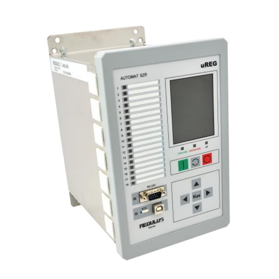
User Manual 5. INSTALLATION DATA For panel flush installation (7-slot enclosure). Mechanical installation for the integrated panel version. Drilling diagram. - Page 20 User Manual Panel flush (#2) version. Mechanical installation for the remote panel version. Drilling diagram for the panel. Drilling diagram for 7-slot enclosure installation.
- Page 21 User Manual Drilling diagram for 10-slot enclosure installation.
- Page 22 User Manual Drilling diagram for 14-slot enclosure installation.
- Page 23 User Manual For panel surface installation (7-slot enclosure). Mechanical installation for the integrated panel version. Drilling diagram. REMARKS: 1. Prior to fastening the panel to the enclosure with an integrated panel, drive in UNC4-40 screws into DB9M sockets in the panel.
-
Page 24: Design And Structure Of The Ureg System
User Manual 6. DESIGN AND STRUCTURE OF THE uREG SYSTEM uREG system is modular. The modular design applies both to electronic hardware, used to assemble a specific device, but also to its enclosure and functional software. The device software has separate layers which carry out distinctly distinguished tasks. - Page 25 Fig. 6.1.3. The 10-slot enclosure viewed on the side of module terminals (enclosure mounted behind the panel). The decision on numbers and types of applied modules is made by the user, depending on expected protective function to be provided by uREG. However, the minimum configuration must include: ...
- Page 26 User Manual External terminal connectors and communication connectors (IF-x module) are accessible at the back of the enclosure. A detailed description of the modules is provided in section 7. uREG can be equipped with one of three operator panels: ...
-
Page 27: Software Structure
The user is still able to update BASE. top layer (the so-called APPLICATION) – is a structure consisting of logic conditions to decide on the purpose and protective functions provided by uREG. LogCZIP APPLICATION layer is defined by the manufacturer or user via utility software. -
Page 28: Ureg Hardware Modules
User Manual 7. uREG HARDWARE MODULES uREG system modules have standard external dimensions: 142.0 x 90.0 mm (width x height). The modules are installed in respective slots on the motherboard (MB). Slot arrangement and sizes (IDC type) on the motherboard (MB) determine corresponding slots for the modules, which prevents making an error. -
Page 29: If-4 Module (Slot 0)
Modbus TCP, Compatible with IEC-61850. The IF-x module is required to start up uREG. The IF-4 module is a functional equivalent of IF-0, equipped with 2 x CAN-BUS interfaces. The IF-3 module – functional equivalent of IF-4, out of production. -
Page 30: If-2 Module (Slot 0)
User Manual 7.2. IF-1 / IF-2 MODULE (SLOT 0) Versions of the IF-0 module equipped with fiber optic (FO – fiber optic) connectors (IF-1: one Tx-Rx pair or IF-2: two pairs) instead of copper RS-485 and AUX-485 interfaces. Two fiber types are allowed: ... -
Page 31: Module (Slot 1)
User Manual 7.4. CT-0 MODULE (SLOT 1) In the CT-0 module (current transformers module), there are 3 current transformers for direct measurements of phase currents within the range (In: 5 A, 1 A) = 0 ÷ 192 A. Phase current input circuits... -
Page 32: Module (Slot 1)
User Manual 7.5. VP-0 MODULE (SLOT 1) VP-0 – module in the third voltage section, e.g. ATS units. Terminals of the VP-0 module are grouped into three Wieland-Wiecon 4-pin symmetric ports (screwed, type 8313S/4 WF OB; pitch: 7.50 mm, max continuous capacity 12 A, 400 V, cable cross-section 2.5 mm2). -
Page 33: Vt-5 Module (Slot 2)
User Manual 7.6. VT-0 / VT-5 MODULE (SLOT 2) The VT-0 module houses 4 measuring voltage transformers for U0, U1, U2, U3 and 2 current transformers for I0 and Ig. The module additionally has 3 unipolar digital inputs (AUXI 0..2), which can be also used for analogue measurements (sensitivity threshold selectable by setting). -
Page 34: Vt-1 Module (Slot 2)
User Manual 7.7. VT-2 / VT-1 MODULE (SLOT 2) The VT-2 module with double voltage transformers is mainly designed for supporting ATS automatic units and wind plants. The VT-2 module houses 2 sets of 4 measuring transformers for voltages U0, U1, U2, U3 and 1 current transformer for I0. -
Page 35: Vt-4 / Vt-8 Module (Slot #2)
User Manual 7.8. VT-3 / VT-4 / VT-8 MODULE (SLOT #2) The VT-3 module with double voltage transformers is mainly designed for supporting automation solutions at wind plants. The VT-3 module houses 2 sets of 4 measuring transformers for voltages U1, U2, U3 and 3 current transformer for If. -
Page 36: Module (Slot #2)
User Manual 7.9. VT-6 MODULE (SLOT #2) VT-6 – voltage transformers module, transformers of the second current section + Ig, I0. Under development. 7.10. VT-7 MODULE (SLOT #2) The module has three voltage transformers for U1, U2, U3 within the range 5 ÷ 260 V (optionally 500 V AC) and two full If stars. -
Page 37: Ps -0/ Ss-0 Module (Slots 3 & 6)
User Manual 7.11. PS -0/ SS-0 MODULE (SLOTS 3 & 6) The PS-0 power supply module is a switching power unit module dedicated to uREG. uREG Each unit can be equipped with one or two PS-0 module(s) (installed in slot #3 and/or #6). -
Page 38: Module (Slots 3 & 6)
The SS-0 module is a functional equivalent to the PS-0 module; it has no switching-mode power unit. 7.12. PS -1 MODULE (SLOTS 3 & 6) The PS-1 is a 24 V DC switching power unit module dedicated to uREG. Rated supply voltage: 24 V DC Admissible range of supply voltage changes: 21 ÷... -
Page 39: Module (Slots 3 To 13
User Manual 7.13. CR-0 MODULE (SLOTS 3 to 13…) The CR-0 module (controlled by a dedicated Cortex controller) is an universal I/O module with a power relay, equipped with: 2 x SR6-51 power relays → terminals 22, 2 internal inputs for power relay control;... -
Page 40: Module (Slots 3 To 13
User Manual 7.14. CM-0 MODULE (SLOTS 3 to 13…) CM-0 is analogous to CR-0; it features a less advanced configuration: 2 x SR6-51 power relays → terminals 22, 2 internal inputs for power relay control; 1+1+4+5 = 11 digital inputs with programmable sensitivity threshold >20/>50 V DC... -
Page 41: Module (Slots 3 To 13
User Manual 7.15. CO-0 MODULE (SLOTS 3 to 13…) The CO-0 module is a smart module with 16 identical relay outputs (for signaling). Fig. 7.15. Terminals of the CO-0 module. 7.16. CI-0 MODULE (SLOTS 3 to 13…) CI-0 is a smart module with 16 digital inputs and 1 relay output (for signaling), with the following topology: ... -
Page 42: Module (Slots 3 To 13
Features of the GP-0 module: - module form a wide range of uREG modules, installed in the protection slot (also supplied by the slot); - SIM slot, push-push type (easy access to SIM); - communications ports: 2 x RS-485, USB;... - Page 43 - GP-0/x/z – single or two-channel, external enclosure (supply: 12 V DC). Fig. 7.18.1. Sockets of the GP-0 module. Rys.7.18.2. uREG with the GP-0 module installed. Full specification of the GP-0 module together with a presentation brochure are provided in a separate...
-
Page 44: Fixed Hardware Configurations
CT-0 VT-0 PS-x CR-0 CR-0 CI-0 uREG-37 IF-x CT-0 VT-2 PS-x CR-0 CM-0 CR-0 CM-0 CM-0 CI-0 … uREG-50 IF-x VT-0 PS-x uREG-51 IF-x CT-0 VT-0 PS-x uREG-52 IF-x VT-4 PS-x uREG-53 IF-x VT-4 PS-x CM-0 Table 7.1. uREG configurations... -
Page 45: Operator Panel - Front Panel
User Manual 8. OPERATOR PANEL – FRONT PANEL uREG According to section 6.1. Hardware, can be equipped with one of 3 operator panels: GH panel – color graphic LCD in TFT QVGA standard, in horizontal arrangement; Fig. 8.1. View of the GH front panel. - Page 46 CAUTION: The operator panel is an accessory, i.e. if there is no panel or it experiences a malfunction, operation of uREG and its protective criteria to be executed will not be affected! Do NOT connect more than one panel to one uREG device!
-
Page 47: Common Features Of The Panels
– circuit-breaker closed. CAUTION: LEDs cannot be programmed via panel on the uREG device. In order to define the response, the APPLICATION layer must be accessed via LogCZIP . The procedure can have two outcomes: 1. LED association with a specific event (fixed association);... -
Page 48: Keyboard
User Manual 8.3. KEYBOARD Meanings and functions of panel buttons result from the description implemented in the APPLICATION. For typical cases and standard APPLICATIONS, the keyboard is used to navigate through screens and the protection menu, including the action of previewing and establishing settings. The keyboard has eight monostable buttons. - Page 49 User Manual The selection is presented by the yellow frame displayed around the switch symbol. Pressing SEL changes cyclically the selection to the next circuit-breaker or disconnector. Shifting the selection to the bay disconnector is conditioned by unambiguous confirmation of the circuit- breaker tripping.
-
Page 50: Lcd Screen
User Manual 8.4. LCD SCREEN 8.4.1. MONOCHROMATIC ALPHANUMERIC DISPLAY An alphanumeric LCD screen in the NV panel presents texts in two rows, 16 characters per row. The display has a wide angle of view and high contrast as designed with STN standard The contrast value can be adjusted to fit the user’s preferences and changing ambient temperature. -
Page 51: Texts
User Manual 8.4.3. TEXTS Texts shown on the display are divided into types indicating the kind of the presented information. The texts are divided into: notification – all texts assigned to the information structure and alarm texts, acknowledgement texts – there are three levels of importance – low, moderate and high. -
Page 52: Communication Link
This program is used for quick, transparent and direct access to information in the uREG unit via RS-232 and/or USB. The program offers simple use of its functions (in particular, as regards setting programming), preview of events (reports), indications, measurements, counters, logger, etc. -
Page 53: Ureg Application Software
User Manual 9. uREG APPLICATION SOFTWARE uREG Brand new controllers are provided by the manufacturer with complete control software (accordingly to requirements stated in the purchase order) so that the device can be quickly installed and put into service (→ APPLICATION). -
Page 54: Editing The Logczip Application
User Manual LogCZIP 9.1. EDITING THE APPLICATION Any application (project) is described using one or many program sheet(s). The number of sheets to be used is unlimited and has no logic meaning. Dividing the project into sheets (and their corresponding number) is associated with maintaining project readability, not formal requirements. - Page 55 User Manual FUNCTIONAL BLOCK Fig. 9.1. Example functor Some functors are equipped with one or more variable parameter(s) to modify computation in the functional block. These parameters given as settings are accessible in the utility software – Monitor3; the values can be changed as the application is evaluated.
- Page 56 User Manual Readability of the application project can be essentially improved by adding texts (→ comments). Comments do not have any logic meaning; they can be added in any place in the sheet and in any order. They usually supplement the information provided by label names of relations and functors.
- Page 57 User Manual Functors of analogue inputs [acc. to configuration of modules], in particular: overcurrent criterion I> tripped overcurrent criterion I>T overcurrent criterion I0> differential fault protection dI> current criterion of computed zero sequence L0>...
- Page 58 User Manual level-controlled RS flip-flop (non-volatile) level-controlled SR flip-flop Q-edge controlled RS flip-flop Q-edge controlled SR flip-flop QQ*-edge controlled SR flip-flop Edge-controlled D flip-flop Edge-controlled D flip-flop with reset volatile SR flip-flop, released by positive edge with Q OR-AND output ...
- Page 59 User Manual Automatic control No • Automatic control Yes BREAKER open • BREAKER closed ON active • ON inactive Functors of audible alarms [1]: Buzzer Functors of digital inputs [acc. to configuration of modules]: ...
-
Page 60: Project Compilation
For the immediate mode, the programmer is called by clicking the integrated circuit upload icon /Narzędzia → Programowanie uREG/. 9.3. - Page 61 User Manual states can be imposed completely asynchronously relative to the application evaluation process. The state of evaluation and computation progress is visualized on the PC monitor in dedicated windows and the project sheet. The most important aspect here is to ensure direct representation (in program sheets) of activation states on functor outputs using square markers drawn on the output lines.
-
Page 62: Ureg Dynamic Debugger
User Manual 9.4. uREG DYNAMIC DEBUGGER The dynamic debugger is used to monitor the current state of the application under any LogCZIP condition. This sub-system is a component of the utility software, called from the tab /Debugger → Debugger Online/. -
Page 63: Ureg Start-Up
(GH, GV), the following test image (example) will be displayed for a while: Fig. 10.1. Test pattern on the display The panel equipped with a NV alphanumeric display will show: * uREG panel * REGULUS – Poznań 10.1. BOOT mode... - Page 64 buttons on the operator panel during auxiliary power -up on uREG ! In BOOT mode, it is possible for uREG to operate together with the Monitor3 program to modify auxiliary settings (relating to transmission and LCD). In BOOT mode, a test pattern will be continuously displayed on GH and GV...
-
Page 65: Application Mode
LCD. CAUTION: uREG will be ready for operation provided that verification of hardware configuration (compatibility of modules in slots with the application project) is successful and suitable for the currently active APPLICATION or more advanced in terms of the project. - Page 66 User Manual For applications supplied by REGULUS, in case inconsistent digital logic states on one of the switches or the circuit-breaker are identified, a relevant text will be displayed on the LCD screen. This may be a piece of information as follows: ! Sprzeczne syg- nały stanu z: WL...
-
Page 67: Menu
User Manual MENU uREG allows the user to make decisions on several useful information, which create the so- called menu. The structure and navigation through menu is similar to those in CZIP i CZIP-1,2,3,4 – menu resembles a structure of an inverted tree. - Page 68 User Manual uREG For the device equipped with a graphic display, pressing Kas shifts to presentation the mimic diagram (main screen). uREG is much easier if external software is used (→ see Monitor3), which can run on Operating OS Windows (recommended XP, 7 or higher).
- Page 69 User Manual Current time yy:mm:dd:hh:mm:ss 1300 Changing time: correct year Correct year rr 1310 Changing time: correct month Month mm 1320 Changing time: correct day Day dd 1330 Changing time: correct hour Hour hh 1340 Changing time: correct minutes...
- Page 70 500..509 Measurements of system parameters Continued list → see Internal measurements LED test Activate LED test Serial number Serial number and uREG version Number Nrr nnnubbapm Project signature Active uREG application signature Signature ssssssssssssssss Reports Event reports Event reports presented in yellow...
-
Page 71: Keyboard Operations
User Manual KEYBOARD OPERATIONS This chapter should familiarize the user with the rules relating to keyboard operations based on examples with the password required to access settings, how to set astronomical time and change display settings. 12.1. PASSWORD Security rules require that access to most settings should be protected with a 2-level password. -
Page 72: Date And Time Settings
User Manual 12.2. DATE AND TIME SETTINGS Changing time settings requires auxiliary voltage power-up. This example shows how to change date from 2000.01.01 to 2011.06.27, and time from 00.00.00 to 18.15.00. 1 Main settings 10 LCD... -
Page 73: Display Settings
User Manual 12.3. DISPLAY SETTINGS Display parameters are accessible in the sub-group ‘10 LCD screen’ where auxiliary settings are provided. They are associated with the LCD screen to adapt it to the user’s preferences. The group ‘7 LCD history’ provides previewing previous texts. -
Page 74: Measurements
User Manual MEASUREMENTS uREG unit has been designed for two purposes: the primary aim to provide protective functions and, additionally, to take electrical measurements during operation of a substation bay. Provision of both objectives requires regular basic measurements of bay electrical uREG parameters. - Page 75 User Manual In order to facilitate operational duties at the protective device, and for easier testing and metrological evaluation of the device, source values and computation sections relating derivative values, are presented externally on two different scales: as secondary values expressed in units of monitored signals across device terminals (identified in the menu by the digit 3), ...
-
Page 76: Secondary Measurements
User Manual 13.1. SECONDARY MEASUREMENTS Table 13.1. Secondary measurements Description Explanation and range Notes 30 Current IL1 Phase current RMS value, 31 Current IL2 range: 0 – 192 [A] 32 Current IL3 33 Ifmax The maximum value out of RMS phase Signals TZ, ZW or KZ just before current in IL1, IL2, IL3 –... - Page 77 User Manual 3R Voltage U12 2 Line-to-line voltage U12 in section 2 [VT-2] 3S Voltage U23 2 Line-to-line voltage U23 in section 2 [VT-2] 3T Voltage U31 2 Line-to-line voltage U31 in section 2 [VT-2] 3U Voltage U110 2...
-
Page 78: Primary Measurements
User Manual 13.2. PRIMARY MEASUREMENTS Table 13.2. Primary measurements Description Explanation and range Notes 40 Current IL1 Phase current RMS value. 41 Current IL2 Range: 0 – (lower value out of: 192*thetaIf, 42 Current IL3 10000) [A] 43 Current Ifmax The maximum value of phase current RMS values in L1, L2, L3 –... - Page 79 User Manual 4S Ecz+ Zone 3 for the direction of energy sourced from Stored active energy sourced from busbars in time 4T Ecz– Zone 0 busbars (Ecz–), no backward state. zones. 4U Ecz– Zone 1 Range: 0 – 10 000 [MWh] 4W Ecz–...
- Page 80 User Manual 4x Voltage U110 2 Voltage U110 in section 2 [VT-2] 4y Voltage U110 1 Voltage U110 in section 2 [VT-1] 4z Voltage U0 1 Voltage U0 in section 1 [VT-2] 4* Voltage UL1 1 Phase voltage UL1 in section 1 [VT-2]...
-
Page 81: Event Recorder - Reports
Previewing recorded reports is possible by means of keyboard operations using the local LCD screen or remotely via readout commands sent from the computer. 14.1. REPORTS – PREVIEW THOUGH uREG MENU The reports are accessible on the main level [ident 6 ‘Reports’] in the menu structure of the LCD screen. - Page 82 User Manual For units equipped with a color GH/GV graphic display, viewing event reports has three options: 1. Three last (earliest) reports are always presented on the main screen, whereas the last report is always highlighted, e.g.: Fig. 14.1. Reports on the main screen of graphic panels.
-
Page 83: Reports - Preview Though The Application Software
User Manual 14.2. REPORTS – PREVIEW THOUGH THE APPLICATION SOFTWARE uREG Monitor3 is supplied with – a PC program – to provide a quick and convenient access to reports, together with their full interpretation (resulting from the defined device APPLICATION). -
Page 84: System Reports
User Manual 14.3. SYSTEM REPORTS uREG system has a special group of reports – System reports – whose code (index) is = 0, identified by a DEC or HEX marker. These reports cannot be redefined by the user (at the... - Page 85 User Manual Backlight will be resumed automatically when the display is cooled down. … … Reserved Failed +5V → Motherboard (MB) supply below +4.75 V Failed +5V → Motherboard (MB) supply exceeds +5.25 V Failed +3.3V → Motherboard (MB) supply below +3.20 V Failed +3.3V →...
-
Page 86: Data Recorders
User Manual DATA RECORDERS 15.1. DAR - Digital and Analog Recorder uREG units are equipped with an additional current / voltage / digital data recorder located in the IF-x module (also referred to as the disturbance recorder), which is associated with selected events affecting protective decisions. - Page 87 User Manual 16*10.24 s, 32*5.12 s. In addition, the IF-4 module combined with the MB-2 or MB-3 motherboard provides a data recorder operated at 3200 Hz (64 samples per period) and recording of up to 192 digital states.
-
Page 88: Cdar - Criterial Rms Recorder
User Manual The nature of OFF and non-OFF events results from the description developed in the APPLICATION. Thus, these may include: trip-out by protection (also by operational protection), trip-out by LRW, functional switching (ZW, KZ, TZ), ... -
Page 89: Communication
User Manual COMMUNICATION uREG units are equipped with a full set of the most common communication interfaces, i.e.: accessible in the link panel: (see → 8. Operator panel) RS 232 serial (acc. to definitions of EIA RS-232C), ... -
Page 90: Interface
User Manual 16.1.1. RS-232 INTERFACE Information interchange via RS 232 (EIA RS-232C) uses a 5-line link with a subset of signal for direct operation together with a PC, modem, or alternatively, another supervisory system. RS 232 interface lines are arranged in a DB9M connector (male): ... -
Page 91: Usb Interface (B-Type)
User Manual 16.1.2. USB INTERFACE (B-type) The Universal Serial Bus (USB) provides communication with an external PC (e.g. laptop/notebook) using a standard cable with A-type pins (from the PC side) and B-type pins uREG (from the side). Fig. 16.1.2. Wiring diagram of USB interface. -
Page 92: Aux-485 Interfaces
User Manual 16.1.3. RS-485 /AUX-485 INTERFACES All RS-485 communication interfaces of the device with an IF-0 module manufactured as a 4-wire link as standard. Thus, each interface can exchange data in full-duplex. RS-485 interface lines are arranged in a DB9F connector (female) as follows: ... -
Page 93: Interface (Panel)
User Manual 16.1.4. PN-485 INTERFACE (PANEL) uREG As already mentioned, the operator panel in can be operated remotely → connected to the central unit by a cable with a length up to 15 m. Communication involves a separated RS-485 interface which is symmetrically reproduced on three side of the IF-x module (installation options →... -
Page 94: Ethernet (Eth) Interface
User Manual 16.1.5. ETHERNET (ETH) INTERFACE uREG is equipped with an insulated Ethernet 10/100BASE-T interface with a standard 8P8C (i.e. RJ-45) port, which has two LEDs to indicate link and activity of the interface. Additionally, port activity is signaled by icon on GH/GV graphic panels. - Page 95 User Manual For standard versions of the device, MAC address is fixed at factory to prepare the device for use within private local networks. If necessary to connect the device to the public network, REGULUS it is recommended to contact technical staff at...
-
Page 96: Communication Settings
Settings no. 25 to 32 refer to panel interface (PN -485) and are reserved (Administrator mode). CAUTION: Changing the settings of: Ethernet port, protocol for 485/FO interface, BTS setting to achieve [Port DISABLED] requires their activation, and uREG must be restarted! - Page 97 User Manual Table 16.2.1. Communication settings (UART communication) Setting designation and description Denomination Setting value IDENT in menu 110 Active active, inactive RS232 activity signal signal used to signal interface activity by the LED (on the panel) RS232 111 Baud speed...
- Page 98 User Manual 11F Activity active, inactive AUX485 activity signal: signal used to signal interface activity by the LED (when ON and on the AX485 panel) 11G Baud speed 300, 600, 1200, Baud speed for AUX485/FO2: for AX485 2400, 4800,...
- Page 99 Reserved setting 12I IEEE 1588 slave, master IEEE 1588 PTP Mode during synchronization of clock by IEEE 1588 protocol, In Master option, one of uREG units become the synchronizer. interlock inactive BTS, BTS interlock for TCP: for TCP active BTS,...
-
Page 100: Tests And Evaluation Of Performance
User Manual TESTS AND EVALUATION OF PERFORMANCE 17.1. TEST CLASSIFICATION uREG contains circuits and software for evaluating its performance and maintaining its readiness for operation. Test equipment and procedures are divided into five categories: Initial performance test (when started): POST procedures (power on self test - initial performance testing) inspect local and peripheral hardware. -
Page 101: Measured Internal Parameters
User Manual 17.2. MEASURED INTERNAL PARAMETERS Some measurements and results of ancillary test procedures can be read out by the operator. These values are accessible through the menu information structure in the group ‘5 Tests’, in the sub-group ‘50 Internal parameters’. -
Page 102: Serial Number
User Manual 17.3.2. SERIAL NUMBER uREG Serial number (ident 52) assigned to has the following format: N15 001uB4 0L ► uREG in BOOT mode N15 001u04x0L ► uREG in APPLICATION mode ------------ |||| ------ |||MB software version [A..Z] (presented in BOOT mode and APPLICATION mode) prod. -
Page 103: Fault Troubleshooting
User Manual FAULT TROUBLESHOOTING Unit faults can be generally divided into three classes: 1. abrupt faults caused by irreversible damage to one or more component(s), which prevents further operation of the device, 2. parametric faults caused by ageing or partial wear of components – gradual deterioration of device quality, 3. - Page 104 User Manual values of attenuation/gain coefficients for most measurements taking place in the controller. For example, the value of the measured current ‘Iw’ is determined by the relationship: Iw = Ip * (1 + p * 0.000122), where ‘Ip’ is the measurement value before calibration.
-
Page 105: Performance And Internal Testing
User Manual PERFORMANCE AND INTERNAL TESTING This section presents suggested instructions for laboratory and operational tests in the MV uREG substation to determine performance. These instructions are universal and relate to most hardware configurations and types of functional applications. -
Page 106: Storage / Prior To Operation
User Manual STORAGE / PRIOR TO OPERATION uREG features a sophisticated design and requires fulfillment of specific conditions during storage. The packaging guarantees protection from external factors which may result in damage. Therefore, DO NOT unpack the device during storage. - Page 107 User Manual GUIDELINES FOR THE PURCHASER The purchase order shall specify: 1. Type of functional APPLICATION and number, e.g.: wind plant 0E6, power plant 1E7, etc. (application type 0/1 specifies hardware configuration, the number 6/7 indicates the application version).
Need help?
Do you have a question about the uREG and is the answer not in the manual?
Questions and answers