
Subscribe to Our Youtube Channel
Related Manuals for Regulus SRS1 T


Summary of Contents for Regulus SRS1 T
- Page 1 Installation and Operation Manual REGULUS SRS1 T Solar Controller SRS1 T...
-
Page 2: Table Of Contents
CONTENTS A. - Safety Instructions 6. - Circ. hysteresis (variant EC Declaration of Conformity 6.1. - Seizing protection General information 6.2. - Frost protection Explanation of symbols 6.3. - System protection Changes to the unit 6.4. - Collector protection Warranty 6.5. - Page 3 This Instruction Manual applies to the following hardware versions: SRS1 T SRS1 T 1 output mechanical relay 230VAC 1 PWM/0-10V output for high-efficiency pumps 3 inputs for Pt1000 temperature sensors...
-
Page 4: Safety Instructions
Safety Instructions EC Declaration of Conformity The manufacturer declares that the SRS1 T Solar Controller is marked with the CE mark and conforms to the following relevant safety regulations: - Directive 2014/35/EU - EC low voltage directive (LVD) - Directive 2014/30/EU - EC electromagnetic compatibility directive (EMC) -
Page 5: Changes To The Unit
Safety Instructions Changes to the unit • Changes, additions to or conversion of the unit are not permitted without a written permission from the Manufacturer. • It is forbidden to install any additional components into the controller that has not been tested together with the controller. -
Page 6: Description
IP rating IP40 El. protection class Overvoltage category Pollution degree SRS1 T Mechanical relay, 3000 VA (AC1), 3000 W (AC3) 1 (R1) 0-10V output, 10% tolerance, 10 kΩ, or PWM output, 1kHz, 10V 1 (V1) Pt1000 sensors, from -40 °C to +300 °C... -
Page 7: Description
Description Description SRS1 T Controller is designed for automatic control of solar thermal systems. The SRS1 T model is intended to control solar thermal systems with up to 2 solar arrays and one or two heat consumers. The heat consumer can be a hot water storage tank, a heat exchanger for a swimming pool, and a thermal store for heating. -
Page 8: Installation
Installation Wall installation Install the controller in dry areas only. Warning Installation instructions: C.1.1 1. Unscrew cover screw completely. 2. Carefully pull the upper part of the housing from the lower part, see C.1.1. 3. Set the upper part of the housing aside, being sure not to touch the electronics when doing so. -
Page 9: Electrical Wiring
Installation Electrical wiring Before working on the unit, switch off the power supply and secure it against being switched on again! Check for the absence of power! Electric wiring may only be done by a specialist in compliance with valid Danger rules. -
Page 10: Installing The Temperature Sensors
Installation C 2. 1 Wiring instructions: C.2.1 1. Select the necessary hydraulic variant (D.1 - hydraulic variants). 2. Open the controller as described in chapter C1. 3. Strip the cable by 55 mm max., insert and fit the cable strain relief. Strip the last 8-9 mm of all the wires (Fig. -
Page 11: Terminal Block Wiring
MAINS SENSORS Installation 100-240 VAC D. - Terminal block wiring Mains voltage Sensor connection 230V – max. 12V Danger Warning - Vi R1 R S1 S1 S2 S2 S3 S3 V - Vi MAINS SENSORS 100-240 VAC - Vi R1 R S1 S1 S2S2S3S3 V - Vi POWER SUPPLY SENSORS... -
Page 12: Hydraulic Variants
Installation SRS1 T Hydraulic variants Hydraulická zapojení The following illustrations should be viewed only as schematic diagrams showing the respective hydraulic variants, do not claim to be complete. The controller does not replace safety device under any circumstances. Depending on the specific application, additional system components... -
Page 13: Operation
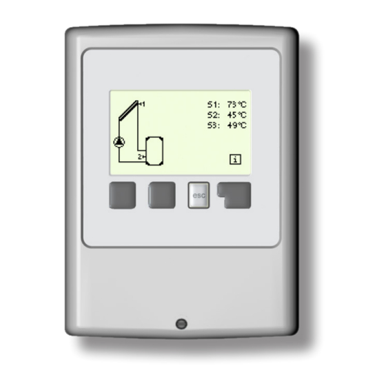
Operation Display and input The display (1) shows graphic and text info on the hydraulic variant, set and measured values and other text info. The LED lamp (2): lights up green - if a relay is closed and the controller works right lights up red - if the controller is set to automatic operation and all relays are open flashes slowly red - if manual operation... -
Page 14: Commissioning Help
Operation Commissioning help - setup wizard The first time the controller is turned on, language and clock need to be set. After that a query appears as to whether you want to parameterize the controller using the Setup Wizard or not. -
Page 15: Menu Sequence And Menu Structure
Operation Menu sequence and menu structure The graphics or overview mode appears when no key has been pressed for 2 minutes, or when the main menu is exited by pressing “esc“. In the graphics menu the display shows (from the top right corner downwards) temperatures at connected sensors, then the current speed of a PWM controlled solar pump, and the current flow rate in the bottom right corner, calculated from the incoming PWM signal (if the incoming PWM signal from the pump is connected). -
Page 16: Measurements
Measurements 1. - Measurements Menu „1. Measurements” serves to display the currently measured temperatures. What measurement values are displayed depends on the selected program and the specific controller model. The menu is closed by pressing „esc” or selecting „Exit measurements”. If “--”... -
Page 17: Statistics
Statistics 2. - Statistics Menu „2. Statistics” is used for function control and long-term monitoring of the system. The menu is closed by pressing „esc” or selecting „Exit statistics”. For analysis of the system data it is essential that time is set accurately on the controller. -
Page 18: Display Mode
Display mode 3. - Display mode Menu “3. Display mode” is used to define the controller’s display for normal operation. This display appears whenever two minutes go by without any key being pressed. The main menu appears again when a key is pressed. -
Page 19: Operating Mode
This can lead, for example, to overheating on the solar collector or other system components. The measured temperatures are Warning displayed even when the controller is Off. 4.4. - Fill system This is not used for Regulus solar thermal systems. -
Page 20: Settings
Temperature values which are set rather high will allow higher solar heat accumulation but it shall be checked that all system components are resistant to high temperature and scalding protection is provided. Regulus Danger solar systems are safe for heating water up to 95 °C. -
Page 21: Tref On / Tref Off (For Variants 1 And 2)
Settings 5.11 – Tref On / Tref Off (for variants 4 and 3) If the temperature at the sensor S3 drops below “Tref On” and the thermostat function is on, the relay for an auxiliary heating will switch on and remain on until the tempera- ture reaches “Tref Off”. -
Page 22: Seizing Protection
If the collector temperature then exceeds the value “Frost level 2” by 2 °C, then the pump switches off again. This function causes energy loss via the collector! As Regulus solar thermal systems are filled with antifreeze fluid, the antifreeze protection shall remain off. Caution 6.3. -
Page 23: Collector Protection
Protective functions Protections 6.4 - Collector protection If „CProt Ton” is exceeded at the collector sensor, the pump is switched on in order to cool the collector down. The pump turns off when the collector temperature drops below „CProt Toff” or the temperature “Cprot Tmax storage” is exceeded in the storage or pool. When this function is active, a storage tank or swimming pool may get heated up to “Storage maximum”, over Tmax S2 (see 5.4. -
Page 24: Al Heat
Protective functions Funkce ochrany 6.7.4 – AL heat This displays the date and time of the last successful heat up. 6.7.5 – AL times During this periods the AL heat up is attempted. This anti-Legionella function does not provide complete protection against Legionella, because the controller is dependent on sufficient energy being fed in, and it is not possible to monitor the temperatures in Caution... -
Page 25: Special Functions
Special functions 7. - Special functions Menu “6. Special functions” is used to set basic items and expanded functions. Time and Date is the only function to be set by the user. Other functions may be set by a specialist only. Warning The menu is closed by pressing “esc”... -
Page 26: Output Signal
Special functions 7.2.3. - Output Signal This menu determines the type of pump used: Solar pumps perform at their highest power when the signal is also at its maximum. Heating pump on the other hand are set to highest power when the control signal is at the lowest. Solar pump = normal, Hea- ting pump = inverted. -
Page 27: Speed Control
Special functions 7.3. - Speed control SRS1 T enables changing the speed of connected pumps using this function. This function should only be activated by a specialist. Depending on the pump used and its performance, the minimum speed should not be set too low, because otherwise the pump or the system may be damaged. -
Page 28: Purging Time
Special functions 7.3.2. - Purging time During this time period, the pump is running with full speed (100%) to ensure trouble-free startup. After this time has passed, the pump is set to speed control and is set to max. speed or min speed, depending on the speed control mode (M1-M3) chosen. 7.3.3. -
Page 29: Time & Date
Special functions 7.4. - Time & date This menu is used to set the current time and date. For analysis of the system data it is essential for the time to be set accurately on the controller. Caution 7.5. - Sensor calibration Deviations in the temperature values displayed, for example due to cables which are too long or sensors which are not positioned optimally, can be compensated for manually here. -
Page 30: Starting Aid
Special functions 7.9. - Starting aid With some solar thermal systems, especially with vacuum tube collectors, it may occur that the measurement value acquisition at the collector sensor occurs too slowly or too inaccurately because the sensor is often not at the hottest location. When the start help is activated the following sequence is carried out: If the temperature at the collector sensor increases by the value specified under “Increase”... -
Page 31: Menu Lock
Menu lock 8. - Menu lock Menu “8. Menu lock” can be used to secure the controller against unintentional changing of the set values. The menu is closed by pressing “esc” or se- lecting “Exit menu lock”. The menus listed below remain completely accessible despite the menu lock being activated, and can be used to make adjustments if necessary: 1. -
Page 32: Service Data
Service data 9. - Service data The menu „9. Service data” can be used for remote diagnosis by a specialist in the event of an error etc. Enter the values at the time when the error occurs e.g. in the table. Caution The menu can be closed at any time by pressing „esc”. -
Page 33: Language
Language 10. - Language Menu “10. Language” can be used to select the language for the menu guidance. This is queried automatically during initial commis- sioning. -
Page 34: Malfunctions, Additional Information
Malfunctions, additional information Z.1. Malfunctions with error messages If the controller detects a malfunction, the red light flashes and the warning symbol also appears in the display. If the error is no (LED flashes + warning longer present, the warning symbol changes symbol) to an info symbol and the red light no longer flashes. -
Page 35: Replacing The Fuse
Malfunctions, additional information Replacing the fuse Repairs and maintenance may only be performed by a specialist. Before working on the unit, switch off the power supply and secure it against being switched on again! Check for the absence of power! Danger Only use the supplied spare fuse or a fuse of the same design with the following specifications: T2A 250V. -
Page 36: Maintenance
- Verify/check plausibility of the current measurement values (see Chap. 1) - Check the switch outputs/consumers in manual mode (see Chap. 4.2) - Possibly optimize the parameter settings v1.3-07/2019 ©2019 We reserve the right to errors, changes and improvements without prior notice. REGULUS spol. s r.o. E-mail: sales@regulus.eu Web: www.regulus.eu...
Need help?
Do you have a question about the SRS1 T and is the answer not in the manual?
Questions and answers