Subscribe to Our Youtube Channel
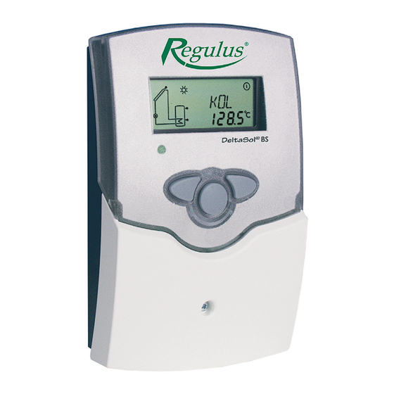
Summary of Contents for Regulus RESOL DeltaSol BS/3
-
Page 1: Imprint
Mounting - Connection - Handling RESOL DeltaSol BS/3 Controller version PG68.30 Software version 1.04 v 1.1... -
Page 2: Table Of Contents
Contents Imprint .................2 Security devices ..............2 Technichal data and function survey .........3 2.2.3 System screen ................. 8 Installation .............5 Blinkcodes ................8 Mounting .................. 5 2.3.1 System-Screen Blinkcodes ........... 8 Electrical wiring ..............5 2.3.2 Blinking codes ................. 8 1.2.1 Standard solar system ............ - Page 3 • system-monitoring-display • system-monitoring-display • up to 4 temperature sensors • up to 4 temperature sensors Pt1000 • user-friendly operation by simple handling • heat balancing heat balancing • 1 or 2 relay-controlled loads • function control function control • user-friendly operation by user-friendly operation by •...
-
Page 4: Installation
Installation display Warning! 1.1 Mounting Switch-off power supply before opening the housing. The unit must only be located internally in a dry place. The unit must only be located internally. It is not suitable It should not be sited near to any electromagnetic fi eld. for installation in hazardous locations and should not be The controller must additionally be equipped with a circuit cover... -
Page 5: Standard Solar System
Arr 1 1.2.1 Allocation of clamps for system 1 Standard solar system with 1 store, 1 pump and 3 sen- sors. The sensor S4 / TRL can optionally be used for heat quantity balancing. ANL 1 Symbol Specifi cation Collector sensor Store sensor below Store sensor at the top (optionally) -
Page 6: Operation And Function
Operation and function 2.1 Pushbuttons for adjustment The controller is operated by 3 pushbuttons below the display. The forward-key (1) is used for scrolling forward through the indication menu or to increase the adjustment values. The backwards-key (2) is accordingly used for the reverse function. -
Page 7: System Screen
2.2.3 System screen The system screen shows one of the 2 system schemes The system screen (active system scheme) shows the selected on the controller. It consists of several system schemes selected on the controller. It consists of several component symbols, which are - depending on the current system component symbols, which are - depending on the status of the system - either fl... -
Page 8: Commissioning
3. Commissioning On commissioning you have to adjust primarily the matching system 1. Ac power supply must be activated. The controller passes 1. Ac power supply must be activated. The controller passes an initialisation phase in which the operating control lamp an initialisation phase in which the operating control lamp fl... -
Page 9: Control Parameter And Indication Channels
Controller parameter and indication channels 4.1 Channel-overview Legend: Corresponding channel is only available if the option heat Corresponding channel is available. quantity measurement is activated (OWMZ). Corresponding channel is available if the appropriate option Corresponding channel is only available if the option heat is activated. -
Page 10: Indication Channels
4.1.1 Indicataion of collector temperatures Shows the current collector temperature. COL: Collector temperature • COL : collector temperature (1-collector-system) display range: -40 ... +250 °C 4.1.2 Indication of store temperatures Shows the current store temperature. TST, TSTL, TSTU: Store temperatures •... -
Page 11: Adjustment Channels
4.1.8 T -regulation Primarily the controller works in the same way as a standard DT O: Primarily the controller works in the same way as a standard differential controller. If the switch-on difference (DT O) is Switch-on temperature differential controller. If the switch-on difference (DT O) reached, the pump is activated. - Page 12 4.1.10 Limit collector temperature If the adjusted collector limit temperature (EM) is exceeded, Collector emergency shutdown the solar pump (R1/R2) is deactivated in order to avoid a damaging overheating of the solar components (collector emergency shutdown). The limit temperature is set to 140 °C by RESOL but it can be changed within the adjustment range Limit collector temperature of 110 ...
- Page 13 4.1.14 Recooling function If the adjustem maximum store temperature (S MX) is reached, the solar pump remains activated in order OREC: to avoid an overheating of the collector. The store option recooling temperature might continue to increase but only up to adjustment range 95 °C (emergency shutdown of the store).
- Page 14 4.1.7 Heat quantity balancing OHQM:Heat quantity balan- A heat quantity balancing is possible for all systems in cing conjunction with a fl owmeter. You just have to activate the Adjustment range: OFF ... ON option heat quantity balancing in the channel OHQM. Factory setting: OFF The volume fl...
- Page 15 4.1.18 Operating mode For control and service work the operating mode of the HAND / HND1 / controller can be manually adjusted by selecting the adjus- HND2: tment value MM, in which the following adjustments can BOperating mode be made: Adjustment range: OFF, AUTO, ON •...
-
Page 16: Tips For Fault Localization
Your claim will be dealt with by your seller at the address shown. Date of Purchase:....Rubber stamp print and signature of the seller: 06/200 REGULUS spol. s r.o. Do Koutů 1897/3 http://www.regulus.eu 143 00 Praha 4 E-mail: sales@regulus.cz...


Need help?
Do you have a question about the RESOL DeltaSol BS/3 and is the answer not in the manual?
Questions and answers