Table of Contents
Advertisement
Quick Links
Advertisement
Table of Contents

Subscribe to Our Youtube Channel
Related Manuals for Regulus TRS 4


Summary of Contents for Regulus TRS 4
- Page 1 Installation, wiring and operating instructions TRS 4 Controller v 1.0...
- Page 2 • Use only original spare parts. • Marking of the manufacturer and distributor must not be altered or removed. • Only the settings actually described in these instructions may be made on the controller. REGULUS - TRS 4 Controller - www.regulus.eu │...
-
Page 3: Table Of Contents
G 1 - Error and info messages ......................G 2 - Replacing the fuse ........................G 3 - Maintenance ..........................G 4 - Useful hints and tricks ......................... G 5 - Disposal ............................REGULUS - TRS 4 Controller - www.regulus.eu │... -
Page 4: A - Description And Installation
Pt1000, type RC21 Sensor leads 2× 0,75 mm extendable up to 30 m Temperature resistance table for Pt1000 sensors: °C Ω 1000 1039 1077 1116 1155 1194 1232 1270 1308 1347 1385 REGULUS - TRS 4 Controller - www.regulus.eu │... -
Page 5: A 2 - Description
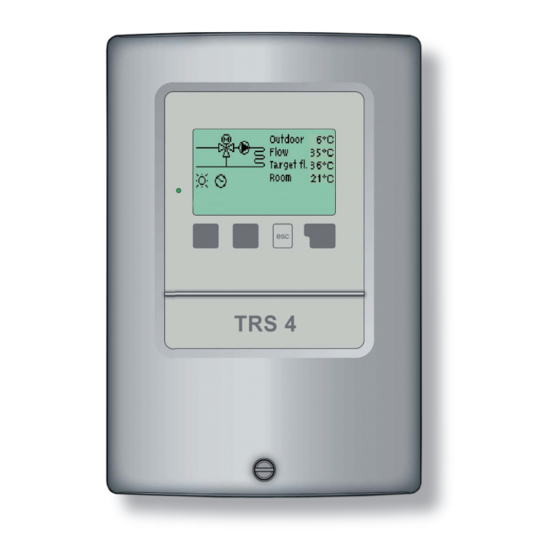
A 2 - About the controller The weather controlled Heating Controller TRS 4 facilitates efficient use and function control of your heating system. This type is designed to control two heating circuits, one mixed and one direct. It is equipped with 5 connection outputs for e.g. -
Page 6: B - Hydraulic Variants
5. Two heating circuits - mixed and direct one, 6. Two heating circuits - mixed and direct one, with boiler, no accumulation tank with boiler and accumulation tank REGULUS - TRS 4 Controller - www.regulus.eu │... -
Page 7: C 1 - Wall Installation
7. Fit the upper part of the housing and insert the other two screws. fixing points 8. Align the housing and tighten the three screws. fixing fixing points points Fig. C 1.2 REGULUS - TRS 4 Controller - www.regulus.eu │... -
Page 8: C 2 - Electric Wiring
S6 shall be removed. If an external thermostat is connected, its Caution electrical contacts shall be of floating type and low resistance = circa 0 Ohm. REGULUS - TRS 4 Controller - www.regulus.eu │... - Page 9 Note: If the hydraulic variant 4, 5 or 6 (page 5) is used, then the sensor of heating circuit 2 shall be connected to terminal S3. If an accumulation tank is used, the sensor can be connected to terminal S4 (see menu 7.4). REGULUS - TRS 4 Controller - www.regulus.eu │...
-
Page 10: E - Controller Use
YES/NO confirm/reject night mode by RC21 Info additional information Back to previous screen confirm setting Reference value mode Reference value 14 day Warning / Error message Warning / Error message Additional heating REGULUS - TRS 4 Controller - www.regulus.eu │... -
Page 11: E 2 - Menu Sequence And Menu Structure
8. Sensor calibration, Remote controller, Mixing valve etc. 9. Lock against unintentional setting changes 9. Menu lock 10. Service Data 10. For diagnosis in the event of an error 11. Language selection 11. Language REGULUS - TRS 4 Controller - www.regulus.eu │... -
Page 12: E 3 - Commissioning Help - Setup Wizard
Observe the explanations for the individual parameters on the following pages, and check whether further settings are necessary for your application. Caution Settings for heating circuit 2 are not included in the Setup wizard. These settings shall be adjusted in Menu 6 „HC2 Settings”. Caution REGULUS - TRS 4 Controller - www.regulus.eu │... -
Page 13: F - Menu Description
In this case the display values can be compensated for using the function of sensor compensation - see 8.1. What measurement values are displayed depends on the selected program, sensors connected and the specific controller model. REGULUS - TRS 4 Controller - www.regulus.eu │... -
Page 14: F 2 - Statistics
Display of the last three errors in the system with indication of date and time. F 2.7 - Reset / clear menu 2.7 Resetting and clearing the individual statistics. Selecting „All statistics” clears everything except for the error log. REGULUS - TRS 4 Controller - www.regulus.eu │... -
Page 15: F 3 - Times
Setting range: One time range for each day of the week Default: Mo-Su off Note: See 5. for the associated temperature settings REGULUS - TRS 4 Controller - www.regulus.eu │... -
Page 16: F 4 - Operating Modes
At the same time, the current measurement values of temperature sensors are also shown in the display for the purposes of function control. REGULUS - TRS 4 Controller - www.regulus.eu │... - Page 17 In the first menu 4.7.1 the starting time of the program is shown. To start the program, press restart. Pressing „restart” again will reset the 14 day reference program and start it at day 1. REGULUS - TRS 4 Controller - www.regulus.eu │...
-
Page 18: F 5 - Settings Hc
-12 °C. The intersection results in a slope of 1.2. The following settings can be used for parallel shift of the characteristic for certain time periods such as daytime and Caution nighttime mode. REGULUS - TRS 4 Controller - www.regulus.eu │... - Page 19 Danger It is recommended to install sensor 4 in the accumulation tank at the same level (or below) of the heating circuit conduit to prevent unnecessary switching of the additional heating. Danger REGULUS - TRS 4 Controller - www.regulus.eu │...
-
Page 20: F 6 - Settings Hc 2
The comfort temperature boost is added to the set day correction. In this manner it is possible to carry out quick heating and/or a higher temperature in the living spaces at a certain time each day. Setting range: from 0 °C to 15 °C Default: 0 °C = vyp. REGULUS - TRS 4 Controller - www.regulus.eu │... -
Page 21: F 7 - Protective Functions
This feature is used e.g. to protect underfloor heating. Setting range: 30 °C to 105 °C Default: 45 °C Set this to activate the 2nd heating circuit. Caution REGULUS - TRS 4 Controller - www.regulus.eu │... -
Page 22: F 8 - Special Functions
The mixing valve is switched on i.e. is opening or closing for the time span set here, then the temperature is measured to control the flow temperature. Settings range: 0.5 sec to 3 sec. Default: 2 s REGULUS - TRS 4 Controller - www.regulus.eu │... - Page 23 „room controller”. If „room controller” is set to 0 %, this function is deactivated. Setting range: 10 °C to 30 °C Default: 20 °C REGULUS - TRS 4 Controller - www.regulus.eu │...
-
Page 24: F 9 - Menu Lock
F 8 - Menu lock F 9 - Service values To block the other menus, select „Menu lock on”. To enable the menus again, select „Menu lock off”. Setting range: on, off Default: off REGULUS - TRS 4 Controller - www.regulus.eu │... -
Page 25: F 10 - Service Values
10.50 10.80 10.21 10.51 10.81 10.22 10.52 10.82 10.23 10.53 10.83 10.24 10.54 10.84 10.25 10.55 10.85 10.26 10.56 10.86 10.27 10.57 10.87 10.28 10.58 10.88 10.29 10.59 10.89 10.30 10.60 10.90 REGULUS - TRS 4 Controller - www.regulus.eu │... -
Page 26: F 11 - Language
Means that either the sensor, the sensor input at the controller or the connecting cable is/was defective. (Resistance table see chap. A6) Restart Means that the controller was restarted, for example due to a power failure. (Information only) Check the date&time! REGULUS - TRS 4 Controller - www.regulus.eu │... -
Page 27: G 2 - Replacing The Fuse
- Check the error memory (see 2.6) - Verify/check plausibility of the current measurement values (see 1) - Check the switch outputs/consumers in manual mode (see 4.3) - Possibly optimize the parameter settings REGULUS - TRS 4 Controller - www.regulus.eu │... -
Page 28: G 4 - Useful Hints And Tricks
WEEE registration number: 02771/07-ECZ disposal service, or the shop where you purchased the product. 06/20 6 /20 REGULUS spol. s r.o. Do Koutů 1897/3 http://www.regulus.eu 143 00 Praha 4 E-mail: sales@regulus.cz REGULUS - TRS 4 Controller - www.regulus.eu │...
Need help?
Do you have a question about the TRS 4 and is the answer not in the manual?
Questions and answers