
Subscribe to Our Youtube Channel
Related Manuals for Regulus IR 07


Summary of Contents for Regulus IR 07
- Page 1 Instruction Manual Electronic Intelligent Heating Regulator Type: IR 07 IR 09 KTP Version: 4.1 11.11.2009 Applicable for software: DP18X v1DP20, v1DP22 Version 1.1...
-
Page 2: Table Of Contents
Table of Contents 1. Caution, Safety, Warranty ........................ 2. Technical Specifications ........................3. Operation of IR07, IR09KTP Regulators ..................4. Regulator Setting ..........................4.1 Setting of Actual Date and Time .................... 4.2 Temperature Setting ......................4.3 Setting of Programs ....................... 4.4 Setting of Week ........................ -
Page 3: Caution, Safety, Warranty
Caution: Keep the Manual for later use and consultation. Carefully read and understand the manual before use! The Regulus intelligent regulators are designed in compliance with latest technologic trends and recognized safety-technical rules. Correct operation of the regulator is based on adhering to the Instruction Manual and its usage in compliance with its intended use. - Page 4 Table. 1.a Positions of Outputs Switch Max. values Unit Note Terminals V ac Output for mixing d6-d9 Solid state relay Three-point control servo-valves e1-e8 (SSR) V ac/dc a2-a9 Acc. to inputs – see Other outputs relay c2-c9 Table 1.b. DC output V dc Table.
- Page 5 I/O connection of IR09KTP regulator: Sensors DATA Source 4 Sensors GDN Source 3 Output 9 VDC Circulation pump DHW RS485 (b) Pool RS485 (a) Solar circuit 2 Termination RS485 (100Ω) Solar circuit 1 Short-circuit coupler for b1 Source 2 Source 1 Common power supply (L) Common power supply (L) Common power supply (L)
- Page 6 Example of electric connection of regulator to heating system on page 7:: │...
- Page 7 Example of hydraulic connection of heating system with IR09KTP regulator: Zone Outdoor Recirculation Pool Source 1 Source 1 │...
- Page 8 Connectin of inputs/outputs for IR07KTP regulator: Sensor bus DATA Output 25 (source 2) Output 24 (source 1) Common power supply of outputs Termination for RS485 Common power supply of outputs Input 40 (source 1 230VAC) Input 40 (source 1 230VAC) Output 5 (servo circ.2 Z) Output 4 (servo circ.2 O) Input 41 (HDO 230VAC)
-
Page 9: Operation Of Ir07, Ir09Ktp Regulators
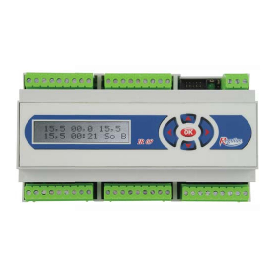
3. Operation of IR07 / IR09KTP Regulators: The regulator is controlled by means of five buttons on case panel of the IR07/IR09 regulator. Pressing of ◄ (button (left arrow) in display menu switches over between displaying of individual zones. Ar- rangement of zones and description of displayed data is on diagram 1. - Page 10 Temperature of source 2 at output Temperature of source 2 at input active Pump running active Source K2 Requirement to source switching none active Status of source constant on Source identification active Requirement to source switching active Status of source 2 Source K3, K4 active Status of source...
- Page 11 When empty position is shown on the display: then no sensor is loaded or connected in this position. Setting of required temperatures in displayed zone may be manually changed by means of ▲ and ▼buttons, maximum possible change is ±10 °C from the value set by program. Such modified value then applies only to another time change within the program.
- Page 12 Movement, temperature setting and zone control . Required temperature Actual temperature in zone Required temperature in zone Temp. of heating water in zone Outer temperature Zone 1-4 Time Day in week Status of zone Status of zone Zone identification (Z1-Z4) EXCEPTION enter to menu...
- Page 13 Date Time Circulation Day in week zone Status of pump constant Status of zone Status of zone Zone identification (C) EXCEPTION enter to menu Required temperature Temperature of water in pool Required temperature Temp. in accum. tank (Aku1h sensor) Pool Outer temperature zone Time...
-
Page 14: Regulator Setting
4. Regulator Setting: Diagram of regulator setting process: Connection of regulator Temperature setting Setting of actual time to power supply (section 4.2) and data (section 4.1) (section 1; 2) Setting of programs Setting of week Setting of bank holi- (section 4.3) (section 4.4) days (section 4.5) Setting of exceptions... -
Page 15: Setting Of Actual Date And Time
4.1 Setting of Actual Date and Time: Note: Actual time and date must be set in regulator, as programmed regulations is controlled by the time and date. Setting: • Pressing of ► button enters the basic menu (first EXCEPTION tab is displayed); move to DATE AND TIME tab by ▲... -
Page 16: Setting Of Programs
4.3 Setting of Programs: Note: The program determines change of required temperature (from preset values – see section 4.2) in se- lected time period. Caution: The regulator starts to regulate to set temperature is specified time; the temperature will be achieved with delay based on size and nature of the space. -
Page 17: Setting Of Week
4.4 Setting of Week: Note: This item selects one of six programs for each day in week within defined zone. Setting: • Pressing of ► button enters basic menu (first EXCEPTION tab is displayed); move to WEEK tab by ▲ and ▼... -
Page 18: Setting Of Equitherm Curves
4.6 Setting of Equitherm Curves: The equitherm curves (equitherms) serve for entering of relation of heating water to outer temperature. The relation requires at least 2 points entered to create equitherm curves of line shape (see Example 1). By means of two points, we are able to set steepness and shift of the line. -
Page 19: Setting Of Exceptions
Setting: • Pressing of ► button enters basic menu (first EXCEPTION tab is displayed); move to EQUITHERMS tab by ▲ and ▼ button. • Press ►. Following is displayed: Cursor Outer temperature Selection Temperature of heating water of zone • Select a zone by means of ▲ and ▼ buttons. •... -
Page 20: Solar Circuit Data Display
4.8 Solar Circuit Data Display: Display procedure: • Enter the basic menu by means of ► button, first EXCEPTION item is selected. • Select MEASURED VALUES by means of ▲ and ▼ zbutton and press ►. • Select the displaying of solar field 1 data (S1) or solar field 2 data (S2) by means of ▲ and ▼. The display will show data on selected solar field, actual power of the field (kW), flow through selected solar circuit (l/min) and solar intensity (%): Insolation... -
Page 21: Regulator Configuration Settings - Service Settings
5. Regulator Configuration Settings – Service Settings: The Configuration submenu serves to setting of zones, sources, regulation and loading of sensors. CONFIGU- RATION item is available only in the service mode. This setting may be made only by trained qualified person (service technician). -
Page 22: Zone Settings
5.2 Setting of Zones: Note: Individual zones differ by number, as well as type of set parameters. Setting: • In the configuration menu, select the ZONE item by means of ▲ and ▼ button, then press ► button. • Select required zone from the zone listing (see table 5.1) by means of ▲ and ▼ button and then press ► button. - Page 23 Effect of spatial t (%) (Vli prostor.t): Parameter entered only in equitherm regulation type. - Setting of proportional parameter G affecting change of heating water temperature in relation to difference between actual and required temperatures within a zone acc. to following equation: ∆t = (w - y).0,8.G (w - required temperature;...
- Page 24 Prostor.t P.k (%) (Spatial t Pc): Parameter entered only in PID regulation type (no effect for control to constant water temperature). - Setting of PID regulation proportional constant. Prostor.t I.k (%) (Spatial t. Ic): Parameter entered only in PID regulation type (no effect for control to constant water temperature). - Setting of PID regulation integral constant.
-
Page 25: Description Of Individual Parameters For Tuv Zone
Valve switching ON Fig. 4 Dobeh cerpadla (Pump rundown)(min): - Setting of rundown time for zone circulating pump. Regul. t pomoci (regula. time by): cerpadla pump - Circulating pump of direct heating circuit is switched ON in relation to requirement to heating water temperature. ventilu valve - Requirement to heating water temperature into the... -
Page 26: Description Of Individual Parameters For Tuve Zone
5.2.3 Description of individual parameters for DHWE zone: Note: Domestic hot water (DHW) is heated in the tank by electric heating element. The heating element is switched ON upon decrease of temperature at sensor TUHv below required temperature in zone, the element is switched OFF upon increasing of zone required temperature by fix set difference 3K. -
Page 27: Description Of Individual Parameters For Cir Zones
Min.t do zony (°C) (Min t to zone) (°C): - Setting of minimum temperature to zone. Note: If user sets the BAZ zone temperature below the temperature set in parameter Min t to zone, the circulating pump switches OFF. Blok zonu pod (°C) (Zone block below): - If the temperature on sensor selected in parameter “SOURCES MENU-SOURCE X Selection of sensor block”... - Page 28 Cas blokace 2 (min.) (Block time): Note: The parameter is set for SOURCE2 in mode “Auto” or “Combined”. - Setting of block time delay for switching the second source ON from request to switching the sources ON (source 1 switches ON automatically) Dif.pro zap (°C) (Dif for ON): - Setting of temperature difference between required heating water temperature calculated by regulator and temperature...
- Page 29 Table 5.4 Sensor Description Outdoor Outdoor sensor Zone 1 Spatial sensor in zone 1 Zone 2 Spatial sensor in zone 2 Zone 3 Spatial sensor in zone 3 Zone 4 Spatial sensor in zone 4 Z1 heat Heating water temperature sensor in zone 1 Z2 heat Heating water temperature sensor in zone 2 Z3 heat...
- Page 30 Podmíněné HDO (Conditioned HBO): - Switching source ON is conditioned by HDO signal. - Switching source ON doe sot depend on HDO signal. t. vratu (°C) (Return t): - Setting of source return water temperature. t. pretopu (°C) (Overheat t): - Setting of source overheat temperature.
- Page 31 Vent.omez. d sl. (Valve der comp limit): Zapnuto - Limits derivation component D of valve regulation intervention in such manner that regulation intervention is not applied in case of opposite sign (see section 7.1). Vypnuto - Derivation component D of regulation intervention is not limited Ventil D konst.
-
Page 32: Description Of Individual Parameters For Zdroj3 And Zdroj4 Sources
5.3.2 Description of individual parameters for SOURCE3 and SOURCE 4 sources: Typ zdroje (source type): auto Auto - Source is switched ON automatically by regulator acc. to set temperature difference. vypnut - Source is switched OFF. Čas blokace 3(min.) (Block time): Čas blokace 4(min.): - Setting of block time of switching the 3 , resp. -
Page 33: Other Parameters Of Sources Menu
5.3.3 Other parameters of SOURCES menu: Havarijní t. AKU (°C) (ACU emergency t): vypnuto - Emergency cooling system switched OFF. 0-120 °C - Setting of maximum temperature of accumulation tanks (Sensed by sensor AKU1h-AKU4h); on exceeding the set temperature the emergency cooling of system is switched OFF. Maximum temperatures of individual zones remain unchanged. - Page 34 Dif. t okruh1 ZAP(°C) (Dif t circuit 1 ON): - Setting of temperature difference for switching the first circuit solar heating ON. Dif. t okruh1 VYP (°C) (Dif t circuit 1 OFF): - Setting of temperature difference for switching the first circuit solar heating OFF.
- Page 35 Cas t1 (min.) (Time t1): Parameter entered only in alternate heating type. - Setting of time delay for alternate heating, when the regulator detects the collector temperature increase. Note: Detailed description of alternate heating function is given in Annex. Cas t okruhu2 (min.) (Time t circuit 2): Parameter entered only in alternate heating type.
- Page 36 Dif.t nom.okr2 (°C) (Dif t nom circ2): Note: Parameter applies only in use of solar module with regulator IR07, IR09. Parameter entered only for pump speed control type: acc. to insolation. - Setting of temperature difference between solar circuit 2 (appliance 2) and solar field, when the pump speed is increased by one step (10%).
- Page 37 Zpozdeni (min) (Delay): Note: Parameter applies only in use of solar module with regulator IR07, IR09. Parameter entered only for pump speed control type: acc. to quick heating of upper part of appliance. - Setting of delay , for which the regulator measures temperature difference between solar field and upper part of actual appliance.
-
Page 38: Setting Of Regulace Zone
Krit.t kol (°C) (Crti coll): - Setting of collector critical temperature. On exceeding of the temperature the solar pump switches OFF to prevent damage of solar components. Protimraz.fc.kol (°C) (Coll antifreeze fun): vypnuto - Collector anti-freeze protection function is OFF. -20 - 10 °C - If the collector temperature decreases below set temperature, solar pump switches ON. - Page 39 Table 5.4 Sensor Description Outdoor Outer sensor Zone 1 Spatial sensor in zone 1 Zone 2 Spatial sensor in zone 2 Zone 3 Spatial sensor in zone 3 Zone 4 Spatial sensor in zone 4 Z1 heat Heating water temperature sensor in zone 1 Z2 heat Heating water temperature sensor in zone 2 Z3 heat...
- Page 40 Loading of sensor to regulator: Note: Each sensor is provided with its own address and logs into the regulator upon connection to bus. The sensor loading must be executed successively and separately. Note: One sensor may be loaded to more positions (such as Aku1p and Aku1s). •...
-
Page 41: Description Of Other Parameters For Regulace Zone
Clearing of sensors load into the regulator: • Disconnect all sensors or only selected sensor from the regulator. • Proceed similarly as during the sensor loading process; select sensor, which is to be cleared, and fol- low the procedure for its loading. As no sensor is connected, the sensor is assigned with address 0000000000000000 and thus the sensor is cleared. -
Page 42: I/O Testing
5.5.3 Testing of inputs and outputs: Setting: • - In the REGULATION menu, select TEST item by means of ▲ and ▼ buttons. The display shows: Inputs Outputs • - The INPUTS field shows status of inputs at the moment of TEST item displaying (see table 5.5). Du- ring the displaying, the inputs are not updated, for actual status of inputs it is necessary to select another parameter by means of ▲... -
Page 43: Input Function
Table 5.6 Table 5.7 Table with numbers of regulator functions Table with no. of IR07 reg. outputs Function No. IR 07 Output function (Test No.) Output No. Terminal pos. Circuit 3 mixing valve opens Circuit 3 mixing valve closes Circuit 4 mixing valve opens... - Page 44 Table 5.8 Table 5.9 Table factory setting of IR 07 Table with no. of IR09 reg. outputs IR 09 Factory settings of IR07 I/Os Output No. Term. pos. Term. pos. Output No. Function No. Function Source 2 Source 1 Common supply (L)
- Page 45 Table 5.10 Table of factory setting of IR09 regulator Factory settings of IR09 I/Os Terminal pos. Output No. Function No. Function Common supply (L) Source 1 Source 2 Solar circuit 1 pump Switching to solar 2 Pool pump DHW circulating pump Source 3 Source 4 40 (input)
-
Page 46: Configuration Arrangement, Range Of Parameters
6. Arrangement, configuration, range of parameters: Annex: Arrangement, configuration, range of parameters Zones Regul.type Zone 1-4 PID acc. to spatial t Equitherm Const. water T Zone OFF Max.t. 0-99°C Min. t. 0-99°C Blok zonu pod 0-99°C Vliv prostor. t 0-100°C Only for equitherm regulation type Max.pos.pretop 0-99°C... - Page 47 Sources Source 1 auto Manual Combined -15 ÷ X °C Y ÷ 15 °C List of sensor List of sensor Allowed Prohibited List of sensor -50÷50 °C 0-99 °C 0-120 °C 0-120 °C 1-120 °C 0-59 min 0-50 0-100 limited unlimited 0-100 0-100...
- Page 48 One field Two fields List of sensors 0-99 °C 0-99 °C 0-120 °C List of sensors 0-99 °C 0-99 °C 0-120 °C List of sensors 0-99 °C 0-99 °C 0-120 °C Cascade Alternate 0-120 °C 0-120 °C 0-10 min 0-60 min 0-60 min Insolation Heating speed...
-
Page 49: Regulation And Setting Examples
Regulation List od sensors 0-99 °C 0-255 min List od sensors List of sensors -50 ÷ 50 °C -50 ÷ 51 °C Output 0 - 31 Input - function Function - output 7. Examples of regulation and settings: 7.1 Regulation of Mixing Valves: The regulator calculates a regulating intervention of R valve acc. -
Page 50: Equitherm Curve Influenced By Spatial Temperature
The valve regulating intervention is further limited by following parameters: Ventil max.krok (Valve max step): Limits valve opening/closing interval (see figure 8) acc. to following equation: . Ventilmax.krok skut. vyp. Vent.omez.d.sl (Valve der comp lim): Limitation of Roff regulating intervention derivation component. -
Page 51: Quick Heating Function
Changes of heating water temperature given by equitherm curve are limited by parameters “Max.pos.pretop” and “Max.pos.nedotop”, and also by parameters “Max t do zony” and “Min t do zony” (see figure 8b). Equitherm curve Outdoor temperature Fig. 8b Example 1: Setting: proporc.složka=12%;... -
Page 52: Description Of Selected Functions Of Ir09 Regulator And Solar Module
Position 1) For the quick heating function, the Aku1h Location of sensor is located in position 1 (see diagram) Aku1h sensor to achieve the effect, when minimum amount for quick heating of hot water in accumulating tank is used for Heating function heating of selected zones. -
Page 53: Description Of Solar Pump Speed Control For Quick Heating Of Equipment Upper Section
Increase Decrease Increase 8.4 Description of Solar Speed Control for Quick Heating in Upper Part of Appliance: This function requires fitting of “upper sensors” to the appliance sensors, i.e. if the appliance 1 sensor is Aku1s and appliance 2 sensor is DHWs, also the Aku1h and DHWh sensors must be fitted. If switching frequency between solar collector and appliance upper part is achieved, the solar pump is switched ON for 10 sec to full speed –... -
Page 54: Description Of Delivered Heat Measurement Function
8.6 Description of Supplied Heat Measurement: The IR09 solar module is able to measure the heat sup- plied by solar collectors to appliance. In this case, the solar system must include besides the temperature sen- sors on solar collectors also the sensor at input to solar collectors and eventually the flow-meter (see diagram). - Page 55 to/ from from to/ from to/ from to/ from to/ from time temperature Zone time temperature time temperature Zone time temperature time temperature Zone time temperature time temperature Zone time temperature time temperature Zone time temperature time temperature Zone time temperature time temperature...
-
Page 56: Ir07 / Ir09 Testing And Service Software - Ir09 Terminal Program
• Clearing and loading of new firmware; • Clearing and loading of new firmware; The regulator is connected to PC by means of communication cable IR09-PC Regulus (COM-RS232). The program is executable without any installation. Upon start of IR09terminal.exe the program window is displayed, see fig. - Page 57 Monitoring, control and testing of the regulator and check of saved data is done by Ovládání (Control) item and select regulator type (KTP). Select Monitorování (Monitoring) function for communication of regulator with PC (ensure that regulator is connected to PC). Then the program will display actual data (temperatures from relevant sensors and status of inputs and outputs of regulators).
- Page 58 For saving of actual, loading new or back-up configuration, select in IR09terminal the Configuration item (win- dows is displayed as shown on fig. 13). Note: Make sure that recording and monitoring is switched OFF, otherwise the communication between regulator and PC will not be successful during configuration change. Fig.
-
Page 59: System Information
Monitoring of sensors: Program IR09 Terminál enables monitoring of communication with sensors in system. If the sensor monitoring is allowed in REGULATION menu, the right-hand terminal window lists continuously status of communication with sensors along the data line (fig. 15). After the time data there is sequence of characters, where character position corresponds to position of sensor in the table of sensors (table 5.4), i.e. - Page 60 Table 10.1 Field Description Value Meaning Appliance 1 heated No. of actual Spotřebič appliance of Appliance 2 heated solar heating Appliance 3 heated Cool appliance 1 Cool appliance 2 Assessment Cool appliance 3 of requests P1 požad for activity of Appliance 1 is not yet heated solar fiel 1*) Appliance 2 is not yet heated...
-
Page 61: Revisions Of Ir07/Ir09Ktp Instruction Manual - History
11. Revisions to IR07/IR09 Installation Manual – History Changes from version 3.0 (08.08.2008) to version 3.1 (22.02.2009) 1. Adding of history of revision and modifications (p. 59) 2. Modification of Table 5.6 Functions and outputs (p. 42) 3. Removal of separate test table (p. 42) 4. -
Page 64: Warranty Certificate
THE WARRANTY PERIOD COVERS 24 MONTHS FROM PUTTING INTO OPERATION, HOWEVER MAXIMUM 30 MONTHS FROM DATE OF SALE. REGULUS SPOL. S R.O. (LIMITED) DECLARES THAT IT HAS ADOPTED SUCH MEASURES ENSURING COMPLIANCE OF ALL PRODUCTS PUT INTO MARKET WITH TECHNICAL DO- CUMENTATION.
Need help?
Do you have a question about the IR 07 and is the answer not in the manual?
Questions and answers