
Related Manuals for Honeywell Vertex Edge


Summary of Contents for Honeywell Vertex Edge
- Page 1 USER MANUAL Vertex™ Edge 72 Point Continuous Monitor 1998 2000 Rev A1 ENG ©2020, September...
-
Page 3: Table Of Contents
Optional Installation Step 2: Floor Mounting Installation Step 3: Installing Sample Lines Installation Step 4: Installing the Pump Exhaust Line Installation Step 5: Electrical Power Installation Step 6: Data Acquisition System Device Operations Getting Ready for the Start-up Vertex Edge System User Manual... - Page 4 Maintenance Maintenance Schedule Advance the Chemcassette Tape Replace the Chemcassette Replace an Analyzer Install an Analyzer Return to Service Replace a Pump Clean the Touchscreen Clean the Optics Additional Information Specifications Detectable Gases Maintenance Faults Vertex Edge System User Manual...
- Page 5 Instrument Faults Information Events Manual Analyzer Override Filter Compatibility Nominal Transport Times Replacement Parts & Consumables Network Interfaces and Options HMI PC Security Considerations Warranty Statement Contact Us Vertex Edge System User Manual...
-
Page 6: Safety
General Safety Follow all installation and operational instructions to ensure the safe and reliable operation of this unit. If this monitor is used in a manner not specified by Honeywell Analytics Inc., the protection provided by the equipment could be impaired. -
Page 7: Emc Considerations
Protective conductor terminal (ground terminal) EMC Considerations Your Honeywell Analytics continuous gas monitor has been designed to comply with Electromagnetic Compatibility (EMC) standards applicable at the time of its manufacturing. The design includes filtering, shielding and bypassing techniques. At the time of certification, simulated customer Input/ Output (I/O) schemes were tested. -
Page 8: China Rohs
Continuation of the shield to the cabinet earth ground is most important. Shield For discrete wire terminations, pigtails to the cabinet (connector) Termination ground should be extremely short (no greater than three inches). For multiconductor connector terminations, only 360° shielded shells should be used. Vertex Edge System User Manual... -
Page 9: Connectors
Note: Honeywell Analytics product testing uses >90% braid with foil (around the bundle); twisted pair; stranded 24 AWG (minimum wiring for all qualification and certification testing.) Connectors All qualification and certification of Honeywell Analytics products were achieved with high quality connectors, providing 360° shield coverage. These connectors generally had metal shells. -
Page 10: Introduction
Storing the alarm information in a database. The Vertex Edge System provides fast response to a wide range of gases. Each location may be up to 400 ft (122 m) from the Vertex Edge System. The system uses one or more of Honeywell Analytics’... -
Page 11: System Components
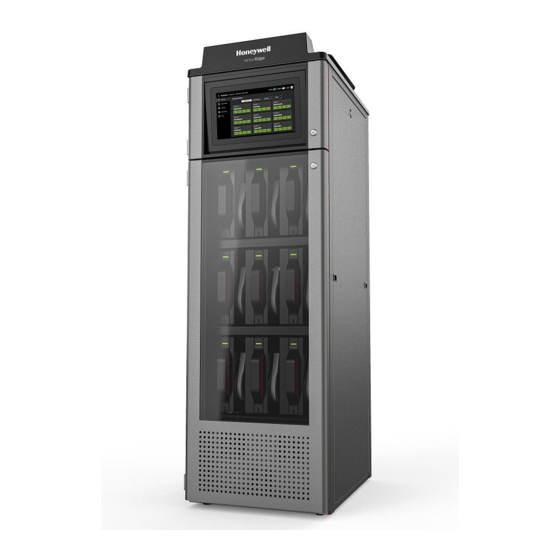
System Components The following photos illustrate the Vertex Edge System views, ports, connections and controls. Front view 1. Sample tubing connections 2. Exhaust and wiring port 3. System controls (behind screen) 4. Analyzer 5. Pump Vertex Edge System User Manual... - Page 12 2. Analyzer 3. Pump Exhaust and wiring ports 1. System Exhaust 0.5 in (12.7 mm) tubing 2. AC Input 0.75 in pipe thread 3. Alarm Wiring Conduit Plates - 4 in (101.6 mm) x 2 Vertex Edge System User Manual...
- Page 13 Module Front - Door Closed 1. Protective panel over touch screen 2. Analyzer Slot 3. Tier 1 4. Tier 2 5. Tier 3 6. Analyzer Status LED Vertex Edge System User Manual...
- Page 14 Analyzer side panel — Exterior Vertex Edge System User Manual...
- Page 15 Needle Valve for flow adjustment Optics Block RFID reader Take-up reel Tape guide roller 1. Analyzer Status LED. 2. Analyzer Release Slot Vertex Edge System User Manual...
- Page 16 Analyzer side panel — Interior 1. Analyzer Main Board 2. Sample pressure transducers 3. Sample flow transducers Vertex Edge System User Manual...
- Page 17 Sample tubing connections Smart Power Distribution Unit Si No Description Si No Description Main Power ON/OFF Switch Rack Fan Power Connector Vertex Edge System User Manual...
- Page 18 Earth Jumper Analyzer Connectors Flow Main Power Connector MON/SBC Pump 1 Power Connector Temperature/flow Pump 2 Power Connector USB/Power Ethernet Hub Power Connector Modbus RTU System Control Unit 1. Single Board Computer 2. Power Distribution Unit Vertex Edge System User Manual...
- Page 19 Analyzer — Front view 1. Analyzer status LED 2. Product label Vertex Edge System User Manual...
- Page 20 Back of Analyzer 1. Internal Ethernet Communication Cable 2. Tubing Harness 3. Analyzer Power Connection Vertex Edge System User Manual...
- Page 21 Chemcassette 1. Chemcassette directional flow Vertex Edge System User Manual...
-
Page 22: Analyzer Modules
• Sample atmosphere runs from the location to the Vertex Edge System via a line • Each of the 72 sample tubing connections on the Vertex Edge System corresponds to a point. A sample line can be connected directly to a single point or multiple points via a 4-port manifold The system draws air simultaneously from all locations. -
Page 23: Chemcassette Detection System
The Chemcassette Analyzer module is a self-contained, microprocessor-controlled analyzer that occupies one slot in a Vertex Edge tier. Sample lines and the vacuum source are connected to the Chemcassette via a single 10-tube connector to develop a better stain for better sensitivity and reliability. - Page 24 When monitoring a location, the system detects and measures a specific gas or a family of gases in the sample. The microprocessor in the analyzer module interprets the data and responds appropriately. In the Closed Loop Optics (CLO) detection system, a reference detector monitors and controls the intensity of the LED. Vertex Edge System User Manual...
-
Page 25: Vacuum Pumps
Note: The exhaust line from the Vertex Edgeshould not exceed 50 feet. The pumps are located in the bottom of the Vertex Edge System cabinet inside a sound- deadening enclosure to reduce noise. Three cooling fans circulate air over the pumps. -
Page 26: Multiple Gas Monitoring
Multiple Gas Monitoring A Vertex Edge System equipped with Analyzers can monitor more than one gas (or groups of gases such as hydrides or mineral acids) at a location. Each Vertex Edge Analyzer module can monitor only one gas family (such as hydrides or mineral acids). -
Page 27: Control Systems
Control Systems The Vertex Edge control system consists of a central data acquisition computer (DAq), and one or more analyzer modules. Following is a simplified block diagram of the communications path of the control system. The analyzer modules are microprocessor controlled and contain non-volatile memory. -
Page 28: Installation
6. Data Acquisition System. Installation Step 1: Surveying the Installation Site A survey of the site helps you to make important decisions before installing your Vertex Edge System. Topics in this section are intended to assist you with appropriate placement of the Vertex Edge System and in determining if you have special filtering needs at the sampling location. - Page 29 Monitor Dimensions Monitor dimensions are important factor in monitor placement. The Vertex Edge System is 24 in. (61 cm) wide, 34-1/2 in. (88 cm) deep and 76 in. (193 cm) in height. The system with 9 analyzers weights about 900 pounds (408 kg). Allow for 24 in. (61 cm) door swing; 5 in. (12.3 cm) at rear and 5 in.
- Page 30 Installation Drawings Vertex Edge System User Manual...
-
Page 31: Optional Installation Step 2: Floor Mounting
Optional Installation Step 2: Floor Mounting 1. Attach the bracket to the front and rear of the Vertex Edge cabinet, including the supplied hardware. 2. Anchor the bracket to the floor with the appropriate mounting hardware base on installation (hardware not provided). -
Page 32: Installation Step 3: Installing Sample Lines
• Unused points require a filter. Filter kit 1295A0702 is recommended. • If an analyzer is installed in the Vertex Edge with a Chemcassette tape, the optics may need cleaning before activating a previously unused point(s). - Page 33 Remove the pipe to measure the insertion depth. CAUTION Improper installation of the tube into the connector results in dilution of the sample. Vertex Edge System User Manual...
- Page 34 Keep in mind that excess amounts of dirt in the filters reduces the sample flow, raises sample vacuum and may affect concentration readings of the analyzer. See Specifications, to determine the proper filter type to use with each target gas. Vertex Edge System User Manual...
-
Page 35: Installation Step 4: Installing The Pump Exhaust Line
Installation Step 4: Installing the Pump Exhaust Line This section describes exhaust connections and installation. The Vertex Edge is equipped with a vacuum pump located at the bottom of the Vertex Edge cabinet. The pump exhaust line connects to the manufacturing facility central toxic exhaust system. -
Page 36: Installation Step 5: Electrical Power
AC Source Requirements: Operating Voltage: 208~240VAC @ 50/60Hz; 15 Amps maximum, single phase. The Vertex Edge System requires a dedicated AC source rated at 208~240VAC @ 50/60Hz, 15 Amp single phase providing hot, neutral, and ground lines. Line voltage should fluctuate no more than ±... - Page 37 Note: After confirming line and neutral connections and the operating voltage is within the specified range, power up the Vertex Edge unit and check the operating voltage again to assure the voltage under load is within the specified range for safe operation.
- Page 38 Secondary, Taps: 2, 2½% FCAN & FCBN Primary Voltage Interconnect Connect Lines to: H3 to H6 H1 and H8 Secondary Voltage Interconnect Connect Lines to: X2 to X3 X1 and X4 Connect X4 to Ground and Shield Vertex Edge System User Manual...
- Page 39 Connect X4 to Ground and Shield Overcurrent Protection Example 1. Primary protection only is required if the transformer is single-phase and the secondary has only two wires. Overcurrent protection rating and location are shown as follows. Vertex Edge System User Manual...
- Page 40 Example 4. If the branch circuit feeding the transformer has overcurrent protection to meet the individual primary overcurrent protection requirements in Example 3, then individual primary protection is not required. Secondary OCP is required as shown as follows. Vertex Edge System User Manual...
- Page 41 (ANSI 61). Ventilated transformer enclosures shall be UL/NEMA Type 1 rated and UL/NEMA Type 3R rated for outdoor use with the addition of a weather shield. This information must be listed on the transformer nameplate. Vertex Edge System User Manual...
- Page 42 301 to 500 KVA 60 db Transformers, 15 KVA to 500 KVA, shall incorporate a UL recognized 2200C insulation system and exhibit a maximum 1500C temperature rise above a maximum ambient of 400C under full load. Vertex Edge System User Manual...
-
Page 43: Installation Step 6: Data Acquisition System
Installation Step 6: Data Acquisition System The data acquisition computer or DAq is the main computer in the Vertex Edge System. The Vertex Edge System can be connected to an external Ethernet network at the port shown. CAUTION Do not connect an external network to the Vertex Edge Ethernet hub. Use only the external Ethernet connection on the back of the data acquisition computer. -
Page 44: Device Operations
Learn what you can do with your Honeywell Vertex™ Edge System Continuous Monitor. Getting Ready for the Start-up Learn the Honeywell Vertex™ Edge system start-up sequence and how to configure the analyzer modules for specific gas locations. Honeywell Analytics loads all software on the DAq at the factory. The Universal Chemcassette Analyzers are configured for the mineral acid family of gases. -
Page 45: Power On
Power On Use the rack power switch behind the touch screen door to power up the Vertex Edge System. 1. Open the touch screen door. 2. Turn on the rack power switch. 3. Turn on the power switch to appropriate analyzers. -
Page 46: Create A Configuration Profile
4. After entering the profile name, you can set or modify values such as: Notification of service due, Events, Timeout, Serial comm, Database, and Analyzers and points. 5. After finishing creating the profile, tap Profile Manager to complete the Creating Profile process. 6. In the Add new profile window, tap SAVE. Vertex Edge System User Manual... - Page 47 7. Tap INSTALL whether you want to install this new profile in the system. 8. Tap INSTALL TO SYSTEM to complete installation. Vertex Edge System User Manual...
-
Page 48: View Analyzer Status
Review general point status of any analyzer. 1. From the main menu, tap Overview. 2. Tap on the selected Analyzer name. General information of each Analyzer's point is displayed. 3. Tap the back overview button to return to the Overview screen. Vertex Edge System User Manual... -
Page 49: View Detailed Analyzer Information
More Info button The Analyzer Information window displays the Serial No. and the Profile ID. 4. Tap View detail. The detailed info is displayed. Use the scroll bar to view the entire content. Vertex Edge System User Manual... - Page 50 5. Optional Step to export the detailed analyzer information. Tap Export. In the File name field, enter a file name for the export process, and then tap NEXT. Select a USB port to export the information, and then tap NEXT. Vertex Edge System User Manual...
-
Page 51: View Detailed Point Data
4. From the detailed point information screen, you can perform several operations such as: Live info. Trend. Scroll left and right on the gas chart. Tap on the chart to view the gas concentration value. customize the range using the slider. Change the time-line. Export as report. Vertex Edge System User Manual... - Page 52 5. Tap the All Points back button to return to the selected Analyzer screen. Vertex Edge System User Manual...
-
Page 53: Acknowledge Notifications
ACK ALL or RESET ALL buttons. The acknowledged event moves to the bottom of the list, and its color diminishes. Vertex Edge System User Manual... -
Page 54: Alternate The Pump Close To Due Date
2. In the pump maintenance window, the uptime is highligted in yellow. Tap Pump Alternate. 3. Tap CONFIRM to start the pump alternation process. 4. Optional step. Tap on the Reset button 5. Tap CONFIRM to reset the counted uptime days. The highlighted uptime resets to zero. Vertex Edge System User Manual... -
Page 55: Turn A Pump On And Off
You can turn ON or OFF a pump when all the analyzers are out of the monitor mode. 1. In the left navigation panel, tap OVERVIEW 2. Tap the pump A/B button 3. In the Pump Maintenance window, tap PUMP OFF or PUMP ON as needed. Vertex Edge System User Manual... -
Page 56: Turn The Monitoring Mode On And Off
3. In the Components status bar, tap on the selected analyzer's name. 4. In the Operation Control window, select Monitoring mode, ON or OFF NOTE The Optic gate is closed when Monitoring mode is ON. Vertex Edge System User Manual... -
Page 57: Open The Optic Gate
3. In the Components status bar, tap on the selected analyzer's name. 4. In the Operation Control window, shift the Optic Gate slider to OPEN. NOTE The Optic gate is closed when Monitoring mode is ON. Vertex Edge System User Manual... -
Page 58: Release The Analyzer Lock
1. In the left navigation panel, tap OVERVIEW 2. Tap on the selected analyzer. 3. In the Components status bar, tap on the selected analyzer's name. 4. In the Operation Control window, tap RELEASE next to Analyzer lock Vertex Edge System User Manual... -
Page 59: Advance The Chemcassette Tape
1. In the left navigation panel, tap OVERVIEW 2. Tap on the selected analyzer. 3. In the Components status bar, tap on the gas family name. 4. In the Operation Control window, tap TAPE ADVANCE next to Chemcassette Vertex Edge System User Manual... -
Page 60: Adjust The Optic Block
Optic Drive, and a Module status in the Optic Block window. Tap ADJUST OPTICS and clean the Optics block by referring to instructions and reset the count. Vertex Edge System User Manual... - Page 61 6. Optional Step. Tap the Reset Count button to Reset the cleaning due days to 180. Vertex Edge System User Manual...
-
Page 62: Adjust The Flow Rate
When the flow reaches the target flow rate of 200cc/min, move to the next point. If the flow adjustment is made for all the points, click STOP FLOW. 7. After completing the flow adjustment, pump can be turned off by referring to section, Turn a pump On and Off. Vertex Edge System User Manual... -
Page 63: Replace The Filter
Either the regular replacement window highlighted in green or the expired time window highlighted in yellow is displayed. 4. Replace the filter manually. 5. Tap the Reset Count button to reset the replacement due days. Vertex Edge System User Manual... -
Page 64: View And Export The Events History Listed By Time
1. In the left navigation panel, tap Event History 2. Tap in the Listed by time tab. A list of all events is displayed. 3. In the Listed by Time screen, you can filter the information and perform the following activities: Vertex Edge System User Manual... -
Page 65: View And Export The Events History By Analyzer
1. In the left navigation panel, tap Event History 2. Tap in the Listed by Analyzer tab. A list of all analyzer events is displayed. 3. Tap on the More Filters button to view the events of specific Points. Vertex Edge System User Manual... -
Page 66: Maintenance
Pump stem and o-ring 6 months Valve filter 1 year Supply Vacuum Filters 3-6 months Alternate Pumps 6 months Optics Cleaning 1 year or as needed System File Maintenance 1 year or as needed Vertex Edge System User Manual... -
Page 67: Advance The Chemcassette Tape
1. In the left navigation panel, tap OVERVIEW 2. Tap on the selected analyzer. 3. In the Components status bar, tap on the gas family name. 4. In the Operation Control window, tap TAPE ADVANCE next to Chemcassette Vertex Edge System User Manual... -
Page 68: Replace The Chemcassette
Replace the Chemcassette Change the Vertex Edge Chemcassette tape for any of the following reasons: Scheduled end-of-tape service Low Chemcassette warning Chemcassette has expired End of Chemcassette 1. In the left navigation panel, tap OVERVIEW 2. Tap on the selected Analyzer. - Page 69 10. When the Chemcassette leader is napped in, the Optics block should be placed between the two “ALIGN” marks on the tape leader. The alignment is essential to adjust and verify the Optics module before gas monitoring. Vertex Edge System User Manual...
- Page 70 13. If the Chemcassetteis a brand-new tape, the Optics module is adjusted and verified while advancing the Chemcassette tape automatically. The results of optics adjustment and verification are shown on the screen. If the tape is not brand new, Optics adjustment and verification steps will be skipped. Vertex Edge System User Manual...
- Page 71 14. After completing the Optics adjustment/Verification, Tap NEXT 15. In the Start Monitoring Mode window, tap START if you want to start the monitoring mode. If not, Tap IDLE. The new ChemCassette information is displayed. Vertex Edge System User Manual...
-
Page 72: Replace An Analyzer
Replace an Analyzer The Vertex Edge rack is designed for quick replacement of major components. You may replace the Chemcassette analyzer while other analyzers continue to monitor. 1. Turn off monitoring mode for the Analyzer to be replaced. In the left navigation panel, tap Runtime Control 2. - Page 73 9. Unscrew the two screws located at the top and bottom of the manifold bracket. 10. Remove the tubing harness (2) carefully and remove internal Ethernet cable (1) and power connector (3) from the Analyzer. Vertex Edge System User Manual...
- Page 74 11. Unlock the latch on the top of the Analyzer and pull out. Vertex Edge System User Manual...
-
Page 75: Install An Analyzer
IMPORTANT: The 2 screws need to be highlighted to fully secure. If these are not tightened, the unit will leak. Return to Service 1. Turn analyzer power switch on. 2. Re-install the Configuration Profile. 3. Install the Chemcassette. 4. Return analyzer to monitor mode in Runtime Options Menu. Vertex Edge System User Manual... -
Page 76: Replace A Pump
Replace a Pump The Vertex Edge System includes two vacuum pumps. One pump operates while the other is idle. You may replace a defective pump while the other pump continues to operate. NOTE You may replace a pump only when the system places it in standby. Do not replace an operating pump. - Page 77 4. Uninstall the electrical connector on the side of the pump. a. Pull the white tab out. b. Push down on the black tab and pull back on the connector. Vertex Edge System User Manual...
-
Page 78: Clean The Touchscreen
Clean the touch screen display with a lightly moistened towel. Do not spray cleaner directly onto the glass. Excess liquid will run down the screen and interfere with operation. Reference your touch monitor manual for any additional information. Vertex Edge System User Manual... -
Page 79: Clean The Optics
1. Open the Optics Block Gate. 2. Remove the Chemcassette. 3. Open the Vertex Edge side panel. 4. Remove tubing (shown in photo) one at the time and blow out with compressed air. 5. Re-secure side panel and reload the Chemcassette. -
Page 80: Additional Information
CHAPTER Additional Information Learn from about strategic information related to the Honeywell Vertex™ Edge Detector. Specifications OVERALL SYSTEM DIMENSION Size 76” x 24” x 35” Weight - Full Full ~900lbs (~408kg) loaded Empty ~655lbs (~297kg) condition Weight - Empty ≤730lbs (331kg) - Page 81 -1000 ft. (–305 m) to 6000 ft. (1829 m) above sea level Pollution degree 2 WIRING REQUIREMENT Power Singe phase power, Minimum 14 AWG Modbus TCP/IP: CAT5 shielded cable or equivalent (RJ45 connector); Digital Modbus RTU: 2-wire stranded, shielded cable or equivalent (24-14 AWG) Vertex Edge System User Manual...
-
Page 82: Detectable Gases
Detectable Gases Vertex Edge System Chemcassette analyzers are continuous monitoring instruments. The initial analysis period listed in the following table varies based on the programmed alarm levels. This period is valid only after the system pulls a new Chemcassette window. Increasing the programmed alarm levels will decrease the initial sample period. - Page 83 Initial Default Default Alarm Analysis Time to 1TLV alarm @ 2TLV con- Family CC Name (P/N) Table Gas Name Alarm Alarm Range Setting Period centration, 10ft sample line Level 1 Level 2 (second) 0.5-1.9 ppb Arsine XP4 (AsH3) Low 2-4.9 ppb 5 ppb 0.5 ppb 0.3 ppb...
- Page 84 500 ppb 1000 ppb 0-2000 ppb (HF) Low Level 200-399 ppb gas) 400-2000 ppb *Due to U.S. Government regulations, this range may be subject to restrictions requiring special licensing for certain countries outside North America. Contact Honeywell Analytics for eligibility information.
- Page 85 Initial Default Default Alarm Analysis Time to 1TLV alarm @ 2TLV con- Family CC Name (P/N) Table Gas Name Alarm Alarm Range Setting Period centration, 10ft sample line Level 1 Level 2 (second) Boron Trifluoride XP4 0.04 0.05-0.99 ppm <45 sec (Alarm @1ppm with 2ppm BF3 0.1 ppm 0.05 ppm 0.1 ppm...
- Page 86 Initial Default Default Alarm Analysis Time to 1TLV alarm @ 2TLV con- Family CC Name (P/N) Table Gas Name Alarm Alarm Range Setting Period centration, 10ft sample line Level 1 Level 2 (second) *Due to U.S. Government regulations, this range may be subject to restrictions requiring special licensing for certain countries outside North America. 1.5 - 49.9 ppm Ammonia XP (NH3) 25 ppm...
- Page 87 Initial Default Default Alarm Analysis Time to 1TLV alarm @ 2TLV con- Family CC Name (P/N) Table Gas Name Alarm Alarm Range Setting Period centration, 10ft sample line Level 1 Level 2 (second) (Low Level) 0.2-1.0 ppm 0.2ppmF2 gas) <45sec (Alarm @ 0.1ppm with 0.2ppmCl2 Chlorine XP-Cl2-II 0.05 0.06-0.24 ppm...
-
Page 88: Maintenance Faults
Maintenance Faults A maintenance fault indicates the Vertex Edge System requires attention but is continuing to monitor. Event Description Set Condition Possible Cause Resolution Check sample line and line filter. Excessive point vacuum due to clog or kniked Clean the sample line and replace sample line filter. - Page 89 Description Set Condition Possible Cause Resolution operation. Check Ethernet connection to HMI Contact Honeywell Analytics Service. Pump failure Rebuild/Replace non-operating pump Single pump Unused slots not plugged Install connector plug on unused slot Pump swap has occurred because vacuum levels fell below operating range...
- Page 90 Electronic problem Contact Honeywell Analytics Service event data Software version New analyzer was installed into the Vertex Edge rack mismatched In a rack, there is at least one analyzer with different SW version that contains a different software revision than the...
- Page 91 Check motor connections to sensor interface PCB in Gate motor driving failure Gate motor sensor reported failure Motor does not operate analyzer Check sensor connection on PCB Contact Honeywell Bad sensor or cable service Poor grounding Replace Analyzer, Contact Honeywell service...
- Page 92 Perform Load CC Operation to recalibrate Optics drive unusually low Optics LED drive < 1000 Optics board defective Replace Analyzer, Contact Honeywell service Analyzer CPU defective Replace Analyzer, Contact Honeywell service Optics LED not properly calibrated Perform Load CC Operation to recalibrate...
- Page 93 Perform Load CC Operation to recalibrate to insufficient optical signal LED degradated Replace the optics block Optics board defective Replace Analyzer, Contact Honeywell service Chemcassette leader not tight or improperly Reload Chemcassette positioned during white to light gray calibration Bad RFID tag...
- Page 94 Contact Honeywell Analytics Service module code Internal fault at PDU Power Distribution Module is providing internal Hardware failure Contact Honeywell Analytics Service module fault code Re-install analyzer software Analyzer SW corrupted Analyzer software failure Software installation failure Replace Analyzer, Contact Honeywell service...
- Page 95 Information Events The Vertex Edge System enters informational and other non-fault events into the event history database. These do not require any action by the user. Use the event history to check the status of the instrument. Event ID Description...
- Page 96 Optics Programmed Successfully 2037 Optics Program Failed 2038 Ctrl Module Programmed Successfully 2039 Ctrl Module Program Failed 2040 PDU Module Programmed Successfully 2041 PDU Module Program Failed 2042 Gas table updated 2043 Rejected gas table file Vertex Edge System User Manual...
- Page 97 2049 Az lacks LIT option (LIT option not purchased) 2050 Alarm/Fault Reset Request 2051 Reset All Alarms and Faults 2052 Reset All Alarms and Faults - Modbus 2053 Az Configuration updated 2054 Point Configuration updated Vertex Edge System User Manual...
- Page 98 DAq. To confirm a non-responsive DAq as opposed to frozen/locked- up, check the clock located in the upper right hand corner of the Vertex Edge HMI window. If the clock is still advancing, then the DAq CPU is not frozen/locked-up and your local Authorized Service Center needs to be contacted for assistance.
- Page 99 Filters have an arrow on the side of the filter pointing in the direction of airflow toward the Vertex Edge System. Replacement of filters is site dependent. Filter A - P/N 780248 Filter B - P/N 1830-0055 Filter C - P/N 1991-0147 The following table shows sample filter requirements.
- Page 100 XP CHLORINE (Extended Play) 1295-0227 XP HYDRIDES (Extended Play) 1295-0226 XP PHOSGENE (Extended Play) 1295-0228 XP AMINES/AMMONIA (Extended Play) 1295-0405 XP MINERAL ACIDS (Extended Play) 1295-0507 XP4-V for AMINES/AMMONIA 1257-9309 XP4-V for CHLORINE 1257-9308 XP4-V for HYDRIDES 1257-9300 Vertex Edge System User Manual...
- Page 101 24VDC Fan Assembly 0220-0023 Tubing, FEP Teflon 0.190" (3/16") I.D. x 0.250" (1/4") O.D. - 1000 ft roll 0235-0109 (304m) Tubing, FEP Teflon 0.190" (3/16") I.D. x 0.250" (1/4") O.D - 400 ft roll 0235-0157 Vertex Edge System User Manual...
- Page 102 Neoprene Isolation Mount 0950-1061 Thermal Switch (170F) 0170-0082 Fan, 24VDC 0220-0023 Vacuum Fitting Assembly - Exhaust 1295K0547 O RING NO.112 VITON BLUE TEFLON COATED 0235-0187 Unused Point Filter Kit - Inlet Extension with Dust Filter 1295A0702 Vertex Edge System User Manual...
- Page 103 Parity (User Selectable) None Even (Default) Stop Bits 2 (when Parity is set to None) 1 (when Parity is set to Odd or Even) Slave ID option Used for each Analyzer (Default 1-9 as shown) Vertex Edge System User Manual...
- Page 104 Modbus TCP IP Configuration DHCP (Default) Static IP: Static IP address, Gateway, DNS Enable or Disable Web interface on port 80 Enable (Default) Disable Encrypted web interface on port 443 Enable Disable (Default) Vertex Edge System User Manual...
- Page 105 We strongly recommend using the Chrome browser to access HMI remotely. HTTPS Connections When making a connection to the Vertex Edge HMI PC via HTTPS, it will be necessary to accept the certificate. A message like the one using Google Chrome will be shown:...
- Page 106 Tap on the Advanced button, and select “Proceed to <some IP> (unsafe).” External Network Security Considerations The Vertex Edge HMI PC is intended ONLY for connection to a private network – no connections from the internet should be allowed. All services not explicitly named above are disabled and filtered via the iptables rules.
- Page 107 Service Order Number and a full description of the fault at buyer’s expense. If no description of the fault is provided, Honeywell reserves the right to charge an investigation fee. If the product is found to be of “no fault”, Honeywell reserves the right to charge an investigation fee and return same product to buyer after the investigation fee and transport cost are reimbursed in full.
- Page 108 After the effective date this warranty supersedes all existing warranty statements and Honeywell makes no other warranty expressed or implied except as stated above. Vertex Edge System...
- Page 109 405 Barclay Boulevard Lincolnshire, Illinois 60069, USA is.gas.techsupport@honeywell.com Tel: +1 847 955 8200 Toll free: +1 800 538 0363 Scan this code for further reference to Vertex Edge Systems on Honeywell Analytics website © 2020, September 01 Vertex Edge System User Manual...
Need help?
Do you have a question about the Vertex Edge and is the answer not in the manual?
Questions and answers