Table of Contents
Advertisement
Quick Links
Advertisement
Table of Contents

Related Manuals for Lowrance Elite FS 7


Summary of Contents for Lowrance Elite FS 7
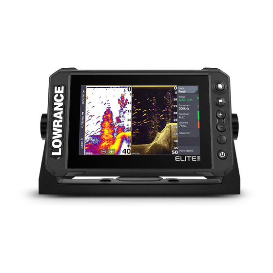
- Page 1 ELITE FS ™ USER MANUAL ENGLISH ELITE FS ™ ELITE FS ™ www.lowrance.com...
- Page 3 Navico Holding AS and other entities. • Navico® is a trademark of Navico Holding AS. • Lowrance® is a trademark of Navico Holding AS. • C-MAP® is a trademark of Navico Holding AS. • ActiveTarget™ is a trademark of Navico Holding AS.
- Page 4 Copyright © 2020 Navico Holding AS. Warranty The warranty card is supplied as a separate document. In case of any queries, refer to the brand website of your unit or system: www.lowrance.com Compliance statements Declarations The relevant declarations of conformity are available at: www.lowrance.com...
- Page 5 Europe Navico declare under our sole responsibility that the product conforms with the requirements of: • CE under RED 2014/53/EU United States of America Navico declare under our sole responsibility that the product conforms with the requirements of: • Part 15 of the FCC Rules. Operation is subject to the following two conditions: (1) this device may not cause harmful interference, and (2) this device must accept any interference received, including interference that may cause undesired...
- Page 6 The latest available manual version and existing addendums can be downloaded from the following website: • www.lowrance.com Viewing the manual on the screen The PDF viewer included in the unit makes it possible to read the manuals and other PDF files on the screen.
- Page 7 The manuals can be read from a storage device connected to the unit or copied to the unit’s internal memory. The following shows an example of a manual file name. Manual file names can vary depending on the unit. Preface | ELITE FS User Manual...
- Page 8 Preface | ELITE FS User Manual...
-
Page 9: Table Of Contents
Contents 17 Basic operation Control keys Turning the system on and off The Home page Application pages Multiple panel pages Menus System controls dialog Screen capture 24 Customizing your system Customizing the Home page wallpaper Adjusting the split on multiple panel pages Data overlay Customizing favorite pages Configuring the quick access key... - Page 10 Using the synchronize feature Waypoints Routes Trails 57 Navigating About navigating Steer panel Navigate to cursor position Navigating a route Navigating with the autopilot Navigation settings 63 Sonar The image Multiple sources Zooming the image Using the cursor on the image Viewing history Recording log data Upload sonar logs to C-MAP Genesis...
- Page 11 Zooming the image Using the cursor on the panel Viewing DownScan history Recording DownScan data Setting up the DownScan image Advanced options More options 83 3D Sonar About 3D Sonar Requirements The 3D panel Zooming the image Using the cursor on a 3D image Saving waypoints 3D mode options Fish renderings...
- Page 12 ActiveTarget scout panel Zooming the image Stopping the Sonar Using the cursor on the panel Recording ActiveTarget video Modes and image settings More options 100 ActiveTarget settings 101 StructureMap 101 About StructureMap 101 The StructureMap image 101 StructureMap sources 102 StructureMap tips 103 Using StructureMap with mapping cards 103 Structure options 105 Instruments...
- Page 13 128 Audio 128 About the audio function 128 The audio controller 128 Setting up the audio system 129 Selecting audio source 129 Using an AM/FM radio 130 Viewing DVD video 131 Radar 131 About radar 131 Supported radar 131 The Radar panel 132 Dual radar 132 Radar overlay 133 Radar operational modes...
- Page 14 156 Sirius status panel 157 Sirius weather panel 157 Showing weather details 158 Local weather 159 Fish mapping overlay 159 Weather options 162 Weather alarms 164 Alarms 164 About the alarm system 164 Type of messages 164 Alarm indication 165 Acknowledging a message 165 Alarm settings 165 Alarm dialogs 166 Internet connection...
- Page 15 179 Software updates 181 Service report 182 Backing up your system data 186 Simulator 186 About 186 Retail mode 186 Simulator source files 187 Advanced simulator settings 188 Integration of 3 party devices 188 SmartCraft VesselView integration 188 Suzuki engine integration 189 Yamaha engine integration 189 Evinrude 189 Power-Pole anchors...
- Page 16 220 Wireless settings 221 Network settings 225 Supported data 225 NMEA 2000 compliant PGN List Contents | ELITE FS User Manual...
-
Page 17: Basic Operation
Basic operation Control keys Pages key • Press once to activate the home page, repeat short presses to cycle the favorite pages. Waypoint key • Press to open the new waypoint dialog. • Press twice to save a waypoint. • Press and hold to access the find dialog. -
Page 18: Turning The System On And Off
Card reader A memory card can be used for: • Chart data • Software updates • Transfer of user data • Logging user data • System backup Ú Note: Do not download, transfer or copy files to a chart card. Doing so can damage chart information on the chart card. -
Page 19: The Home Page
Switch from Standby mode to normal operation by a short press on the Power key. The Home page The Home page is accessed from any operation by a short press on the pages key. Settings Opens the settings dialog. Use it to configure the system. Applications Select a button to display the application as a full page panel. -
Page 20: Application Pages
Application pages Control bar Application panel Menu button Predefined split pages A predefined split page shows more than one application page on a panel. You can adjust the split on a predefined split page. Refer to "Adjusting the split on multiple panel pages" on page 24. Basic operation | ELITE FS User Manual... -
Page 21: Multiple Panel Pages
Favorites bar The favorites bar lists preconfigured pages and favorite pages you have made. Select a favorite page button to open the page. Favorite pages can be single or multiple-panel pages. The favorites bar also provides favorite page editing tools. All favorite pages can be modified. - Page 22 When the touch lock is active, you can still operate the unit from the keys. You remove the lock function by pressing the power key. Lowrance mobile app available The Lowrance mobile app is available for download from the Apple and Play stores. Basic operation | ELITE FS User Manual...
-
Page 23: Screen Capture
Check the app at the app store to see what versions of the operating system are supported. Use the Lowrance mobile app to: • Register your device • Get customer support for your device • Get up-to-date charts and offline maps •... -
Page 24: Customizing Your System
Customizing your system Customizing the Home page wallpaper The Home page's wallpaper can be customized. You can select one of the pictures included with the system, or you can use your own picture in .jpg or .png format. The images can be available on any location that can be seen in the storage browser. -
Page 25: Data Overlay
Data overlay You can have data information as overlay on chart and sonar pages. The data overlay is set individually for each default page, favorite pages and for the predefined split pages. The information can be any data available on the network. You turn overlay data on or off from the system controls dialog. -
Page 26: Configuring The Quick Access Key
Edit favorite pages Select the edit button in the favorite panel and then: • Select the X icon on a favorite button to remove the page • Select the tool icon on a favorite button to display the page editor dialog Configuring the quick access key The key presses for the quick access key can be configured. -
Page 27: Charts
Charts The Chart panel North indicator Vessel Chart range scale Grid lines* Range rings* * Optional chart items. Optional chart items can be turned on/off individually from the chart settings dialog. Chart data The system can be delivered with preloaded cartography. For a full selection of supported charts, visit the product web site. -
Page 28: Selecting Chart Source
will be displayed until you re-insert the card or manually switch back to the preloaded cartography. Selecting chart source Available chart sources are listed in the menu. If you have identical chart sources available, the system automatically selects the chart with most chart details for your displayed region. -
Page 29: Chart Orientation
Chart orientation You can specify how the chart is rotated in the panel. North up Displays the chart with north upward. Heading up Displays the chart with the vessel’s heading (A) directed upward. Heading information is received from a compass. If heading is not available, then the COG from the GPS is used. -
Page 30: Look Ahead
Look ahead Moves the vessel icon on the panel to maximize your view ahead of the vessel. Displaying information about chart items When you select a chart item, a waypoint, a route, or a target, basic information for the selected item is displayed. Select the chart item's pop-up to display all available information for that item. -
Page 31: Find Objects On Chart Panels
The cursor assist function The cursor assist function allows for fine tuning and precision placement of the cursor without covering details with your finger. Activate the cursor on the panel, then press and hold your finger on the screen to switch the cursor symbol to a selection circle, appearing above your finger. -
Page 32: 3D Charts
Activate the cursor on the panel to search from the cursor position. If the cursor is not active, the system searches for items from the vessel's position. Ú Note: You must have a SiriusXM Marine subscription to search for fueling stations. Ú... -
Page 33: Chart Overlay
Genesis live Ú Note: Only available when viewing Lowrance or C-MAP chart source. Genesis live is a real-time feature where the unit creates an overlay of depth contour mapping based on live sonar soundings. The Genesis live sonar soundings are recorded onto and viewed from the unit's memory card. -
Page 34: Map Charts
Genesis live menu options Transparency Adjusts the transparency of the overlay. Contour interval Defines the density of live depth contours shown. Depth palette Controls the color palette used to color the depth areas. • Chart sync – syncs the Genesis live layer to the same palette as the chart depth palette defined in the chart menu (under Chart options, View, Depth palette). - Page 35 strength of currents and tides. This is an important tool when considering planning and navigation of a trip. In large zoom ranges the tides and currents are displayed as a square icon including the letter T (Tides) or C (Current). When you select one of the icons, tidal or current information for that location are displayed.
- Page 36 No Photo overlay Photo overlay, land only Full Photo overlay Photo transparency The Photo transparency sets the opaqueness of the photo overlay. With minimum transparency settings the chart details are almost hidden by the photo. Minimum transparency Transparency at 80 Raster charts Changes the view to that of a traditional paper chart.
- Page 37 • Low - displays basic level of information that cannot be removed, and includes information that is required in all geographic areas. It is not intended to be sufficient for safe navigation. Chart categories Several categories and sub-categories are included. You can turn on/off individually depending on which information you want to see.
- Page 38 Custom Select a row in the Custom shading dialog or the add point option to open the Edit dialog. In the Edit dialog, select a field (Depth, color or opacity field) to specify the depth threshold, color or opacity (transparency) of color shading for the depth. In the following example water depth from 5 meters to 10 meters will be shaded yellow in the chart when Depth 1 is the selected shading in the menu.
-
Page 39: Navionics Charts
Genesis Layer The Genesis Layer displays high-resolution contours contributed by Genesis users that have passed a quality check. This option toggles the Genesis layer on/off on the chart image. Available only if the C-MAP chart contains Genesis Layer data. Navionics charts Some Navionics features require the most current data from Navionics. - Page 40 Minimum transparency Maximum transparency Chart shading Shading adds terrain information to the chart. Fishing range Select a range of depths between which Navionics fills with a white color. This allows you to highlight a specific range of depths for fishing purposes.
- Page 41 No shallow water highlighted Shallow water highlight: 0 m - 3 m Safety depth The Navionics charts use different shades of blue to distinguish between shallow and deep water. Safety depth, based on a selected limit, is drawn without blue shading.
- Page 42 Transparency The SonarChart Live overlay is drawn on top of other chart data. The chart data is completely covered at minimum transparency. Adjust the transparency to allow the chart details to be seen. Minimum depth Adjusts what SonarChart Live rendering treats as the safety depth. This affects the coloring of the SonarChart Live area.
- Page 43 Dynamic tide information Dynamic current information The following icons and symbology are used: Current speed The arrow length depends on the rate, and the symbol is rotated according to flow direction. Flow rate is shown inside the arrow symbol. The red symbol is used when current speed is increasing, and the blue symbol is used when current speed is decreasing.
-
Page 44: Chart Settings
Annotation Determines what area information, such as names of locations and notes of areas, is available to display. Chart details Provides you with different levels of geographical layer information. Easy View Magnifying feature that increases the size of chart items and text. Ú... - Page 45 Select to show or hide the heading and course extension lines for your vessel. Extension length Sets the lengths of the heading and course extension lines for your vessel. For setting extension line lengths on other vessels shown as AIS targets, refer to AIS "Course extension" on page 155. A: Heading B: Course Over Ground (COG) The length of the extension line is either set as a fixed distance, or to...
- Page 46 Refer to "Editing or deleting trails" on page Hide chart Ú Note: This option is only available when Lowrance charts are displayed. If the option is set to ON, the chart (background) is not displayed in the chart panel.
-
Page 47: Waypoints, Routes, And Trails
Using the synchronize feature You can use a browser to sign-in at www.letsembark.io or you can sign-in to your Lowrance app account from your mobile device or tablet to manage (create new, change, move, and delete): •... -
Page 48: Waypoints
Synchronizing To synchronize the MFD data and your Lowrance app account data (includes your data at www.letsembark.io), open the Synchronize my data feature from the System Controls dialog or the Services settings dialog. After sign-in, the system advises the last time synchronizing occurred and the following options are available: •... - Page 49 Saving waypoints Save a waypoint at the cursor position if active or at the vessel's position if the cursor is not active. To save a waypoint: • Press the Waypoint key. Press once to display the New Waypoint dialog. Press twice to quickly save a waypoint. •...
- Page 50 The dialog is activated by selecting the waypoint, and then selecting edit from the menu. The dialog can also be accessed from the waypoints tool on the home page. Deleting waypoints You can delete a waypoint by selecting the delete menu option when the waypoint is activated on the panel.
-
Page 51: Routes
Stop navigating to MOB The system continues to display navigational information towards the MOB waypoint until you cancel the navigation from the menu. Waypoint alarm settings You can set an alarm radius for each individual waypoint you create. The alarm is set in the Edit Waypoint dialog. Ú... - Page 52 Ú Note: The menu changes depending on the selected edit option. All edits are confirmed or cancelled from the menu. Creating routes using existing waypoints A new route can be created by combining existing waypoints from the Routes dialog. The dialog is activated by using the Waypoints tool on the Home page and then selecting the Routes tab.
- Page 53 Compatible cartography includes C-MAP MAX-N+, Navionics+ and Navionics Platinum. For a full selection of available charts, visit www.c-map.com or www.navionics.com. Position at least two routepoints on a new route, or open an existing route for editing. Select the Dock-to-dock Autorouting menu option, followed by: - Entire Route - if you want the system to add new routepoints between the first and the last routepoint of the open route.
- Page 54 Two routepoints selected Result after automatic routing The edit route dialog You can manage routes and routepoints, and change route properties using the Edit Route dialog. This dialog is activated by selecting an active route's pop-up or from the menu by selecting the route then the details option.
-
Page 55: Trails
You can delete all routes from the system using the routes dialog. You can back-up your waypoints, routes and tracks before deleting them, refer to "Maintenance" on page 178. Trails About trails Trails are a graphical presentation of the historical path of the vessel. They allow for retracing where your boat has travelled. - Page 56 Trails settings Trails are made up of a series of points connected by line segments whose length depends on the frequency of the recording. You can select to position trail points based on time settings, distance, or by letting the system position a trail point automatically when a course change is registered.
-
Page 57: Navigating
Navigating About navigating The navigation function included in the system allows you to navigate to the cursor position, to a waypoint, or along a predefined route. If autopilot functionality is included in your system, the autopilot can be set to automatically navigate the vessel. For information about positioning waypoints and creating routes, refer to "Waypoints, routes, and trails"... -
Page 58: Navigate To Cursor Position
Bearing line with allowed off course limit When travelling on a route the bearing line shows the intended course from one waypoint towards the next. When navigating towards a waypoint (cursor position, MOB, or an entered latitude and longitude position), the bearing line shows the intended course from the point at which navigation was started towards the waypoint. - Page 59 • the route dialog When route navigation is viewed, the menu expands and shows options for canceling the navigation, for skipping a waypoint, and for restarting the route from current vessel position. Starting a route from the chart panel Activate a route on the panel, and then select the route navigation option from the menu.
-
Page 60: Navigating With The Autopilot
Navigating with the autopilot When you start navigation on a system with autopilot functionality, you are prompted to set the autopilot to navigation mode. If you choose not to engage the autopilot, the autopilot can be set to navigation mode from the Autopilot Controller later on. For more information about autopilot functionality, refer to "Trolling motor autopilot"... - Page 61 Arrival radius Sets an invisible circle around the destination waypoint. The vessel is considered arrived at the waypoint when it is within this radius. When you are navigating a route, the arrival radius defines the point at which a turn is initiated. The arrival circle (1) should be adjusted according to boat speed.
- Page 62 XTE alarm (Cross track error) Turns on/off the XTE alarm. Trails Opens the Trails dialog where trails settings can be adjusted and trails can be converted into routes for navigation. Refer to "About trails" on page 55. Logging type You can select to record trail points based on time, distance, or by letting the unit position a point automatically when a course change is registered.
-
Page 63: Sonar
Sonar The image Fish arches History preview* Temperature graph* Depth at cursor Amplitude scope* Zoom (range) buttons Water depth and Water temperature at cursor location Range scale Bottom * Optional items that you can turn on/off individually. Refer to "More options"... -
Page 64: Zooming The Image
For more information on how to select the source for a panel, refer to "Source" on page 68. Zooming the image To zoom the image: • Press the +/- keys. • Select the range (+/-) buttons. • Use the range menu setting. When zooming in, the sea floor is kept near the bottom of the screen. -
Page 65: Viewing History
Select the finish measuring menu option to resume normal image scrolling. Viewing history Use the preview feature to view and pan history, refer to "Preview" on page 72. Recording log data Start recording log data You can start recording log data and save the file internally in the unit, or save it onto a storage device connected to the unit. -
Page 66: Upload Sonar Logs To C-Map Genesis
Stop recording log data Use the stop logging option to stop recording log data. Viewing recorded data Both internally and externally stored sounder records can be reviewed when the view sonar log option is selected in the sonar settings dialog. Refer to "Sonar settings" on page 202. Upload sonar logs to C-MAP Genesis To upload sonar logs to C-MAP Genesis do one of the following: •... -
Page 67: Setting Up The Image
Setting up the image Use menu options to set up the image. Fishing mode This feature consists of preset packages of sonar settings designed for specific fishing conditions. Ú Note: Selecting the proper fishing mode is critical to optimal sonar performance. Fishing mode Depth Palette... - Page 68 Custom range This option allows you to manually set both upper and lower range limits. Set a custom range by selecting the range menu option and then the custom option. Ú Note: Setting a custom range puts the system in manual range mode.
-
Page 69: Advanced Options
You can display different sources simultaneously, using a multi- panel page configuration. Menu options for each panel are independent. Ú Note: Using transducers at the same frequency can cause interference. Advanced options The Advanced menu option is only available when the cursor is not active. -
Page 70: More Options
manual mode, you might not receive any depth readings, or you might receive incorrect depth information. More options Stop Sonar When selected, stops the sonar from pinging. Use the option anytime you want to disable the sonar but not power off the unit. Split screens Zoom Zoom level... - Page 71 Bottom lock The bottom lock mode is useful when you want to view targets close to the bottom. In this mode, the left side of the panel shows an image where the bottom is flattened. The range scale is changed to measure from the seabed (0) and upwards.
- Page 72 The amplitude scope is a display of an echo sounding on the panel. The strength of the actual echoes are indicated by both width and color intensity. Preview You can have all available sonar history shown at the top of the sonar screen.
-
Page 73: Sonar Settings
Sonar settings This section only lists user settings, for other installation settings refer to "System setup" on page 197. Sonar | ELITE FS User Manual... -
Page 74: Sidescan
SideScan About SideScan SideScan provides a wide coverage in high detail of the seabed to the sides of your boat. The SideScan panel is available when a SideScan capable transducer is connected to the system. The SideScan panel Left-side bottom Structure on bottom Center water column Right-side bottom... -
Page 75: Using The Cursor On The Panel
• Press the +/- keys. • Select the range buttons. • Use the range menu setting. Using the cursor on the panel When you position the cursor on the panel, the image pauses and the cursor information window is activated. The left/right distance from the vessel to the cursor are shown at the cursor position. - Page 76 Source Ú Note: Available only if multiple sources with the same capability are available. Used to specify the source for the image in the active panel. You can display different sources simultaneously, using a multi- panel page configuration. Menu options for each panel are independent.
-
Page 77: Advanced Options
Advanced options Surface clarity Wave action, boat wakes and temperature inversions can cause onscreen clutter near the surface. The surface clarity option reduces surface clutter by decreasing the sensitivity of the receiver near the surface. Flipping the image left/right If required, flips the left/right side of the image to match the direction of the transducer installation. -
Page 78: Downscan
DownScan About DownScan DownScan provides detailed images of structure and fish directly below your boat. The DownScan panel is available when a DownScan capable transducer is connected to the system. The DownScan panel Surface Fish arch. The fish arches come from the FishReveal feature. The FishReveal feature is enabled by default, but if it is turned off then the fish arches are not shown on the DownScan image. -
Page 79: Using The Cursor On The Panel
When zooming in, the sea floor is kept near the bottom of the screen. To zoom the image (change the range): • Press the +/- keys. • Select the range (+/-) buttons. • Use the range menu setting. Using the cursor on the panel When you position the cursor on the panel, the image pauses and the cursor information window is activated. -
Page 80: Advanced Options
Ú Note: Using transducers at the same frequency can cause interference. Range The range setting determines the water depth that is visible on the screen. Ú Note: Setting a deep range in shallow water may cause the system to lose track of the depth. Preset range levels Select a preset range level manually from the menu. -
Page 81: More Options
Surface clarity Wave action, boat wakes and temperature inversions can cause onscreen clutter near the surface. The surface clarity option reduces surface clutter by decreasing the sensitivity of the receiver near the surface. More options Stop Sonar When selected, stops the sonar from pinging. Use the option anytime you want to disable the sonar but not power off the unit. - Page 82 Ú Note: Palette choice is often a user preference, and may vary depending on the fishing conditions. It is best to select a palette that provides good contrast between the image details and FishReveal arches. Range lines Range lines can be added to the image to make it easier to estimate depth.
-
Page 83: 3D Sonar
3D Sonar About 3D Sonar 3D Sonar is a multi-beam sonar technology that allows anglers to see fish, underwater structures and bottom contours in customizable, three-dimensional views. Requirements The 3D Sonar page is available when a 3D Sonar capable transducer is connected to the system via a 3D sonar module. -
Page 84: Zooming The Image
Zoom panel buttons Contrast Zooming the image You can zoom the image by using the display specific zoom options. If the cursor is active, the system zooms in where the cursor is positioned. Using the cursor on a 3D image By default, the cursor is not shown on the image. -
Page 85: 3D Mode Options
If the cursor is positioned on a 3D image, no depth information is included for the waypoint. The waypoint on a 3D image is drawn with a line beneath it to indicate its point on the sea floor. 3D mode options There are two modes for the 3D panel: •... -
Page 86: Viewing Image History
Viewing image history The highlighted part of the history bar shows the image you are currently viewing in relation to the total image history stored. The history bar appears by default when the cursor is active. You can turn off the history bar, have it always shown at the top of the screen, or have it appear only when the cursor is active. -
Page 87: Advanced Options
Contrast Determines the brightness ratio between light and dark areas of the screen. Ú Note: We recommend that you use the auto contrast option. Palettes Use for selecting the image's color palette. Advanced options Surface clarity Wave action, boat wakes and temperature inversions can cause onscreen clutter near the surface. -
Page 88: More Options
More options Stop sonar Use this option to pause the image. When activated, the transducer continues pinging, and the system continues collecting data. Clear live history Clears existing live history data from the screen and begins showing only the most current data. View lock When enabled, the camera will maintain the set relative rotation from the vessel. -
Page 89: Sonar Settings
Sonar settings Use the sonar settings dialog to make settings to your sonar system. Refer to "Sonar settings" on page 202. 3D Sonar | ELITE FS User Manual... -
Page 90: Livesight
LiveSight Requirements A LiveSight transducer connected to the unit through a performance sonar interface (PSI) module is required. About The LiveSight transducer can be used in forward or down looking mode. The mounting of the transducer determines the mode. When a LiveSight transducer is installed and configured, a LiveSight button is added to the home page. -
Page 91: Zooming The Image
LiveSight forward: distance range scale LiveSight down: width range scale LiveSight icon, indicating beam direction Depth range scale Range grid - the range grid can be turned on/off from the More menu. If a heading sensor is included in the system, the sonar beam icon on forward view is positioned relative to the vessel. -
Page 92: Customizing The Image Settings
Stop recording video When recording a video, the menu changes to show the stop record option. Customizing the image settings The unit comes with different predefined customization modes, used to control the image settings. Changing modes Select the mode button and then the mode you want to use. When the Down or Forward mode is selected the menu expands with options for that mode. -
Page 93: More Options
More options Target trails A target trail indicates the target movement by leaving an afterglow, gradually reducing the intensity over time. The function is useful for quickly assessing the movement of targets relative to your vessel. Palettes Use for selecting the image's color palette. Range grid lines The range grid can be added to the image. -
Page 94: Activetarget
ActiveTarget About ActiveTarget This feature is available if an ActiveTarget transducer and its sonar module are connected to the Ethernet network. When an ActiveTarget transducer and its sonar module are connected to the Ethernet network, the ActiveTarget button is available on the home page. The ActiveTarget transducer can be used in forward (ActiveTarget Forward), down (ActiveTarget Down) or horizontal (ActiveTarget Scout) looking mode. -
Page 95: Activetarget Down Panel
Down range scale (distance below the transducer) ActiveTarget down panel Distance range scale (distance away from the transducer) ActiveTarget icon, indicating beam direction School of fish Underwater brush with schooling fish in and around it School of fish Single larger fish Down range scale (distance below the transducer) ActiveTarget| ELITE FS User Manual... -
Page 96: Activetarget Scout Panel
ActiveTarget scout panel ActiveTarget icon, indicating beam direction Fish Range grid lines, the range grid lines can be turned off/on, and set to straight or arc from the More menu. Distance range scale (distance to the left/right of the transducer) Underwater structure (rock edge) Range scale (distance in front of the transducer) Zooming the image... -
Page 97: Recording Activetarget Video
When you position the cursor on the panel, the image pauses and the cursor information window is activated. The depth and range of the cursor is shown at the cursor position. Recording ActiveTarget video You can record ActiveTarget video to a memory card. All ActiveTarget recordings are done in a standard .mp4 format, making them ideal for playback on a computer or sharing over the internet. - Page 98 Forward mode menu Scout mode menu Down mode menu Auto mode By default the unit is set to Auto mode. In this mode most settings are automated. Down range The down range setting determines the water depth that is visible on the image.
-
Page 99: More Options
Auto sensitivity Auto sensitivity automatically adjusts the sonar return to the optimal levels. Auto sensitivity can be adjusted (+/-) to your preference while still maintaining the auto sensitivity functionality. Ú Note: Auto Sensitivity is the preferred mode for most conditions. Noise rejection Filters out signal interference and reduces on-screen clutter. -
Page 100: Activetarget Settings
You can display different sources simultaneously, using a multi- panel page configuration. Menu options for each panel are independent. Ú Note: The ActiveTarget platform only allows for a maximum of two ActiveTarget transducers on a network and they must be in different configurations. -
Page 101: Structuremap
StructureMap About StructureMap The StructureMap feature overlays SideScan images from a SideScan source on the map. This makes it easier to visualize the underwater environment in relation to your position, and aids in interpreting SideScan images. The StructureMap image StructureMap can be displayed as an overlay on your chart panel. When StructureMap overlay is selected, the chart menu increases to show the StructureMap options. -
Page 102: Structuremap Tips
Live data When live data is selected, the SideScan imaging history is displayed as a trail behind the vessel icon. The length of this trail varies depending on available memory in the unit and range settings. As the memory fills up, the oldest data is automatically deleted as new data is added. -
Page 103: Using Structuremap With Mapping Cards
Using StructureMap with mapping cards StructureMap allows you to maintain full chart capability and can be used with preloaded cartography as well as C-MAP, Navionics, and other third-party charting cards compatible with the system. When using StructureMap with mapping cards, copy the StructureMap (.smf) files to the unit’s internal memory. - Page 104 Frequency Sets the transducer frequency used by the unit. 800 kHz offers the best resolution, while 455 kHz has greater depth and range coverage. Clear live history Clears existing live history data from the screen and begins showing only the most current data. Log sonar data Displays the log sonar dialog.
-
Page 105: Instruments
Instruments About Instrument panels The panels consist of multiple gauges that can be arranged on dashboards. The panels can be created with analog, digital, and bar gauges. Pre-defined dashboards and templates are included. Example: Creating a dashboard Use the new menu option to create your own dashboard. Starting from blank Select to create your own dashboard from scratch. - Page 106 Copying an existing layout Select to copy an existing layout that you have made. Use menu options to name the dashboard and manage gauges on the dashboard. Using a built-in template Select a pre-defined template to create a dashboard. The template dashboards reflect your vessel configuration.
-
Page 107: Selecting A Dashboard
Key operation Use arrow keys to select the item you want to add, and press the enter key. Choosing gauge data Select the gauge in the dashboard and then the info menu option to choose the data to be shown on the gauge. Selecting a dashboard You switch between the dashboards by: •... -
Page 108: Outboard Autopilot
Outboard autopilot Safe operation with the autopilot Warning: An autopilot is a useful navigational aid, but DOES NOT replace a human navigator. Warning: Ensure the autopilot has been installed correctly, commissioned and calibrated before use. Ú Note: For safety reasons a physical standby key should be available. -
Page 109: Outboard Motors Autopilot (Nac-1) Controller
Outboard motors autopilot (NAC-1) controller Control bar Autopilot controller, disengaged Autopilot controller, engaged Mode indication Mode buttons Turns button Mode dependent buttons Standby button Engaging and disengaging the autopilot To engage the autopilot: • Select the preferred mode button Outboard autopilot| ELITE FS User Manual... -
Page 110: Autopilot Indication
The autopilot will engage in the selected mode, and the autopilot controller will change to show active mode options. To disengage the autopilot: • Select the standby button When the autopilot is in standby, the boat must be steered manually. Autopilot indication The autopilot information bar shows autopilot information. - Page 111 Heading hold mode (A) In this mode the autopilot steers the vessel on the set heading. When the mode is activated, the autopilot selects the current compass heading as the set heading. Ú Note: In this mode the autopilot does not compensate for any drifting caused by current and/or wind (W).
- Page 112 NAV mode Warning: NAV mode should only be used in open waters. Prior to entering NAV mode you must be navigating a route or towards a waypoint. In NAV mode the autopilot automatically steers the vessel to a specific waypoint location, or along a pre-defined route. Position information is used to change the course to steer to keep the vessel on the track line to the destination waypoint.
- Page 113 Turning in NAV mode When the vessel reaches a waypoint, the autopilot will give an audible warning and display a dialog with the new course information. There is a limit for the allowed automatic course change to next waypoint in a route: •...
- Page 114 To start a turn • Select the port or starboard button U-turn Changes the current set heading by 180°. When activated, the autopilot is switched to Auto mode. The turn rate is identical to Turn rate setting. C-turn Steers the vessel in a circle. Turn variable: •...
- Page 115 Turn variables: • Course change • Leg distance Square Steers the vessel in a square pattern, doing 90° course changes. Turn variable: • Leg distance S-turn Makes the vessel yaw around the main heading. When activated, the autopilot is switched to S-turns mode. Turn variables: •...
- Page 116 It is recommended to turn on the AP Depth Data Missing alarm when using DCT. When this alarm is activated an alarm will be raised if the depth data is lost during DCT. To initiate a DCT turn • Steer the boat to the depth you want to track, and in the direction of the depth contour •...
-
Page 117: Autopilot Settings
Autopilot settings The Autopilot settings dialog depends on which autopilot computer that is connected to the system. If more than one autopilot is connected, the Autopilot settings dialog shows option for the active autopilot. Chart compass Select to display a compass symbol around your boat on the chart panel. -
Page 118: Trolling Motor Autopilot
Trolling motor autopilot Safe operation with the autopilot Warning: An autopilot is a useful navigational aid, but DOES NOT replace a human navigator. Warning: Ensure the autopilot has been installed correctly, commissioned and calibrated before use. Ú Note: For safety reasons a physical standby key should be available. -
Page 119: The Autopilot Controller For Trolling Motor
The autopilot controller for trolling motor Control bar Autopilot controller, disengaged Autopilot controller, engaged Mode indication List of available modes Record/Save button Mode dependent information Mode dependent buttons Engage/Standby button When the autopilot controller is the active panel, it is outlined with a border. -
Page 120: Autopilot Indication
The autopilot will engage in the selected mode, and the autopilot controller will change to show active mode options. To disengage the autopilot: • Select the standby button When the autopilot is in standby, the boat must be steered manually. Autopilot indication The autopilot information bar shows autopilot information. - Page 121 Waypoint Navigates to the selected waypoint, and then maintains the vessel at that position. Here Maintains the vessel at the current position. Change the position in anchor mode Use the arrow buttons to reposition the vessel when in anchor mode. Each press on a button will move the anchor position 1.5 m (5 ft) in the selected direction.
- Page 122 fits your navigation needs before NAV mode is activated. Refer to "Arrival mode" on page 125. NAV mode options While in NAV mode the following buttons are available in the autopilot controller: Restart Restarts the navigation from the vessel’s current position. Skip Skips the active waypoint and steers towards the next waypoint.
- Page 123 Turn variables All turn patters have settings that you can adjust before you start a turn, or at any time when the boat is in a turn. U-turn Changes the current set heading by 180°. Turn variable: • Turn radius C-turn Steers the vessel in a circle.
-
Page 124: Trolling Motor Speed Control
S-turn Makes the vessel yaw around the main heading. Turn variables: • Turn radius • Course change • Number of legs Trolling motor speed control In Heading lock mode, Nav. mode and in Turn pattern steering the autopilot system can control the trolling motor speed. The set target speed is displayed in the autopilot controller. - Page 125 Chart compass Select to display a compass symbol around your boat on the chart panel. The compass symbol is off when the cursor is active on the panel. Auto hide autopilot bar Controls whether the autopilot information bar is shown when the autopilot is in standby.
- Page 126 Configure the Ghost trolling motor foot pedal keys You can configure three of the actions keys (A, B and C) on the Ghost series trolling motor foot pedal. Select an action from the drop-down list for each of the keys you want to configure.
- Page 127 Trolling motor autopilot| ELITE FS User Manual...
-
Page 128: Audio
Audio About the audio function If a compatible audio server is properly installed/connected and setup with your system, you can use the unit to control and customize the audio system on your vessel. The audio controller The control buttons, tools and options vary from one audio source to another. -
Page 129: Selecting Audio Source
Audio server If multiple audio sources are connected to the same network, one of the devices must be selected as the audio server. If only one device is present, it is the selected audio server by default. Setting up the speakers Ú... -
Page 130: Viewing Dvd Video
Selecting the tuner region Before using FM, AM or a VHF radio, you must select the appropriate region for your location. Radio channels To tune in to an AM/FM radio channel: • press and hold the left or right audio control button To save a channel as a favorite: •... -
Page 131: Radar
Radar About radar Several radar sensors are supported. This chapter describes features and options for a variety of supported radars. The features and options available to you are dependent on the radar antenna(s) connected to your system. Supported radar Halo dome radar is supported. The Radar panel Orientation Range... -
Page 132: Dual Radar
Cursor position window * Optional radar symbology. Radar symbology can be turned ON/OFF collectively from the Radar menu, or individually as described in Radar settings panel. Dual radar You can connect to any combination of two supported radars and see both radar images at the same time. Ú... -
Page 133: Radar Operational Modes
When the radar overlay is selected, basic radar operational functions are available from the Chart panel’s menu. Selecting radar overlay source on chart panels To select the radar source of the radar overlay displayed on the chart panel, use the Radar options and then Source chart panel menu options to select the radar source. -
Page 134: Adjusting The Radar Image
Dual range When connected to a radar with dual range capability, it is possible to run the radar in Dual Range mode. The radar appears in the radar sources menu as two virtual radar sources A and B. Range and radar controls for each virtual radar source are fully independent and the source can be selected for a particular chart or radar panel in the same manner as dual radar described in "Selecting the radar source"... - Page 135 using Harbor and Weather modes because Fast Scan is Off in Weather mode. • The Interference reject setting can affect the interference seen or removed on both ranges. Directional clutter rejection This mode automatically works when GAIN = AUTO and SEA = HARBOR or OFFSHORE.
-
Page 136: Using The Cursor On A Radar Panel
Auto Sea Offset To allow fine tuning of the Sea control while in Auto mode (Auto uses directional adaptive clutter rejection), the Auto setting may be offset. Rain clutter Rain clutter is used to reduce the effect of rain, snow or other weather conditions on the radar image. -
Page 137: Advanced Radar Options
Advanced radar options Menu options can vary depending on your radar's capability. Noise Rejection Sets the amount of noise filtering applied by the radar. Target sensitivity is increased at longer ranges when this control is set to Low or High, but does cause some loss of target discrimination. Ú... -
Page 138: Radar View Options
Ú Note: Maximum speed may not be achieved depending on the radar Settings, Mode, and Range selected. The radar will only rotate as fast as the current control settings allow. Sea State Set the Sea State control according to current sea conditions for best sea clutter rejection. - Page 139 • Diverging targets are blue colored on all radar image palettes. • Approaching target colors on radar image palettes: - Black/Red palette - Yellow - White/Red palette - Yellow - Black/Green palette - Red - Black/Yellow palette - Red Radar overlay palettes on charts •...
- Page 140 0° 0° The examples show the target movement (1-5) over 5 radar scans with the radar in relative motion mode. In example C, own vessel COG is 0°, and speed is 0 knots. In example D, own vessel COG is 0°, and speed is 10 knots. In both examples, the target COG is 270°, and the speed is 20 knots.
- Page 141 Radar symbology Radar symbology defined in the Radar Settings panel can be turned on/off collectively. See the radar panel illustration showing optional radar items. Target trails You can set how long the trails generated from each target on your radar panel remain. You can also turn OFF target trails. Ú...
- Page 142 The North up orientation is not available if no heading source is connected to the radar. If heading data is lost, the system will automatically switch to Head-up orientation. Course up In Course up mode, the top of the bearing scale indicates the ship’s true course measured from north at the time Course up was activated.
- Page 143 Note: True motion is only available when the PPI is in either north up or course up orientation mode. To set to true motion in the MFD, select the Position option in the More menu and then select the True motion option. Offsetting the PPI center You can set the antenna position origin to a different location on the radar PPI.
-
Page 144: Ebl/Vrm Markers
Move the cursor to the preferred offset position, and confirm your selection. EBL/VRM markers The electronic bearing line (EBL) and variable range marker (VRM) allows quick measurements of range and bearing to vessels and landmasses within radar range. Two different EBL/VRMs can be placed on the radar image. -
Page 145: Setting A Guard Zone Around Your Vessel
Placing EBL/VRM markers by using the cursor Position the cursor on the radar image Activate the menu Select one of the EBL/VRM markers - The EBL line and the VRM circle are positioned according to the cursor position. Offsetting an EBLVRM marker Ensure that the cursor is not active. -
Page 146: Marpa Targets
Shape: Sector Shape: Circle Alarm settings An alarm is activated when a radar target breaches the guard zone limits. You can select if the alarm is activated when the target enters or exits the zone. Sensitivity The guard zone sensitivity can be adjusted to eliminate alarms for small targets. - Page 147 Tracking and safe MARPA target with extension lines. Dangerous MARPA target. A target is defined as dangerous when it enters the guard zone defined on the radar panel. When no signals have been received within a time limit a target will be defined as lost. The target symbol represents the last valid position of the target before the reception of data was lost.
-
Page 148: Radar Settings
MARPA alarm settings You can define the following MARPA alarms: MARPA target lost • Controls whether an alarm is activated when a MARPA target is lost. MARPA unavailable • Controls whether an alarm is activated if you do not have the required inputs for MARPA to work (valid GPS position and heading sensor connected to the radar server). - Page 149 Radar symbology You can select which optional radar items that should be turned on/off collectively from the menu. Refer to the Radar panel illustration. Bearings Used for selecting whether the bearing should be measured in relation to True/Magnetic North (°T/°M), or relative to own vessel (°R).
-
Page 150: Ais
About AIS If a compatible AIS (Automatic Identification System) is connected to the system, AIS targets can be displayed and tracked. You can also see messages and position for DSC transmitting devices within range. AIS targets can be displayed as overlay on chart and radar images. The AIS is an important tool for safe travelling and collision avoidance. -
Page 151: Calling An Ais Vessel
By default, the dialog lists targets, arranged by distance to own vessel. You can select to change the sort order, and to display only a selected target type. The vessels dialog also lists received AIS messages. AIS vessel details Detailed information about an AIS target is available from the AIS vessels details dialog. -
Page 152: Ais Sart
The call option is available in the AIS vessel details dialog, and in the vessel status dialog. Refer to "Displaying target information" on page 150. AIS SART When an AIS SART (Search and Rescue beacon) is activated, it starts transmitting its position and identification data. This data is received by your AIS device. -
Page 153: Vessel Alarms
• Save the waypoint - The waypoint is saved to your waypoint list. This waypoint name is prefixed with MOB AIS SART - followed by the unique MMSI number of the SART. For example, MOB AIS SART - 12345678. • Activate the MOB function - The display switches to a zoomed chart panel, centered on the AIS SART position... -
Page 154: Vessel Settings
Moving and safe AIS target with course extension line. Dangerous AIS target, illustrated with bold line. A target is defined as dangerous based on the CPA and TCPA settings. Refer to “Defining dangerous vessels”. Lost AIS target. When no signals have been received within a time limit, a target is defined as lost. - Page 155 need to have your MMSI number entered to avoid seeing your own vessel as an AIS target. Icon filters By default, all targets are shown on the panel if an AIS device is connected to the system. You can select not to show any targets, or to filter the icons based on security settings, distance, and vessel speed.
-
Page 156: Siriusxm Weather
SiriusXM weather Requirements • A WM-4 Navico satellite weather receiver module connected to your system. • A SiriusXM weather package/subscription. For more information, refer to the website www.siriusxm.com/sxmmarine. About SiriusXM weather Ú Note: SiriusXM weather is available for North America only. When a supported Navico satellite weather receiver module is connected to your system and with the appropriate subscription, SiriusXM marine weather information is available. -
Page 157: Sirius Weather Panel
The status panel shows signal strength is indicated as 1/3 (weak), 2/3 (good) or 3/3 (preferred). It also includes antenna status, service level, and the electronic serial number for the weather module. Sirius weather panel Sirius weather can be displayed as an overlay on your chart panel. When weather overlay is selected, the chart menu increases to show the available weather options. -
Page 158: Local Weather
You can also display weather information from the menu when the weather icon is selected and the 'Info - Weather item' menu option is selected. Local weather The local weather dialog shows current weather and weather forecast for your current location. SiriusXM weather| ELITE FS User Manual... -
Page 159: Fish Mapping Overlay
Fish mapping overlay When the Navico WM-4 receiver is connected to your system and with the appropriate SiriusXM marine weather subscription, the Fish mapping overlay option is available. The Fish mapping overlay helps to identify specific areas with the highest likelihood of finding the fish you are seeking to catch. For more information, refer to www.siriusxm.com/sxmmarine. - Page 160 Forecast wind barbs Forecast wind barbs can be shown or hidden on the weather panel. Wind barbs The rotation of the wind barbs indicate the relative wind direction, with the tail showing the direction the wind is coming from. In the graphics below, the wind comes from the northwest.
- Page 161 Hurricane (category 1-5) tracking; past (grey) - present (red) - future (yellow) Tropical disturbance/depression tracking; past (grey) - present (red) - future (yellow) Storm attributes Lightning Watch box location and warning Marine zone location Marine zone Depending on your selected subscription, SiriusXM services includes access to weather reports for U.S.
-
Page 162: Weather Alarms
Adjusting color codes You can define the Sea Surface Temperature (SST) range and wave height color coding. The temperature above warm and below cool values is displayed as progressively darker red and darker blue. Waves higher than the maximum value are indicated with progressively darker red. - Page 163 SiriusXM weather| ELITE FS User Manual...
-
Page 164: Alarms
Alarms About the alarm system The system continuously checks for dangerous situations and system faults while the system is running. Type of messages The messages are classified according to how the reported situation affects your vessel. The following color codes are used: Color Importance Critical alarm... -
Page 165: Acknowledging A Message
Acknowledging a message The alarm dialog options for acknowledging a message vary depending on the alarm: • Close Sets the alarm state to acknowledged. The siren/buzzer stops and the alarm dialog is removed. However, the alarm remains active in the alarm listing until the reason for the alarm has been removed. -
Page 166: Internet Connection
Internet connection Internet usage Some features in this product use an internet connection to perform data downloads and uploads. Internet usage via a connected mobile/cell phone internet connection or a pay-per-MB type internet connection may require large data usage. Your service provider may charge you based on the amount of data you transfer. - Page 167 Connect to the internet Used for connecting to a hotspot which has internet access. When connected, the text changes to include Already connected. Connect your phone/tablet Used for connecting a phone or tablet to the MFD. Refer to "Remote control of the MFD" on page 170. Bluetooth Enables the built-in Bluetooth functionality.
- Page 168 Built-in WiFi Select this option to enable or disable the internal WiFi. Disabling the internal WiFi reduces the unit’s power consumption. WiFi networks Shows the WiFi network connection status. If the MFD is connected to the internet (WiFi hotspot), the hotspot name (SSID) is shown. Built-in hotspot The system turns this on when connecting with another unit.
- Page 169 devices in the network may also be acting as DHCP servers. To make it easy to find all DHCP servers on a network, dhcp_probe may be run from the unit. Only one DHCP device may be operational on the same network at a time. If a second device is found, turn off its DHCP feature if possible.
-
Page 170: Remote Control Of The Mfd
Remote control of the MFD Remote control options The following options are available for remotely controlling your MFD: • a smartphone or a tablet, connected to the same WiFi hotspot as the MFD(s) • a smartphone or a tablet, connected to an MFD acting as a WiFi access point Ú... - Page 171 Connecting to an MFD acting as an access point If you do not have access to a WiFi network, you can connect your phone/tablet directly to the MFD. The MFD network name (SSID) will be displayed as an available network in the phone/tablet. Using the Link app Start the Link app to display MFD(s) available for remote control.
- Page 172 Managing WiFi connected remotes You can change the access level and remove the WiFi connected remote controllers. Remote control of the MFD| ELITE FS User Manual...
-
Page 173: Using Your Phone With The Mfd
Using your phone with the MFD About phone integration The following functions are available when connecting a phone to the unit: • read and send text messages • view caller ID for incoming calls Ú Note: It is possible to use a smartphone to remotely control the MFD. -
Page 174: Phone Notifications
To pair a phone listed as other devices in the device dialog: • select the phone you want to pair, and follow the instructions on the phone and on the MFD When paired, the phone is moved to the paired device section in the dialog. -
Page 175: Phone Troubleshooting
By default, the message list shows all messages. The list can be filtered to show only sent or received messages. Creating a text message Ú Note: This option is not available for iPhones. To create a new text message: • select the new message option in the message dialog To respond to a text message or to a phone call: •... - Page 176 Not possible to connect an iPhone The first time an MFD attempts to connect to an iPhone, the following errors might appear: • connection failing, giving a message saying that the phone is not available for connection • the phone does not list the correct name for the MFD If this happens, try the following: •...
-
Page 177: Managing Bluetooth Devices
See details for how to display the device details in "Managing Bluetooth devices" on page 177. To change the alert setting for the phone notifications, see "Message settings" on page 175. Text messages appearing on the iPhone, but not on the Check that the text app is not open and active on the iPhone. -
Page 178: Maintenance
Maintenance Preventive maintenance The unit does not contain any field serviceable components. Therefore, the operator is required to perform only a very limited amount of preventative maintenance. Checking the connectors Push the connector plugs into the connector. If the connector plugs are equipped with a lock or a position key, ensure that it is in the correct position. -
Page 179: Nmea Data Logging
Continue pressing the waypoint key during power on until the calibration utility screen closes. NMEA Data logging All serial output sentences sent over the NMEA TCP connection are logged to an internal file. You can export and review this file for service and fault finding purposes. - Page 180 Update the software when connected to internet If the unit is connected to internet, the system will automatically check for software updates for the unit and for connected devices. Ú Note: Some software update files might be larger than the space available in the unit.
-
Page 181: Service Report
Update the software from a storage device You can download the software update from www.lowrance.com. Transfer the update file(s) to a compatible storage device, and then insert the storage device in the unit. Ú Note: Do not add software update files to a chart card. -
Page 182: Backing Up Your System Data
Ú Note: There is a 20MB limit for the report attachments. The report can be saved to a storage device and emailed to support. You can also upload it directly if you have an internet connection. Backing up your system data It is recommended to regularly copy user data and your system settings database as part of your back-up routine. - Page 183 Used to export waypoints and routes with a standardized universally unique identifier (UUID), which is very reliable and easy to use. The data includes such information as the time and date when a route was created. User Data File version 4 •...
- Page 184 Select the export option from the menu. Select the appropriate file format. Select the export option to export to the memory card. Ú Note: You can use the storage export-region feature to export the information to a memory card. Next, insert the card into another unit and select the file on the memory card to import it.
- Page 185 Import system settings Warning: Importing system settings overwrites all existing system settings. Connect a storage device to the unit Browse the memory and select the desired backup file to start the import Maintenance| ELITE FS User Manual...
-
Page 186: Simulator
Simulator About The simulation feature lets you see how the unit works without being connected to sensors or other devices. Retail mode In this mode a retail demonstration for the selected region is shown. If you operate the unit when retail mode is running, the demonstration pauses. -
Page 187: Advanced Simulator Settings
Advanced simulator settings The advanced simulator settings allows for manually controlling the simulator. GPS source Selects the file for the simulated GPS data. Speed and Course Used for manually entering values when GPS source is set to Simulated course. Otherwise, GPS data including speed and course come from the selected source file. -
Page 188: Integration Of 3 Rd Party Devices
Integration of 3 party devices Several 3 party devices can be connected to the unit. The applications are displayed on separate panels or integrated with other panels. A device connected to the NMEA 2000 network should automatically be identified by the system. If not, enable the feature from the advanced option in the System settings dialog. -
Page 189: Yamaha Engine Integration
• A Suzuki icon is added to the home page - select it to display the engine instrument panel. For more information, refer to the engine manual or engine supplier. Yamaha engine integration If a compatible Yamaha gateway is connected to the NMEA 2000 network, the engines can be monitored from the unit. - Page 190 Power-Pole controls When Bluetooth is enabled, the Power-Pole button becomes available in the control bar. Select it to display the Power-Pole controller. For pairing Bluetooth devices, refer to "Bluetooth options" on page 167. If you are pairing dual Power-Poles, also review "Pairing with dual Power- Poles"...
-
Page 191: Power-Pole Charge Module
Ú Note: Selecting to Stay connected speeds up access to the controls, but the anchors cannot be controlled from another unit when it is selected. Turn off this option to allow connection from other units. Pairing with dual Power-Poles If dual Power-Poles are installed on your boat, the one that is paired first automatically becomes Port and the second is set to Starboard in the Power-Pole controls. -
Page 192: Bep Czone Integration
Battery and AC source connections Color Indicates Blue Current flow Grey No current flow Emergency power transfer If your engine battery is low and you want to transfer power from the aux battery to the engine battery, select this option. Warning: Using a battery at a very low charge level can damage the battery. -
Page 193: Czone Digital Switching
CZone digital switching A CZone digital switching device can be connected to the NMEA 2000 network and configured to allow control from the control bar of the MFD. The digital switching bar is displayed in the control bar automatically when the CZone digital switching device is configured to be included in the control bar. - Page 194 CZone digital switching control bar If configured and setup properly, the CZone digital switching device can be operated from the control bar. Control bar buttons The button indicates the status of the switch. Off (black) The switch is OFF. On (blue) The switch is ON.
-
Page 195: The Toolbar
The toolbar This chapter includes descriptions for toolbar tools. The toolbar is displayed in the home page. Press the Pages/Home key to display the home page. You can scroll the toolbar to view its options. Waypoints Includes waypoints, routes, and trails dialogs used for managing these user defined items. -
Page 196: Store
Store Connects to the Navico internet store. At the store you can browse, purchase, acquire feature unlock keys, download compatible charts/ maps for your system and much more. Ú Note: The unit must be connected to the internet to use this feature. -
Page 197: System Setup
System setup First time startup When the unit is started for the first time, or after a reset, the unit displays a series of dialogs. Respond to the dialog prompts to make fundamental settings. You can perform further setup and later change settings using the system settings dialogs. - Page 198 Language Controls the language used on this unit. Boat settings Used to specify the physical attributes of the boat. Text size Used for setting the text size in menus and dialogs. Key beeps Controls the loudness of the beep sound that occurs when physical interaction is made with the unit.
- Page 199 Coordinate system Used to set the geographic coordinate system used on your system. Magnetic variation Defines how magnetic variation is handled by the system. • Auto: Receives variation data from a network source • Manual: Used for manually entering a value for the magnetic variation Satellites The Satellites option displays a graphical view and numeric values...
- Page 200 Advanced Used for configuration of advanced settings and how your system displays various user interface information. Enabling or disabling features Use the feature option to enable or disable features that are not automatically enabled or disabled by the system. Ú Note: Some features can be enabled/disabled or unlocked from the Feature option in the settings dialog.
-
Page 201: Feature Option
Registration Guides you how to register your device. About Displays copyright information, software version, and technical information for this unit. The Support option accesses the built-in service assistant, refer to "Service report" on page 181. Feature option Use the features option in the settings dialog to activate/deactivate features and unlock features. -
Page 202: Services
Ú Note: The feature unlock option is only available if your unit supports a locked feature. Services Used for accessing web sites that provide feature services. Alarms Settings List of all available alarm options in the system, with current settings. From this list you can activate, deactivate and change alarm limits. - Page 203 Internal sonar Used for making the internal sonar available for selection in the sonar panel menu. When de-activated, the internal sonar will not be listed as a sonar source for any unit on the network. De-activate this option on units which do not have a transducer connected.
- Page 204 Source Select this option to display a list of sources available for setup. The settings you make in the rest of the dialog pertain to the source selected. Source name Select this option to set a descriptive name for the selected transducer.
- Page 205 Calibration range: -9.9° - +9.9°. Default is 0°. Ú Note: Water temperature calibration only appears if the transducer is temperature capable. Transducer type Ú Note: The transducer type is automatically set for transducers that support Transducer ID (XID) and is not user selectable. Transducer type is used for selecting the transducer model connected to the sonar module.
- Page 206 Source Select this option to display a list of sources available for setup. The settings you make in the rest of the dialog pertain to the source selected. LiveSight selection Used to specify if the LiveSight transducer is to be used in down looking or forward mode.
- Page 207 ActiveTarget installation settings Source Select this option to display a list of sources available for setup. The settings you make in the rest of the dialog pertain to the source selected. Ú Note: The ActiveTarget platform only allows for a maximum of two ActiveTarget transducers on a network and they must be in different configurations.
-
Page 208: Autopilot Settings
Calibration range: -9.9° - +9.9°. Default is 0°. Angle offset (deg) Ú Note: This option is only available for forward mode. The brackets only allow the transducer to be mounted at one set angle to the trolling motor arm. The best mounting angle for the transducer is obtained when the trolling motor arm is vertical to the waterline. - Page 209 Cablesteer rudder calibration Select Commissioning. Select Rudder feedback calibration. Follow the onscreen instructions. Ú Note: When centering the motor during the calibration process, ensure that the motor is centered visually. The rudder feedback calibration dialog may show the motor is centered (00 value) when the motor is not centered.
- Page 210 Steering response Used to increase or decrease the steering sensitivity. A low response level reduces the rudder activity and provides a looser steering. A high response level increases the rudder activity and provides tighter steering. A too high response level will cause the boat to make S movements.
- Page 211 AP Depth data missing* Probable cause: Missing or invalid depth data. Recommended action: • Check the depth transducer. • Check transducer cable connections to the MFD or to the CAN network. • Check that the correct depth source is selected. (Run a new source selection.) AP Heading data missing* Probable cause: Missing or invalid heading data.
- Page 212 • Check the steering response setting and increase the steering response setting. • Increase the boat speed if possible, or steer by hand. AP clutch overload (For Helm-1/ cable steer only)* Probable cause: The clutch in Helm-1 is drawing too much current. Recommended action: •...
-
Page 213: Radar Installation
• Check cabling. • Check battery condition. • Check charging voltage. Radar installation The radar system requires radar sensor specific settings in order to adjust for a number of variables found in different installations. Ú Note: The installation settings available depends on the radar type and model. - Page 214 Adjust antenna height Set the radar scanner height relative to the water surface. The Radar uses this value to calculate the correct STC settings. Select antenna length Select the proper antenna length. Adjust range offset The radar sweep should commence at your vessel (a radar range of zero).
- Page 215 Misalignment that is not corrected for will compromise target tracking and can result in dangerous misinterpretation of potential navigation hazards. Any inaccuracy will be evident when using MARPA or chart overlay. Point the vessel towards a stationary isolated object, or towards a far range AIS target where the AIS icon matches the radar echo.
- Page 216 sidelobe returns. You may need to monitor 5-10 radar sweeps to be sure they have been eliminated. Traverse the area again and readjust if sidelobes returns still occur. Sector blanking Radar installed in close proximity to a mast or structure could cause unwanted reflections or interference to appear on the radar image.
-
Page 217: Fuel Settings
Adjust local interference reject Interference from some onboard sources can interfere with the Broadband radar. One symptom of this could be a large target on the screen that remains in the same relative bearing even if the vessel changes direction. Halo light Controls the levels of the Halo Radar blue accent lighting. - Page 218 Vessel setup The Vessel setup dialog must be used to select the number of engines, the number of tanks and vessel’s total fuel capacity across all tanks. Fuel remaining measurement The Fuel remaining measurement can be determined from fuel used by engine(s), or fuel level from tank sensors. Nominal fuel consumption is required to set the scale on the fuel economy gauge.
- Page 219 Reset Fuel Flow - restores only the Fuel K-Value setting, if set in Calibrate. Only Navico devices can be reset. Calibrate Calibration may be required to accurately match measured flow with actual fuel flow. Access calibration from the Refuel dialog. Calibration is only possible on a Navico Fuel Flow sensor.
- Page 220 in Vessel Setup dialog, initiated from the Fuel setting options page, to allow discrete tank assignment of the Fluid Level devices. Select Device list on the Network page, and view the Device Configuration dialog for each sensor, and set the Tank location, Fluid type, and Tank size.
- Page 221 Network settings Network info Lists basic network information. Device name Assigning a name is useful in systems using more than one device of the same type and size. Auto configure The auto configure option looks for all sources connected to the device.
- Page 222 Damping If data appears erratic or too sensitive, damping may be applied to make the information appear more stable. With damping set to off, the data is presented in raw form with no damping applied. Device list Selecting a device in this list will bring up additional details and options for the device.
- Page 223 correcting termination, reducing backbone or drop lengths, or reducing the number of network nodes (devices). Provides information on Ethernet activity. NMEA 2000 setup Receive waypoint Allows waypoints to be received from devices that transmit a waypoint over the NMEA 2000. A waypoint will be received when the waypoint is created on the other device, if the following settings are in place: •...
- Page 224 Send waypoint Allows this unit to send a waypoint to other devices over the NMEA 2000 network. A waypoint will be transmitted when the waypoint is created, if the following settings are in place: • The sending device - the send waypoint option must be set to ON before the waypoint is created.
- Page 225 Supported data NMEA 2000 compliant PGN List NMEA 2000 PGN (receive) 59392 ISO Acknowledgement 59904 ISO Request 60160 ISO Transport Protocol, Data Transfer 60416 ISO Transport Protocol, Connection M. 60928 ISO Address Claim 65240 ISO Commanded Address 126208 NMEA Cmd/Req/Ack Group Function 126992 System Time 126996 Product Information 126998 Configuration Information...
- Page 226 128275 Distance Log 129025 Position, Rapid Update 129026 COG & SOG, Rapid Update 129029 GNSS Position Data 129033 Time & Date 129038 AIS Class A Position Report 129039 AIS Class B Position Report 129040 AIS Class B Extended Position Report 129041 AIS Aids to Navigation Report 129283 Cross Track Error 129284 Navigation Data...
- Page 227 130574 Entertainment - Supported Zone Data 130576 Small Craft Status 130577 Direction Data 130580 Entertainment - System Configuration Status 130581 Entertainment - Zone Configuration Status 130582 Entertainment - Zone Volume Status 130583 Entertainment - Available Audio EQ Presets 130584 Entertainment - Bluetooth Devices 130585 Entertainment - Bluetooth Source Status NMEA 2000 PGN (transmit) 59392...
- Page 228 129284 Navigation Data 129285 Navigation - Route/WP Information 129539 GNSS DOPs 129540 GNSS Sats in View 130074 Route and WP Service - WP List - N&P 130306 Wind Data 130310 Environmental Parameters 130311 Environmental Parameters 130312 Temperature 130577 Direction Data Supported data| ELITE FS User Manual...
- Page 230 ®Reg. U.S. Pat. & Tm. Off, and ™ common law marks. Visit www.navico.comintellectual-property to review the global trademark www.lowrance.com rights and accreditations for Navico Holding AS and other entities.
Need help?
Do you have a question about the Elite FS 7 and is the answer not in the manual?
Questions and answers
I have more than 2,000 waypoints saved on the hard drive of my Elite FS. How do I delete all so I can start over?
To delete all waypoints on the Lowrance Elite FS 7, open the waypoints dialog and select the option to delete all waypoints.
This answer is automatically generated
HOW do i activate and delete tracking lines ?
To activate tracking lines (trails) on the Lowrance Elite FS 7, the system is set by default to automatically track and draw the vessel’s movement on the chart panel. This function can be turned off or on from the Trails dialog.
To delete tracking lines (trails), open the edit trail dialog by:
- Selecting the trail on the chart and then selecting the trail’s pop-up.
- Selecting the trail on the chart and then selecting the trail in the menu.
- Selecting the trail in the Trails dialog.
From the edit trail dialog, you can delete the trail.
This answer is automatically generated