Table of Contents
Advertisement
Advertisement
Table of Contents

Related Manuals for Lowrance HOOK2-4x


Summary of Contents for Lowrance HOOK2-4x
- Page 1 Hook X Series Operator Manual 4x GPS, 4x Sonar, 5x GPS HDI, 7x GPS HDI ENGLISH...
- Page 2 Navico Holding AS and its subsidiaries, branches and affiliates reserve the right to make changes to specifications without notice. Trademarks ® ® Lowrance and Navico are registered trademarks of Navico Holding Navico product references This manual refers to the following Navico product: •...
-
Page 3: Warranty
Warranty The warranty card is supplied as a separate document. Compliance statements This equipment complies with: • CE under 2014/53/EU Directive • The requirements of level 2 devices of the Radio communications (Electromagnetic Compatibility) standard 2008 About this manual This manual is a reference guide for operating the following Hook models: 4x GPS, 4x Sonar, 5x GPS HDI, and 7x GPS HDI. - Page 4 Warning: Used when it is necessary to warn personnel that they should proceed carefully to prevent risk of injury and/or damage to equipment/ personnel. Preface | Hook² X Series Operator Manual...
-
Page 5: Front Controls
Introduction Front controls Pages - Press to toggle between available pages. Zoom in/out - Press to zoom the image. Press both keys simultaneous to create a MOB (Man Over Board) waypoint at the vessel's position. Ú Note: Creating a MOB waypoint is not available on 4x Sonar only models. -
Page 6: Application Pages
Application pages Application panel Menu - Panel specific menu. System Controls dialog - Quick access to basic system settings. Dialog - Information to or input from the user. Alarm message - Displayed if dangerous situations or system faults occur. Each application connected to the system is presented on panels. Introduction | Hook²... -
Page 7: Basic Operation
Basic operation System Controls dialog The System Controls dialog provides quick access to basic system settings. You display the dialog by making a short press on the Power key. Settings Provides access to application and system settings. The system settings dialog available on models with GPS. The system settings dialog available on the 4x Sonar only models. -
Page 8: Turning The System On And Off
Turning the system on and off You turn the system on and off by pressing and holding the Power key. You can also turn the unit off from the System Controls dialog. If the Power key is released before the shut-down is completed, the power off process is cancelled. -
Page 9: Stop Sonar
Edit overlay data On models with GPS, you can have up to 3 data overlays on the GPS , sonar and DownScan (available on 5x and 7x models only) pages. Use the Edit overlay option on the System Controls dialog to: •... -
Page 10: Gps Plotter Page
GPS plotter Ú Note: The GPS plotter page is not available on 4x Sonar only models. The GPS plotter page displays your vessel’s position. On the GPS plotter page you can plan and navigate routes, see your vessel's trail, and place waypoints. GPS plotter page •... - Page 11 * Optional items. You turn the optional items on/off individually from the GPS settings dialog. Vessel symbol When the system has a valid GPS position lock, the vessel symbol indicates vessel position. If no GPS position is available, the vessel symbol includes a question mark.
-
Page 12: Gps Plotter Settings
North up Displays the GPS plotter image with north upward. Course up The GPS plotter image direction is depending on if navigating or not: • when navigating: the desired course is oriented up • if not navigating: the direction the vessel is actually traveling (COG) is oriented up Look ahead Moves the vessel icon on the panel to maximize your view ahead of... - Page 13 Waypoints, Routes, and Trails • Waypoints - specifies whether waypoints are (ON) or are not (OFF) displayed on the GPS image. • Routes - specifies whether routes are (ON) or are not (OFF) displayed on the GPS image. • Trails - specifies whether trails are (ON) or are not (OFF) displayed on the GPS image.
-
Page 14: Waypoints, Routes, And Trails Dialogs
Waypoints, Routes, and Trails Ú Note: Waypoints, routes, and trails are not available on 4x Sonar only models. Waypoints, routes, and trails are available on the GPS plotter page. Waypoints, Routes, and Trails dialogs The Waypoints, Routes, and Trails dialogs give access to advanced edit functions and settings for these items. - Page 15 Waypoint options Routes options Trails options Waypoints A waypoint is a user generated mark positioned on the chart or GPS plotter panel. Each waypoint has an exact position with latitude and longitude coordinates. A waypoint is used to mark a position you later may want to return to.
- Page 16 Routes A route consists of a series of routepoints entered in the order that you want to navigate them. Creating a new route on the page Select the new route option from the menu Press the Cursor/Waypoint key to activate the cursor on the panel Use the Arrow keys to position the cursor at the first routepoint on the panel...
- Page 17 Waypoints, Routes, and Trails | Hook² X Series Operator Manual...
-
Page 18: Navigate To Cursor Position
Navigating Ú Note: Navigating is not available on 4x Sonar only models. The navigation function is available on the GPS page. The navigation function included in the system allows you to navigate to the cursor position, to a waypoint, or along a predefined route. -
Page 19: The Sonar Image
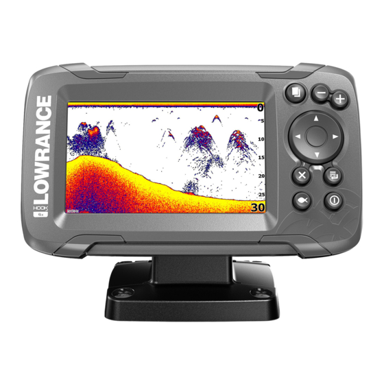
Sonar The Sonar function provides a view of the water and bottom beneath your vessel, allowing you to detect fish and examine the structure of the bottom. The Sonar image Fish arches Data overlay Range limit Bottom Sonar | Hook² X Series Operator Manual... -
Page 20: Zooming The Image
Zooming the image You can zoom the image by using the Zoom keys. Customize the image settings By default the unit is set to Auto mode, and most settings are automated. It is recommended that only experienced sonar users use the customize settings to further customize the image. Select Auto in the menu and change to custom or ice fishing mode to customize image settings. - Page 21 Depth offset All transducers measure water depth from the transducer to the bottom. As a result, water depth readings do not account for the distance from the transducer to the lowest point of the boat (for example; bottom of the keel, rudder, or skeg) in the water or from the transducer to the water surface.
- Page 22 Flasher The Flasher shows a digital flasher sonar view below your transducer. Digital flashers are most commonly used in scenarios such as ice fishing and vertical jigging where the angler does not care as much about the sonar history shown on a traditional sonar view, but is only interested in raw, live sonar returns.
- Page 23 Water column activity (fish, bait fish, etc.) Depth Customize the image settings By default the unit is set to Auto mode, and most settings are automated. It is recommended that only experienced sonar users use the customize settings to further customize the sonar image. Select Auto in the menu and change to custom or ice fishing mode to customize image settings.
-
Page 24: Zooming The Downscan Image
DownScan Ú Note: DownScan is available on 5x and 7x models only. DownScan provides detailed images of structure and fish directly below your boat, down to 91 m (300 ft) at 455 kHz and 46 m (150 ft) at 800 kHz. The DownScan image Data overlay Range limit... - Page 25 Custom mode options When the custom mode is selected the menu expands with more options. Use these menu options to customize the image. DownScan | Hook² X Series Operator Manual...
-
Page 26: Alarm System
Alarms Alarm system The system continuously checks for dangerous situations and system faults while the system is running. When an alarm situation occurs, an alarm message pops up on the screen. If you have enabled the siren, the alarm message is followed by an audible alarm. -
Page 27: Preventive Maintenance
Maintenance Preventive maintenance The unit does not contain any field serviceable components. Therefore, the operator is required to perform only a very limited amount of preventative maintenance. It is recommended that you always fit the protective sun cover when the unit is not in use. Ú...
Need help?
Do you have a question about the HOOK2-4x and is the answer not in the manual?
Questions and answers
Как выйти из режима имитация?
To exit simulation mode on the Lowrance HOOK2-4x, press the on/off button to access the system controls. Then navigate to "Simulator" and turn it off.
This answer is automatically generated
Installing the transducer
To install the transducer for the Lowrance HOOK2-4x, follow these steps:
1. Choose Mounting Location: Decide whether to mount it on the trolling motor, the transom, or inside the hull. Ensure the location allows clear signal and proper water contact.
2. Mounting Bracket: Use the provided mounting bracket. Position it to allow the transducer cable to route through a cable hole or along the boat surface.
3. Clamp or Glue:
- For trolling motor: Use a 2.5 to 4.5-inch expandable clamp to secure the transducer to the motor.
- For shoot-through hull: Apply adhesive to the transducer and the hull surface, press and hold it in place until it adheres. Use sandpaper to clean excess glue and help it stick better.
4. Cable Routing: Run the transducer cable through the bracket and route it cleanly to the control head. Use tie straps to secure it and prevent tangling.
5. Electrical Connection: Connect the power cable to a 12V source. Tuck cables neatly in the battery or electrical panel area. Use grommets or silicone to seal any holes and keep the setup waterproof.
6. Final Check: Ensure all cables are secure, the transducer is firmly mounted, and the display powers on correctly.
This answer is automatically generated
How to make the normal fish finder look like the simulator
To set up the Lowrance HOOK2-4x fish finder to display the simulator view, access the menu system and select the demo or simulator mode. This mode allows the unit to display simulated sonar and GPS data for practice or demonstration.
This answer is automatically generated
Можно ли подключить Гармин и как на монитор
No, the Lowrance HOOK2-4x cannot directly connect to a Garmin monitor. They use different systems and connectors, and are not designed to be interoperable.
This answer is automatically generated
the unit will not come off " SIMULATION" how to eliminate this ? as unit is unusable !!
To disable "SIMULATION" mode on the Lowrance HOOK2-4x, go to the main menu, find the system or settings menu, and look for the option labeled "Simulation" or "Demo Mode." Select it and choose "Off" or "Disable" to turn off simulation mode.
This answer is automatically generated
можно ли купить инструкцию на русском языке
What kind of fuse I need for my Hook 4xgps ?