Table of Contents
Advertisement
Quick Links
Advertisement
Table of Contents

Related Manuals for Jetter JX3-BN-EC

Summary of Contents for Jetter JX3-BN-EC
- Page 1 User Manual JX3-BN-EC We automate your success.
- Page 2 Revisions and further development of our products are not automatically mentioned in a reviewed document. Jetter AG shall not be liable for errors in form or content, or for missing updates, as well as for damages or disadvantages resulting from such failure.
-
Page 3: Table Of Contents
Dismounting the enclosure from the backplane module ............ 17 6 Electrical connection ........................ 18 Improving the noise immunity.................... 19 Ports and interfaces ...................... 20 6.2.1 Terminal X10 - Power supply .................. 20 6.2.1.1 2-pin connector, spring-cage technology............ 20 6.2.2 Ports X14, X15 - EtherCAT®.................. 21 Commissioning........................ 22 JX3-BN-EC User Manual... - Page 4 7.1.1.1 Expansion modules connected with a controller ........... 26 7.1.1.2 Expansion modules connected to an EtherCAT® bus node ...... 27 EtherCAT® object directories.................... 29 7.2.1 Overview ........................ 29 7.2.2 Object Dictionary JX3-BN-EC ................... 29 7.2.3 Object Dictionary JX3-AI4 .................. 33 7.2.4 Object Dictionary JX3-AI4-EI.................. 36 7.2.5 Object Dictionary JX3-AO4 .................. 39...
-
Page 5: Introduction
For information on new revisions of this document, visit the download area on our website. This document is not subject to any updating service. Start | Jetter - We automate your success. For further information refer to the following information products: ■... -
Page 6: Safety
Machinery Directive This device is no safety-related part as per Machinery Directive 2006/42/EC, and must, therefore, not be used for safety-relevant applications. This device is NOT intended for the purpose of personal safety, and must, therefore, not be used to protect persons. JX3-BN-EC User Manual 6 / 92... -
Page 7: Warnings Used In This Document
Low risk CAUTION Indicates a hazardous situation which, if not avoided, could result in minor or moderate injury. Material damage NOTICE Indicates a situation which, if not avoided, could result in malfunctions or material damage. JX3-BN-EC User Manual 7 / 92... -
Page 8: Product Description
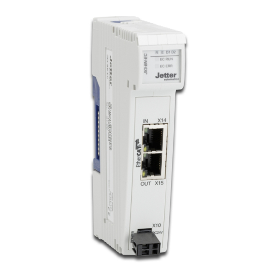
Jetter AG Product description | 3 3 Product description ® The JX3-BN-EC is a bus node that connects JX3 I/O modules with an EtherCAT master. It is used to set up distributed I/O stations. 3.1 Design Fig. 1: Design DIN rail latch... -
Page 9: Status Indication
® 2 flashes Timeout of process data/EtherCAT watchdog ® 1 flash The EtherCAT state was changed indepen- dently by the JX3-BN-EC due to a local error. Blinking General configuration error Flickering Booting error ® EtherCAT communication of the device is... -
Page 10: Nameplate
Serial number Certification mark Item number Hardware revision Item name 3.5 Scope of delivery Scope of delivery Item number Quantity JX3-BN-EC 10001584 Male connector in spring-cage technology, 60870409 2-pin Terminal labels 60870411 Installation manual 60882041 JX3-BN-EC User Manual 10 / 92... -
Page 11: Technical Specifications
Jetter AG Technical specifications | 4 4 Technical specifications This chapter contains information on electrical and mechanical data, as well as on operating data of the JX3-BN-EC. 4.1 Dimensions Fig. 4: Dimensions in mm 4.2 Mechanical specifications Category Description Standards Weight... -
Page 12: Electrical Properties
(ports X14, X15) Electrical Category Description Standards safety Class of protection DIN EN 61131-2 Dielectric test voltage Functional ground is con- nected to chassis ground internally. Protective connection Overvoltage category Tab. 4: Electrical safety JX3-BN-EC User Manual 12 / 92... -
Page 13: Environmental Conditions
Criterion A Discharge through air: 8 kV DIN EN 61131-2 Test peak voltage 8 kV DIN EN 61000-6-2 DIN EN 61000-4-2 Discharge through air 4 kV Test peak voltage Criterion A Tab. 7: Immunity to interference JX3-BN-EC User Manual 13 / 92... -
Page 14: Dc Power Supply Inputs And Outputs
DIN EN 61000-4-5 Surge voltages, asymmetric, line to earth Common-mode interfer- tr/th 1.2/50 µs DIN EN 61131-2 ence DIN EN 61000-6-2 1 kV DIN EN 61000-4-5 Tab. 9: Interference immunity of the DC mains inputs and outputs JX3-BN-EC User Manual 14 / 92... -
Page 15: Mechanical Installation
Jetter AG Mechanical installation | 5 5 Mechanical installation This chapter describes how to install and replace the JX3-BN-EC. 5.1 Installing the device on the DIN rail Functional impairment caused by unfavorable installation NOTICE ► Install the device only in vertical position on the DIN rail (DIN EN 60715). -
Page 16: Removing The Device From The Din Rail
DIN rail release latch Detail view Disconnect the system from the power supply. Remove the device from the mains. Pry the release latch (2) downwards and pull the device off the DIN rail (1). JX3-BN-EC User Manual 16 / 92... -
Page 17: Dismounting The Enclosure From The Backplane Module
Fig. 7: Dismounting the enclosure from the backplane module DIN rail latch Detail view Disconnect the system from the power supply. Press the upper and lower latches (1) on the device simultaneously. Keep the latches pressed and pull off the enclosure. JX3-BN-EC User Manual 17 / 92... -
Page 18: Electrical Connection
Damages to material or functional impairment NOTICE Improper implementation of the wiring harness may cause mechanical stress. ► Protect the cables from bending, twisting or chafing. ► Install strain reliefs for the connecting cables. JX3-BN-EC User Manual 18 / 92... -
Page 19: Improving The Noise Immunity
Note 016 EMC-Compatible Installation of Electric Cabinets on our homepage. DIN rail ■ Mount the JX3-BN-EC on a DIN rail to DIN EN 60715 with the dimensions 35 x 7.5 mm. ■ The DIN rail must be electrically conducting and grounded by either of the two ways: ■... -
Page 20: Ports And Interfaces
Power supply for connected JX3 peripheral modules if they are not supplied by a separate JX3-PS1 power supply module. INFO Design The power supply to the bus node JX3-BN-EC must be designed with a circuit of class 2 according to EN 61131. Pin assignment Description... -
Page 21: Ports X14, X15 - Ethercat
Green Link and activity Yellow No function INFO Topology The EtherCAT® master determines the topology. You can find further information on the topology in the ® EtherCAT® Installation Guideline ETG.1600 of the EtherCAT Technology Group. JX3-BN-EC User Manual 21 / 92... -
Page 22: Commissioning
JX3 peripheral Expansion modules modules Commissioning Carry out the following steps to commission the bus node JX3-BN-EC: ü You need compatible controller and 2 Ethernet patch cables 1:1 or crossover with the following transfer rates: Cat 5e at 10 Mbps to 100 Mbps or Cat 6 at 1.000 Mbps Make sure that the power supply of the controller and the bus node is switched off. - Page 23 Jetter AG Electrical connection | 6 Launch the JetSym software tool. ð Now, you can start configuring the bus node. INFO Further information For more information on this subject, refer to JetSym online help. JX3-BN-EC User Manual 23 / 92...
- Page 24 JX3-sysbus_configurator_xxx_e which is available for download from our Homepage. INFO Connecting third-party hardware You can also use the JX3-BN-EC in combination with a controller that was not developed and produced by der Jetter AG. See also EtherCAT® object directo- ries [} 29].
- Page 25 Jetter AG Programming | 7 System overview ® EtherCAT Fig. 9: System overview JX3-BN-EC ® EtherCAT master with up to 16 JX3 I/O modules Up to 99 JX3-BN-EC JX3-BN-EC User Manual 25 / 92...
- Page 26 I/O number of the module. The I/O numbers always start with the constant prefix 10000. Digits Description value range 10000XXZZ 10000 Prefix Fig. 11: Example: I/O numbers Position of the module in the system 02 … 17 Module-specific I/O number 01 … 16 JX3-BN-EC User Manual 26 / 92...
- Page 27 The ENN is automatically assigned by JetSym. System overview ® EtherCAT Fig. 12: System overview ® EtherCAT bus node with up to ® EtherCAT master 16 JX3 I/O modules ® Up to 99 EtherCAT bus nodes JX3-BN-EC User Manual 27 / 92...
- Page 28 12NN00XXZZ Prefix 1 Fig. 14: Example: I/O numbers Bus node ID, ENN 01 … 99 Prefix 2 Position of the module within the 02 … 33 station Module-specific I/O number 01 … 16 JX3-BN-EC User Manual 28 / 92...
- Page 29 Jetter AG Programming | 7 7.2 EtherCAT® object directories Use with third-party You can also use the JX3-BN-EC in combination with a controller that was not hardware developed and produced by der Jetter AG. ® To establish an EtherCAT connection between the third-party controller and the JX3-BN-EC, you need the object directory of the JX3-BN-EC and the object di- rectories of the connected JX3 I/O modules.
- Page 30 :0x06 Calc and Copy Time UDINT :0x08 Get Cycle Time UINT :0x09 Delay Time UDINT :0x0A Sync0 Cycle Time UDINT :0x0B SM-Event Missed UINT :0x0C Cycle Time Too Small UINT :0x20 Sync Error BOOL JX3-BN-EC User Manual 30 / 92...
- Page 31 UINT :0x04 LED_RUN USINT :0x05 LED_ERROR USINT :0x06 LED_D1 USINT :0x07 LED_D2 USINT 0xFB00 Register interface :0x00 SubIndex 000 USINT :0x01 RegisterNo UDINT :0x02 Write Access BOOL :0x03 Data UDINT Tab. 11: Object dictionary JX3-BN-EC JX3-BN-EC User Manual 31 / 92...
- Page 32 Name 0x1600 RxPDO Map Module 0x1A00 TxPDO Map Module 0x6000 Inputs Module 0x7000 Outputs Module 0x8000 Parameter Module 0xA000 Status Module Example The following JX3 I/O modules are connected to a JX3-BN-EC: Position Module Offset JX3-BN-EC JX3-DIO16 0x00 JX3-AI4 0x10...
- Page 33 :0x12 Input 2.Configuration.UserUI1 UDINT :0x13 Input 2.Configuration.UserDig1 UDINT :0x14 Input 2.Configuration.UserUI2 UDINT :0x15 Input 2.Configuration.UserDig2 UDINT :0x16 Input 2.Configuration.LimitMin UDINT :0x17 Input 2.Configuration.LimitMax UDINT :0x18 Input 2.Configuration.TotalMin UDINT :0x19 Input 2.Configuration.TotalMax UDINT :0x1A Input 2.Configuration.Average UDINT JX3-BN-EC User Manual 33 / 92...
- Page 34 :0x0F Input 3.Common.State UDINT :0x10 Input 3.Common.Value Valid BOOL :0x11 Input 3.Common.Below Lower Limit BOOL :0x12 Input 3.Common.Above Upper Limit BOOL :0x13 Input 3.Common.Out Of Range Negative BOOL :0x14 Input 3.Common.Out Of Range Positive BOOL JX3-BN-EC User Manual 34 / 92...
- Page 35 :0x2B Diagnostics..OS_Version UDINT 0x1600 RxPDO Map Module:JX3-AO4 :0x00 SubIndex 000 USINT :0x01 Output Mapping 1 UDINT :0x02 Output Mapping 2 UDINT :0x03 Output Mapping 3 UDINT :0x04 Output Mapping 4 UDINT Tab. 12: Object Dictionary JX3-AI4 JX3-BN-EC User Manual 35 / 92...
- Page 36 :0x14 Input 2.Configuration.UserUI2 UDINT :0x15 Input 2.Configuration.UserDig2 UDINT :0x16 Input 2.Configuration.LimitMin UDINT :0x17 Input 2.Configuration.LimitMax UDINT :0x18 Input 2.Configuration.TotalMin UDINT :0x19 Input 2.Configuration.TotalMax UDINT :0x1A Input 2.Configuration.Average UDINT :0x1B Input 3.Common.Command UDINT :0x1C Input 3.Common.ForceVal UDINT JX3-BN-EC User Manual 36 / 92...
- Page 37 :0x11 Input 3.Common.Below Lower Limit BOOL :0x12 Input 3.Common.Above Upper Limit BOOL :0x13 Input 3.Common.Out Of Range Negative BOOL :0x14 Input 3.Common.Out Of Range Positive BOOL :0x15 Input 3.Common.Force Value Active BOOL :0x16 Input 4.Common.State UDINT JX3-BN-EC User Manual 37 / 92...
- Page 38 BOOL :0x26 Diagnostics..Out Of Range Positive BOOL :0x27 Diagnostics..Force Value Active BOOL :0x28 Diagnostics..Voltage Monitoring On BOOL :0x29 Diagnostics..Sychronous Data Exchange BOOL :0x2A Diagnostics..Single Sampling Active BOOL :0x2B Diagnostics..OS_Version UDINT Tab. 13: Object Dictionary JX3-AI4-EI JX3-BN-EC User Manual 38 / 92...
- Page 39 :0x13 Output 1.Configuration.TotalMax UDINT :0x14 Output 1.Configuration.CutMin UDINT :0x15 Output 1.Configuration.CutMax UDINT :0x16 Output 2.Common.State UDINT :0x17 Output 2.Common.Writing Error Values BOOL :0x18 Output 2.Common.Below Lower Limit BOOL :0x19 Output 2.Common.Above Upper Limit BOOL JX3-BN-EC User Manual 39 / 92...
- Page 40 :0x40 Output 4.Common.Force Value Active BOOL :0x41 Output 4.Common.Command UDINT :0x42 Output 4.Common.ForceVal UDINT :0x43 Output 4.Common.ErrVal UDINT :0x44 Output 4.Configuration.Config UDINT :0x45 Output 4.Configuration.UserUI1 UDINT :0x46 Output 4.Configuration.UserDig1 UDINT :0x47 Output 4.Configuration.UserUI2 UDINT JX3-BN-EC User Manual 40 / 92...
- Page 41 :0x05 Diagnostics..Error Internal Voltage BOOL :0x06 Diagnostics..Below Lower Limit BOOL :0x07 Diagnostics..Above Upper Limit BOOL :0x08 Diagnostics..Force Value Active BOOL :0x09 Diagnostics..Voltage Monitoring On BOOL :0x0A Diagnostics..Sychronous Data Exchange BOOL :0x0B Diagnostics..OS_Version UDINT Tab. 14: Object Dictionary JX3-AO4 JX3-BN-EC User Manual 41 / 92...
- Page 42 :0x05 Outputs..Output 1 BOOL :0x06 Outputs..Output 2 BOOL :0x07 Outputs..Output 3 BOOL :0x08 Outputs..Output 4 BOOL :0x09 Module..Pointer to process data 1 UDINT :0x0A Module..Pointer to process data 2 UDINT :0x0B multi strobe.command.Command UDINT JX3-BN-EC User Manual 42 / 92...
- Page 43 UDINT :0x31 Counter A..Gate Mask UDINT :0x32 Counter A..Gate IN1 enabled BOOL :0x33 Counter A..Gate IN2 enabled BOOL :0x34 Counter A..Gate IN3 enabled BOOL :0x35 Counter A..Gate IN4 enabled BOOL :0x36 Counter A..GateActiveHigh UDINT JX3-BN-EC User Manual 43 / 92...
- Page 44 :0x52 Counter B..Counter state UDINT :0x53 Counter B..Gate function enabled .8 BOOL :0x54 Counter B..Strobe function enabled .9 BOOL :0x55 Counter B..Search for reference en- BOOL abled .10 :0x56 Counter B..Modulo enabled .14 BOOL JX3-BN-EC User Manual 44 / 92...
- Page 45 Counter B..Strobe IN2 - Falling edge en- BOOL abled :0x79 Counter B..Strobe IN3 - Falling edge en- BOOL abled :0x7A Counter B..Strobe IN4 - Falling edge en- BOOL abled :0x7B Counter B..Reference - Rising edge UDINT JX3-BN-EC User Manual 45 / 92...
- Page 46 Counter C..Trailing pointer - lower limit UDINT :0x9B Counter C..Trailing pointer - upper limit UDINT :0x9C Counter C..Digital filter UDINT :0x9D Counter C..Gate Mask UDINT :0x9E Counter C..Gate IN1 enabled BOOL :0x9F Counter C..Gate IN2 enabled BOOL JX3-BN-EC User Manual 46 / 92...
- Page 47 :0xBB Counter C..Modulo - lower limit UDINT :0xBC Counter C..Modulo - upper limit UDINT :0xBD Counter C..Modulo RPM UDINT :0xBE dual counter 24V..Counter state UDINT :0xBF dual counter 24V..Gate function en- BOOL abled .8 JX3-BN-EC User Manual 47 / 92...
- Page 48 :0xDE dual counter 24V..Gate IN4 is high-active BOOL :0xDF dual counter 24V..Strobe - Rising edge UDINT :0xE0 dual counter 24V..Strobe IN1 - Rising BOOL edge enabled :0xE1 dual counter 24V..Strobe IN2 - Rising BOOL edge enabled JX3-BN-EC User Manual 48 / 92...
- Page 49 :0x01 dual counter 5V..Upper limit exceeded .20 BOOL :0x02 dual counter 5V..Strobe value re- BOOL ceived .24 :0x03 dual counter 5V..Counter blocked by gate BOOL function .25 :0x04 dual counter 5V..Counter enabled .26 BOOL JX3-BN-EC User Manual 49 / 92...
- Page 50 :0x24 dual counter 5V..Reference Mask UDINT :0x25 dual counter 5V..Reference IN1 enabled BOOL :0x26 dual counter 5V..Reference IN2 enabled BOOL :0x27 dual counter 5V..Reference IN3 enabled BOOL :0x28 dual counter 5V..Reference IN4 enabled BOOL JX3-BN-EC User Manual 50 / 92...
- Page 51 :0x0D Inputs..Input 2 BOOL :0x0E Inputs..Input 3 BOOL :0x0F Inputs..Input 4 BOOL :0x10 Version..OS version UDINT :0x11 Version..FPGA version UDINT :0x12 Version..BL version UDINT :0x13 Version..FPGA version - counter features UDINT :0x14 multi strobe.command.State UDINT JX3-BN-EC User Manual 51 / 92...
- Page 52 :0x2D SimpleCAM..Out 3: 1 = valid data BOOL :0x2E SimpleCAM..Out 4: 1 = valid data BOOL :0x2F SimpleCAM..Bit 6 = 1 Counter-control en- BOOL abled :0x30 SimpleCAM..Bit 7 = 1 Error occurred BOOL :0x31 Counter A..Period UDINT JX3-BN-EC User Manual 52 / 92...
- Page 53 UDINT :0x36 Counter C..Pulse width UDINT :0x37 dual counter 24V..Strobe UDINT :0x38 dual counter 24V..Period UDINT :0x39 dual counter 5V..Strobe UDINT :0x3A dual counter 5V..Period UDINT :0x3B SSI..Count value UDINT Tab. 15: Object Dictionary JX3-CNT JX3-BN-EC User Manual 53 / 92...
- Page 54 :0x0E DI 13 BOOL :0x0F DI 14 BOOL :0x10 DI 15 BOOL :0x11 DI 16 BOOL 0x8000 Parameter Module:JX3-DI16 :0x00 SubIndex 000 USINT :0x01 Diagnostics..Status UDINT :0x02 Pulse Stretching with Digital Inputs..En- UDINT able JX3-BN-EC User Manual 54 / 92...
- Page 55 :0x19 Digital Input Filters..Digital filter for IN 12 BOOL is active :0x1A Digital Input Filters..Digital filter for IN 13 BOOL is active :0x1B Digital Input Filters..Digital filter for IN 14 BOOL is active JX3-BN-EC User Manual 55 / 92...
- Page 56 :0x03 Diagnostics..Voltage at terminal X21.DC BOOL 24 V is below 16.3 V :0x04 Diagnostics..Voltage at terminal X32.DC BOOL 24 V is below 16.3 V :0x05 Diagnostics..Firmware Version UDINT Tab. 16: Object Dictionary JX3-DI16 JX3-BN-EC User Manual 56 / 92...
- Page 57 UDINT :0x0F Input Mapping 14 UDINT :0x10 Input Mapping 15 UDINT :0x11 Input Mapping 16 UDINT 0x6000 Inputs Module:JX3-DIO16 :0x00 SubIndex 000 USINT :0x01 State DINT :0x02 DI 1 BOOL :0x03 DI 2 BOOL JX3-BN-EC User Manual 57 / 92...
- Page 58 :0x0F Digital Input Filters..Digital filter for IN 2 is BOOL active :0x10 Digital Input Filters..Digital filter for IN 3 is BOOL active :0x11 Digital Input Filters..Digital filter for IN 4 is BOOL active JX3-BN-EC User Manual 58 / 92...
- Page 59 OUT 12 is set in case of interruption :0x2F Error conditions Digital Outputs..Output BOOL OUT 13 is set in case of interruption :0x30 Error conditions Digital Outputs..Output BOOL OUT 14 is set in case of interruption JX3-BN-EC User Manual 59 / 92...
- Page 60 :0x00 SubIndex 000 USINT :0x01 Counter A..State UDINT :0x02 Counter A..Overflow BOOL :0x03 Counter A..Counter UDINT :0x04 Counter B..State UDINT :0x05 Counter B..Overflow BOOL :0x06 Counter B..Counter UDINT :0x07 Error conditions Digital outputs..State UDINT JX3-BN-EC User Manual 60 / 92...
- Page 61 BOOL output driver :0x12 Diagnostics..Voltage at terminal X21.DC BOOL 24 V is below 16.3 V :0x13 Diagnostics..Voltage at terminal X32.DC BOOL 24 V is below 16.3 V :0x14 Diagnostics..Version UDINT Tab. 17: Object Dictionary JX3-DIO16 JX3-BN-EC User Manual 61 / 92...
- Page 62 BOOL :0x0E DO 14 BOOL :0x0F DO 15 BOOL :0x10 DO 16 BOOL 0x1A00 TxPDO Map Module:JX3-DO16 :0x00 SubIndex 000 USINT :0x01 State UDINT 0x6000 Inputs Module:JX3-DO16 :0x00 SubIndex 000 USINT :0x01 State DINT JX3-BN-EC User Manual 62 / 92...
- Page 63 OUT 3 is set in case of interruption :0x19 Error conditions Digital Outputs..Output BOOL OUT 4 is set in case of interruption :0x1A Error conditions Digital Outputs..Output BOOL OUT 5 is set in case of interruption JX3-BN-EC User Manual 63 / 92...
- Page 64 OUT 10 is set in case of interruption :0x0C Error conditions Digital Outputs..Output BOOL OUT 11 is set in case of interruption :0x0D Error conditions Digital Outputs..Output BOOL OUT 12 is set in case of interruption JX3-BN-EC User Manual 64 / 92...
- Page 65 BOOL output driver :0x14 Diagnostics..Voltage at terminal X21.DC BOOL 24 V is below 16.3 V :0x15 Diagnostics..Voltage at terminal X32.DC BOOL 24 V is below 16.3 V :0x16 Diagnostics..Version UDINT Tab. 18: Object Dictionary JX3-DO16 JX3-BN-EC User Manual 65 / 92...
- Page 66 :0x12 Channel 2.Common.ForceVal UDINT :0x13 Channel 2.Configuration.Average UDINT :0x14 Channel 2.Configuration.LimitMin UDINT :0x15 Channel 2.Configuration.LimitMax UDINT :0x16 Channel 2.Configuration.Sensor Sensitiv- UDINT ity - replaced by 1234 :0x17 Channel 2.Configuration.TotalMin UDINT :0x18 Channel 2.Configuration.TotalMax UDINT JX3-BN-EC User Manual 66 / 92...
- Page 67 :0x0F Channel 1.Diagnostics.Veryfast mode ac- BOOL tive :0x10 Channel 1.Diagnostics.Fast mode active BOOL :0x11 Channel 1.Diagnostics.Slow mode active BOOL :0x12 Channel 1.Diagnostics.Calibration data BOOL active :0x13 Channel 1.Diagnostics.Forcemode active BOOL :0x14 Channel 1.Diagnostics.Very slow mode BOOL active JX3-BN-EC User Manual 67 / 92...
- Page 68 :0x25 Channel 2.Diagnostics.Scaling active BOOL :0x26 Channel 2.Diagnostics.User calibration 1 BOOL done :0x27 Channel 2.Diagnostics.User calibration 2 BOOL done :0x28 Channel 2.Diagnostics.Channel 2 active BOOL :0x29 Channel 2.Diagnostics.Voltage down BOOL Tab. 19: Object Dictionary JX3-DMS2 JX3-BN-EC User Manual 68 / 92...
- Page 69 :0x0C Input Mapping 11 UDINT 0x6000 Inputs Module:JX3-MIX1 :0x00 SubIndex 000 USINT :0x01 State DINT :0x02 PDI 1 DINT :0x03 PDI 2 DINT :0x04 PDI 3 DINT :0x05 DI 1 BOOL :0x06 DI 2 BOOL JX3-BN-EC User Manual 69 / 92...
- Page 70 Status Module:JX3-MIX1 :0x00 SubIndex 000 USINT :0x01 Inputs..All Inputs UDINT :0x02 Digital Inputs..All Inputs UDINT :0x03 Digital Inputs..Input 1 BOOL :0x04 Digital Inputs..Input 2 BOOL :0x05 Digital Inputs..Input 3 BOOL :0x06 Digital Inputs..Input 4 BOOL JX3-BN-EC User Manual 70 / 92...
- Page 71 :0x2F counter B..force activated BOOL :0x30 counter B..modulo function activated BOOL :0x31 counter B..gate function activated BOOL :0x32 counter B..strobe function activated BOOL :0x33 counter B..reset function activated BOOL :0x34 counter B..count direction positive BOOL JX3-BN-EC User Manual 71 / 92...
- Page 72 :0x57 Diagnostics..stepper motor: axis busy BOOL :0x58 Diagnostics..stepper motor: decceleration BOOL activated :0x59 Diagnostics..analog I/O: data valid BOOL :0x5A Diagnostics..serial interface: data received BOOL :0x5B Diagnostics..synchronous data exchange BOOL :0x5C Diagnostics..OS_Version UDINT Tab. 20: Object Dictionary JX3-MIX1 JX3-BN-EC User Manual 72 / 92...
- Page 73 :0x02 Outputs..All Outputs UDINT :0x03 Digital Outputs..All Outputs UDINT :0x04 Digital Outputs..Output 1 BOOL :0x05 Digital Outputs..Output 2 BOOL :0x06 Digital Outputs..Output 3 BOOL :0x07 Digital Outputs..Output 4 BOOL :0x08 analog input 1..command UDINT JX3-BN-EC User Manual 73 / 92...
- Page 74 :0x0D analog input 2..state UDINT :0x0E analog input 2..error calibration values BOOL :0x0F analog input 2..error analog submodule BOOL :0x10 analog input 2..analog data valid BOOL :0x11 analog input 3..value UDINT :0x12 analog input 3..state UDINT JX3-BN-EC User Manual 74 / 92...
- Page 75 BOOL :0x39 serial interface..frame error BOOL :0x3A serial interface..data received BOOL :0x3B serial interface..send buffer filling level UDINT :0x3C serial interface..receive buffer show UDINT :0x3D serial interface..receive buffer level UDINT :0x3E stepper motor..state UDINT JX3-BN-EC User Manual 75 / 92...
- Page 76 :0x5D Diagnostics..stepper motor: axis busy BOOL :0x5E Diagnostics..stepper motor: decceleration BOOL activated :0x5F Diagnostics..analog I/O: data valid BOOL :0x60 Diagnostics..serial interface: data received BOOL :0x61 Diagnostics..synchronous data exchange BOOL :0x62 Diagnostics..OS_Version UDINT Tab. 21: Object Dictionary JX3-MIX2 JX3-BN-EC User Manual 76 / 92...
- Page 77 :0x05 Channel 1.Common.4-wire measuring ac- BOOL tive :0x06 Channel 1.Common.10 ms Conversion BOOL active (0=100ms) :0x07 Channel 1.Common.Value Valid BOOL :0x08 Channel 1.Common.Channel is calibrated BOOL :0x09 Channel 1.Common.Forceval is shown BOOL :0x0A Channel 1.Common.PT100 active BOOL (0=PT1000) JX3-BN-EC User Manual 77 / 92...
- Page 78 :0x28 Diagnostics..ErROr Adjust Values BOOL :0x29 Diagnostics..All Chanels Valid BOOL :0x2A Diagnostics..Cable Break BOOL :0x2B Diagnostics..Short-Circuit BOOL :0x2C Diagnostics..Below Lower Limit BOOL :0x2D Diagnostics..Above Upper Limit BOOL :0x2E Diagnostics..One value measured BOOL :0x2F Diagnostics..Force Value Active BOOL JX3-BN-EC User Manual 78 / 92...
- Page 79 Jetter AG Programming | 7 Sub- Type Description/ Index Type of ac- Name cess 0xA000 :0x30 Diagnostics..SychROnous Data Exchange BOOL :0x31 Diagnostics..OS_Version UDINT Tab. 22: Object Dictionary JX3-THI2-RTD JX3-BN-EC User Manual 79 / 92...
- Page 80 :0x05 Channel 1.Common.4-wire measuring ac- BOOL tive :0x06 Channel 1.Common.10 ms Conversion BOOL active (0=100ms) :0x07 Channel 1.Common.Value Valid BOOL :0x08 Channel 1.Common.Channel is calibrated BOOL :0x09 Channel 1.Common.Forceval is shown BOOL :0x0A Channel 1.Common.PT100 active BOOL (0=PT1000) JX3-BN-EC User Manual 80 / 92...
- Page 81 :0x28 Diagnostics..Error Adjust Values BOOL :0x29 Diagnostics..All Chanels Valid BOOL :0x2A Diagnostics..Cable Break BOOL :0x2B Diagnostics..Short-Circuit BOOL :0x2C Diagnostics..Below Lower Limit BOOL :0x2D Diagnostics..Above Upper Limit BOOL :0x2E Diagnostics..One value measured BOOL :0x2F Diagnostics..Force Value Active BOOL JX3-BN-EC User Manual 81 / 92...
- Page 82 Jetter AG Programming | 7 Sub- Type Description/ Index Type of ac- Name cess 0xA000 :0x30 Diagnostics..Sychronous Data Exchange BOOL :0x31 Diagnostics..OS_Version UDINT Tab. 23: Object Dictionary JX3-THI2-RTD-EI JX3-BN-EC User Manual 82 / 92...
- Page 83 :0x05 Channel 1.Common.Value Valid BOOL :0x06 Channel 1.Common.Channel is calibrated BOOL :0x07 Channel 1.Common.Forcing enabled BOOL :0x08 Channel 1.Common.show temperature of BOOL thermocouple (0= show temperature of icepoint) :0x09 Channel 1.Common.temperature is shown BOOL (0=Voltage of thermocouple) JX3-BN-EC User Manual 83 / 92...
- Page 84 :0x1C Diagnostics..Cable Break BOOL :0x1D Diagnostics..Short-Circuit BOOL :0x1E Diagnostics..Below Lower Limit BOOL :0x1F Diagnostics..Above Upper Limit BOOL :0x20 Diagnostics..Force Value Active BOOL :0x21 Diagnostics..Sychronous Data Exchange BOOL :0x22 Diagnostics..OS_Version UDINT Tab. 24: Object Dictionary JX3-THI2-TC JX3-BN-EC User Manual 84 / 92...
- Page 85 :0x05 Channel 1.Common.Value Valid BOOL :0x06 Channel 1.Common.Channel is calibrated BOOL :0x07 Channel 1.Common.Forcing enabled BOOL :0x08 Channel 1.Common.show temperature of BOOL thermocouple (0= show temperature of icepoint) :0x09 Channel 1.Common.temperature is shown BOOL (0=Voltage of thermocouple) JX3-BN-EC User Manual 85 / 92...
- Page 86 :0x1C Diagnostics..Cable Break BOOL :0x1D Diagnostics..Short-Circuit BOOL :0x1E Diagnostics..Below Lower Limit BOOL :0x1F Diagnostics..Above Upper Limit BOOL :0x20 Diagnostics..Force Value Active BOOL :0x21 Diagnostics..Sychronous Data Exchange BOOL :0x22 Diagnostics..OS_Version UDINT Tab. 25: Object Dictionary JX3-THI2-TC-EI JX3-BN-EC User Manual 86 / 92...
- Page 87 Pay attention to the feedback from the status display [} 9] of the JX3-BN-EC while performing an operating system update. ü The latest OS file for the JX3-BN-EC has been downloaded from the Jetter homepage. ü Controller and JetSym are connected. ü...
- Page 88 PDOs or module registers ■ In the JetSym oscilloscope, do not use the internal mode but the live mode. JX3-BN-EC User Manual 88 / 92...
- Page 89 In case of damaged packaging inspect the device for any visible damage, and in- form your freight forwarder and the Jetter AG of the damage caused during ship- ment. If the device is damaged or has been dropped, it is strictly forbidden to use...
- Page 90 To contact them, please call our technical hotline or use the contact form on our homepage: Technical hotline | Jetter - We automate your success. You are also welcome to send an e-mail to our technical hotline: hotline@jetter.de...
- Page 91 Male connector in spring-cage technology, 2-pin 60870409 Tab. 26: Spare parts 11.2 Accessories INFO The accessories are not part of the scope of delivery. Apt accessories can be obtained from Jetter AG. Component Item number Screwdriver 60871712 End clamp for DIN rail 60863970 Tab. 27: Accessories...
- Page 92 Jetter AG Graeterstrasse 2 71642 Ludwigsburg www.jetter.de E-mail info@jetter.de Phone +49 7141 2550-0 We automate your success.
Need help?
Do you have a question about the JX3-BN-EC and is the answer not in the manual?
Questions and answers