Table of Contents
Advertisement
Quick Links
http://www.narda-sts.it
PMM ER8000
User's Manual
9 kHz ÷ 30 MHz (option 00)
9 kHz ÷ 3000 MHz (option 01)
SERIAL NUMBER OF THE INSTRUMENT
You can find the Serial Number on the rear panel of the instrument.
Serial Number is in the form: 0000X00000.
The first four digits and the letter are the Serial Number prefix, the last five digits are
the Serial Number suffix. The prefix is the same for identical instruments, it changes
only when a configuration change is made to the instrument.
The suffix is different for each instrument.
Document ER8000EN-01101-1.00 - Copyright © NARDA 2020
Sales & Support:
NARDA
Via Rimini, 22
Safety
20142 - Milano (MI)
Test
Tel.: +39 02 581881
Solutions
Fax: +39 02 58188273
S.r.l. Socio Unico
EMI RECEIVER
Manufacturing Plant:
Via Benessea, 29/B
17035 - Cisano sul Neva (SV)
Tel.: +39 0182 58641
Fax: +39 0182 586400
Advertisement
Table of Contents

Summary of Contents for L3Harris NARDA PMM ER8000
- Page 1 Sales & Support: Manufacturing Plant: NARDA Via Rimini, 22 Via Benessea, 29/B Safety 20142 - Milano (MI) 17035 - Cisano sul Neva (SV) Test Tel.: +39 0182 58641 Tel.: +39 02 581881 Solutions Fax: +39 0182 586400 Fax: +39 02 58188273 S.r.l.
- Page 2 NOTE: ® Names and Logo are registered trademarks of Narda Safety Test Solutions GmbH and L3Harris Communications Holdings, Inc. – Trade names are trademarks of the owners. If the instrument is used in any other way than as described in this User’s Manual, it may become unsafe.
-
Page 3: Front Panel
Contents Page Explanation of electrical and safety symbols……..…………………………… General safety considerations and instructions.………..……………………. PMM ER8000 EC Declaration of Conformity ....……………………… VIII 1. General Information Page 1.1 Documentation………………………………………………………………………. 1.2 Operating Manual changes………………………………………………………… 1.3 Introduction to PMM ER8000……………………………………………………… 1.4 Instrument Items………….………………………………………………………… 1.5 Optional accessories……………….………………………………………………. 1.6 Other accessories…………………………………………………………………. - Page 4 3 Operating Instructions Page 3.1 Introduction…………………………………………………………………….. 3.2 Operating Modes .…………………………………………………………….. 3.2.1 Sweep Mode..………………………………………………………………… 3.2.2 Analyzer Mode ………………………………………………………………. 3.2.3 Manual Mode ………………………………………………………………… 3.3 Detectors ………………………………………………………………………… 3.3.1 RMS-AVG Definition …………………………………………………………. 3.3.2 C-AVG Definition …………………………………………………………….. 3.3.3 Smart Detector ………………………………………………………………. 3.4 RBW Filters …………………………………………………………………..… 3.4.1 MIL Filters …………………………………………………………………….
- Page 5 6 PMM 9010-RMA Rack Mount Adapter for Rack 19” Page 6.1 Introduction ..……….…………………………………………………….. 6.2 Instruments Items ..…………………………...………………………… 6.3 PMM 9010-RMA Main Specifications………………………………… 6.4 PMM 9010-RMA Front view………………………………...…………. 6.5 PMM 9010-RMA Inside view…………………………..…...…………. 6.6 Rack requirements……………..……….…………………...…………. 6.7 Required equipment…………………..………………..…...…………. 6.8 Moving chassis……………….……………..…………………………… 6.9 Installation guidelines …………………………………………………..
-
Page 6: Table Of Contents
Figures Figure Page Front Panel …………………………………………………………….…. Rear Panel …………………………………………………………..PMM ER8000 Functional Block Diagram…………………………….… PMM L2-16A remote cable configuration for ER8000………………... PMM LISN three phase remote cable configuration for ER8000..PMM L3-25 remote cable configuration for PMM ER8000 ………..… Schwarzbeck Model HXYZ 9170 Triple Loop Antenna Cable …..….. AMN Principle: a) ∆-type or T-type LISN ;... - Page 7 SAFETY RECOMMENDATIONS AND INSTRUCTIONS This unit has been designed and tested in Italy, according to IEC 348 standard and has left the manufacturer’s premises in a state fully complying with the safety standards ; in order to maintain the unit in a safe state and to ensure safe operation, the following instructions must be reviewed and fully understood before operation.
- Page 8 Dichiarazione di Conformità EC Declaration of Conformity In accordo alla Decisione 768/2008/EC, conforme alle direttive EMC 2014/30/UE, Bassa Tensione 2014/35/UE e RoHS 2011/65/UE, ed anche alle norme ISO/IEC 17050-1 e 17050-2. In accordance with the Decision 768/2008/EC, compliant to the Directives EMC 2014/30/UE, Low Voltage 2014/35/UE and RoHS 2011/65/EU, also compliant to the ISO/IEC standard 17050-1 and 17050-2 Il costruttore narda...
- Page 9 1 – General Information Enclosed with this manual are: 1.1 Documentation • a service questionnaire to send back to NARDA in case an equipment service is needed • an accessories checklist to verify all accessories enclosed in the packaging. Instruments manufactured after the printing of this manual may have a 1.2 Operating serial number prefix not listed on the title page;...
- Page 10 PMM ER8000 includes the following items: 1.4 Instrument • EMI Receiver from 10 Hz up to 30 MHz (opt.00) or 10 Hz to 3000 MHz (opt.01) Items • Soft carrying case • AC/DC Converter with plug adapters; • LISN Mains Cable •...
- Page 11 Table 1-1 lists the PMM ER8000 performance specifications. 1.7 Main Specifications The following conditions apply to all specifications: • The ambient temperature shall be -5°C to 45°C TABLE 1-1 Main Specifications Frequency Range 9 kHz to 30 MHz (Opt. 00) 9 kHz to 3 GHz (Opt.
- Page 12 Scan time SWEEP MODE ANALYZER MODE (CISPR: preselector ON, QP detector) (preselector OFF, Peak detector, Hold time lowest) < 2 s (Hold time 1 s) < 50 ms (Ht 27 ms) A band (9 kHz to 150 kHz) < 3 s (Hold time 2 s) 200 Hz RBW <...
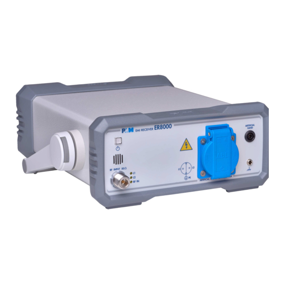
- Page 13 1.8 Front Panel Fig. 1-1 Front Panel Legend from left to right: : Switch ON pushbutton with integrated red/green LED which indicates the power status - Grid: Speaker grid - RF Input connector: Receiver Input - LEDs: L1, L2 LISN lines and RF Input indications - AMN: Artificial Mains Network: EUT Socket - Artificial Hand: Standard 4 mm socket - Earth ground connector...
- Page 14 1.9 Rear Panel Fig. 1-2 Rear Panel Legend from left to right: - Product Label and Serial Number - Mains socket to connect the EUT to the mains through the internal LISN. - Product Label and Serial Number - LISN OUT LISN RF Output, BNC connector Cooling Fan controlled by firmware Power Supply...
-
Page 15: Pmm Er8000 Functional Block Diagram
1.10 Functional The PMM ER8000 features a completely new receiver architecture based on the most recent DSP and FPGA technology, as shown on the diagram Description below. Fig. 1-3 PMM ER8000 Functional BLOCK Diagram The input stage integrates a switch system able to select the signal source coming from the N panel connector or from the desired line of the internal LISN. - Page 16 In the CISPR bands A (9 kHz ÷ 150 kHz), B (150 kHz ÷ 30 MHz), C (30 ÷ 1.11 Ultra fast 300 MHz) and D (300 ÷ 1000 MHz) the standards requires the use of measurement: a specially shaped 200 Hz, 9 kHz, and 120 kHz RBW filters. unique feature of For example, in the CISPR band A (9 ÷...
- Page 17 All electric and electronic devices are potential generators of Electro- 1.12 Emission Magnetic Interference (EMI). measurements The term EMI thus refers to the electromagnetic energy emitted by a device which propagates itself along cables or through the air and couples with other devices that are present in the surroundings.
- Page 18 Differently from PMM 9010, which is a digital sweeping receiver based on 1.13 Principle of a zero-lock-time, step-by-step NCO (numeric controlled oscillator), fast operation settling time FIR RBW filters followed by digital detectors - something faster than conventional receivers anyway - the ER8000 is a real-time gapless receiver based on FFT (Fast Fourier Transform) which evaluates N frequencies in a single shot.
- Page 19 2 - Installation This section provides the information needed to install your PMM ER8000. 2.1 Introduction It includes the information pertinent to initial inspection and power requirements, connections, operating environment, instrument mounting, cleaning, storage and shipment. 2.2 Initial Inspection When receiving the equipment, first inspect the shipping cardbox for any damages.
- Page 20 To switch the unit ON, press the square button and keep it pressed till the 2.5.2 Switch ON led lights up, then release the button; the boot sequence takes place pushbutton with automatically. integrated led When the led inside the button becomes green, the instrument is ready for use.
- Page 21 If the instrument should be returned to NARDA for service, please complete 2.7 Return for Service the service questionnaire enclosed with the Operating Manual and attach it to the instrument. To minimize the repair time, be as specific as possible when describing the failure.
- Page 22 When using a PMM LISN, it is possible to control from the receiver the lines of the LISN and automatically switch between them connecting a special cable between the User Port of the receiver and the LISN remote control input. Push and keep pressed the “ON/OFF”...
- Page 23 When a LISN cannot be used – e.g. when measurements have to be made 2.13 Using Current and on terminals other than the mains ones, such as load or command Voltage Probes terminals, sensitive to inserted capacities for example, or when LISNs of adequate current capabilities aren’t available, or when the line voltage is too high –...
- Page 24 The following figure shows the LISN remote cable pin configuration. This 2.16 PMM L2-16A cable is normally provided in L2-16A package, alternatively it can be Remote Cable requested to N or arranged locally. arda configuration for PMM ER8000 The PMM L2-16A is no longer supported. Please, check the manufacturing status of the Narda products from the website at http://www.narda-sts.it or contact your Narda –...
- Page 25 The following figure shows the LISN remote cable pin configuration. The 2.17 PMM LISNs cable can be requested to N or arranged locally. Three Phase arda Remote Cable configuration for PMM ER8000 (L3-25 excluded) Fig. 2-2 PMM LISN three phase remote cable configuration for PMM ER8000 Installation...
- Page 26 The following figure shows the LISN remote cable pin configuration. The 2.18 PMM L3-25 cable can be requested to N or arranged locally. Remote Cable arda configuration The PMM L3-25 is no longer supported. Please, check the for PMM ER8000 manufacturing status of the Narda products from the website at http://www.narda-sts.it or contact your Narda –...
- Page 27 The following figure shows the HXYZ 9170 Triple Loop Antenna remote 2.19 Schwarzbeck Model cable pin configuration. This cable can be requested to Narda or arranged HXYZ 9170 Triple locally. Loop Antenna Remote Cable configuration for PMM 7010 Fig. 2-4 HXYZ 9170 remote cable configuration for PMM ER8000 Installation...
- Page 28 This page has been left blank intentionally 2-10 Installation...
- Page 29 3 – Operating Instructions 3.1 Introduction The PMM ER8000 EMI Receiver needs to be driven by a PC through an USB connection. The system is provided with a specifically developed software called PMM Emission Suite, which installer utility is stored on the Software Media shipped together with the instrument.
- Page 30 The purpose of this operating mode is to make an easy and fast debugging 3.2.2 ANALYZER tool available to the User. MODE To enter the ANALYZER Mode it’s enough to depress the Analyzer soft key on the main screen. In this mode the receiver works as a powerful Spectrum Analyzer and the display shows the "spectrum analysis"...
- Page 31 PMM ER8000 has been designed to allow the use of many kinds of detectors. 3.3 Detectors CISPR Standard has introduced the application of two detectors that are derived from the Root Mean Squared and from the Average ones. The RMS-Average detector is a special function, defined by the CISPR 3.3.1 RMS-AVG standard, implemented in the PMM ER8000 receiver.
- Page 32 3.3.3 Smart The Smart Detector is a special function implemented in the PMM ER8000 Detector receiver with the purpose of reducing the test time and increasing the productivity of the lab. This function works only in the C, D and E bands when at least one limit is loaded, therefore remember to enable a limit to run the Smart detector function.
- Page 33 With the Peak, RMS and AVG detectors the smallest settable measurement time depends on the RBW. If several detectors are used contemporarily the Hold Time should be set to meet the requirement of the slowest one, so that the results of the measurement are correct for all them.
- Page 34 The Hold Time (expressed in milliseconds) represents the time the receiver 3.5 Hold Time uses to “take a snapshot” of the incoming signal and to measure it with the chosen detector. When selecting a detector, the default hold time value is automatically loaded, but in some cases this time is not appropriate, e.g.
- Page 35 4 – Applications ElectroMagnetic Interference (EMI) voltage measurements on power supply 4.1 Measuring the lines or on signal lines are carried out by means of "Coupling Networks" EMI Voltage (e.g. LISNs) or other transducers (e.g. voltage probes). The frequency range is dictated by the applicable standard, however it is generally limited from 9 kHz to 30 MHz in commercial applications, while for measurements on other equipment/accessories - e.g.
-
Page 36: Amn Principle: A) ∆-Type Or T-Type Lisn ; B) V-Type Lisn
V-LISN test 250 µ H 50 µ H 0.25 µ F mains receiver mains 50 Ω 2 µ F 8 µ F 5 Ω lowpass highpass filter filter V-LISN (only one line is shown) test receiver RF load to interference asym asym unsym... - Page 37 Current Probes may be Clamp-on Probes or Fixed-ring Probes. 4.1.2.2 Current Probe Current Probes are used to measure differential or common mode RFI currents. In some cases it may be important to make a distinction between the two kinds of current flowing in a system. RFI current measurements with Current Probes may be required, for example, when measuring EMI from shielded lines or from complex wiring systems, when finding interference sources among other sources in a...
-
Page 38: Er8000 Internal Lisn
Fig. 4-2 ER8000 internal LISN Fig. 4-3 ER8000 with external L2-16B LISN Applications... - Page 39 A step-by-step example of a conducted test is the following: 4.1.4 Guidance on a 1. Connect the EUT to the front panel socket and the mains network to the preliminary rear plug trough a proper isolation transformer. Leave the EUT switched Measuring off;...
- Page 40 This page has been left blank intentionally Applications...
- Page 41 5 – Updating firmware The PMM ER8000 features a simple and user-friendly method for updating 5.1 Introduction its internal firmware through a Personal Computer (PC). This section provides all the information required for easy updating. The following procedure works both for the ER8000/00 and ER8000/01 options.
- Page 42 Click on “ER8000SeriesUp” (ER8000SeriesUp.exe) once for running the update program, so getting the following window: Two firmware components can be updated by this application: Firmware, which is the receiver internal program, and FPGA, to update the internal programmable logic. ER8000FW.ldr file required Firmware...
- Page 43 The program will display the following window: 5.5 To transfer data To start the process simply switch PMM ER8000 on, select Update Firmware or Update FPGA button, and wait until the automatic transfer is completed. During the firmware storing procedure, a blue bar will progress from left to right in the window of the PC, showing percentage of downloading time by time until 100%.
- Page 44 In the meanwhile on the ER8000 front panel the DATA RX and TX led will blink to indicate a serial communication is going on. When FW download finishes, following message appears to show that everything was properly completed: The length of the file can change with the version. In case of failure, an error message is showed instead.
- Page 45 6 – PMM 9010-RMA Rack Mount Adapter for Rack 19” (Option) 6.1 Introduction A 19-inch rack is a standardized frame or enclosure for mounting multiple equipment modules. Equipment designed to be placed in a rack is typically described as rack-mount or simply chassis; the height of the electronic modules is standardized as multiples of 1.75 inches (44.5 mm) or one rack unit or "U".
- Page 46 Table 6-1 lists the PMM 9010-RMA specifications. 6.3 PMM 9010-RMA Main Specifications TABLE 6-1 Technical Specifications -5° to 45°C Environment temperature Rack unit Dimensions 483 x 410 x 132,5 mm (WxDxH) 5,5 Kg (without instruments) Weight 6.4 PMM 9010-RMA Front view Fig.
- Page 47 6.5 PMM 9010-RMA Inside view Fig. 6-2 Inside view Legend:: 1 – Round holes of service 2 – Rectangular holes used to put ER8000 Instrument; 3 – ER8000 straps; 4 – Rectangular holes for future implementation; 5 – Straps for future implementation. PMM 9010-RMA Rack Mount Adapter...
- Page 48 The rack must be of the following type: 6.6 Rack Requirements - Standard 19 inch (483 mm) with mounting rails that conform to English universal hole spacing per section 1 of ANSI/EIA-310-D-1992. - The minimum vertical rack space per chassis must be 3U (rack units), equal to 3 inches (132,5 mm).
- Page 49 When installing the chassis, follow these guidelines: 6.9 Installation guidelines - Plan your site configuration and prepare the site before installing the chassis. - Ensure that there is adequate space around the rack to allow for servicing the chassis and for airflow. - If the rack has wheels, ensure that the brakes are engaged or that the rack is otherwise stabilized - For a round hole (tapped) rack, use clip nuts with M6 x 16 screw...
- Page 50 This section describes how to install the PMM 9010-RMA Rack Mount Adapter: 6.10 Installing the PMM 9010-RMA - Insert the cage nuts behind the vertical rails with respect to the Rack Unit Boundary and the distance show below: - Y ou can use a rack-insertion tool or a flat-blade screwdriver to install the cage nuts.
-
Page 51: Pmm 9010-Rma With Er8000 Instrument
6.11 Use of the The following procedure is indifferently referred to the ER8000/00 or PMM 9010-RMA ER8000/01. with PMM ER8000 This section provides the information needed to install your ER8000 Instrument on the PMM 9010-RMA Rack Mount Adapter. - Remove the frontal panel from the Rack unscrewing the milled knob without loosing it completely. - Page 52 This page has been left blank intentionally PMM 9010-RMA Rack Mount Adapter...
- Page 53 7 – Remote control PMM ER8000 has been designed to allow remote control operations 7.1 Introduction through its USB (Rear) port. A RS232 serial port is also provided for service activities. Half duplex communication is implemented. The RS232 port has a DB-9 7.2 Communication female connector and the USB 2.0 has a USB-B connector.
- Page 54 7.5 List of commands Query COMMANDs Syntax Function Tells whether the apparatus is a PMM ER8000 and in which mode ?3PR* ?AAT* Requests the Attenuator status for Analyzer mode. Requests the Center frequency for analyzer mode ?ACE* ?ADT* Requests the detector used for Analyzer mode Requests the Hold Time for Analyzer mode.
- Page 55 Setting COMMANDs Syntax Function Aborts a sweep currently in progress ASBK Suspends a sweep currently in progress ASPA Resumes a sweep previously paused ASRE S3PRC Sets the input for bands A, B Sets the input for bands C, D and E S3PRR SAAT a Sets Attenuator for Analyzer Mode...
- Page 56 Following are Commands to control and set various operating modes of PMM 7.6 PMM ER8000 ER8000, that can be distinguished in two main groups: COMMANDs • Query Commands • Setting Commands 7.6.1 Query Description COMMANDs ?3PR This query command #?3PR * sends back a string expressing whether the apparatus is a PMM ER8000 and in which mode.
- Page 57 ?CFA This query command #?CFA* sends back a string in the format CFA=n,(LABEL) where n is the ID of the conversion factor as shown in ER8000 menu and LABEL is its temporary name as it was last labelled. If No conversion factor is active the reply CFA= NONE Example of reply: CFA=1,(PROBE) means that conversion factor 1 is active and it was last named as PROBE...
- Page 58 ?LSN This query command #?LSN* sends back a string showing which Band B input is selected in the format: LSN=n Where n can be: • 0 Input on N connector • 1 Input on ER8000 internal LISN L1 •...
- Page 59 ?TAT This query command #?TAT * sends back a string expressing MinAtt value. The reply is a string representing the minimum reachable value of attenuator in dB Example of reply: TAT=10 which means that MinAtt is 10dB ?TMP This query command #?TMP* sends back a string showing the temperature expressed in Celsius (°C) .
- Page 60 7.6.2 SETTING Behaviour Commands ASBK This command aborts a sweep currently in progress previously started by command SSFD. The reply is either: • SBK=OK which means the sweep has been stopped and all setting commands are available again. • SBK=SERR which informs that the sweep was not in need to be stopped ASPA This command suspends a sweep currently in progress previously started by command SSFD.
- Page 61 This setting command sets the detector for Analyzer Mode. The argument (b) should SADT b be a index representing the detetector as follows: 1 Peak 2 Avg 3 Rms The reply is SADT =OK which acknowledges the command has been granted or SADT =SERR if the command has been ignored.
- Page 62 SCFE n, name This setting command is used for saving the conversion factor (made by SCFW). The command is made of the string: • FCE (the command itself), • n is the index and should be 0 (other index are ignored because into memory can be saved one index only).
- Page 63 This setting command sets the volume of demodulator. The string (v) should be in SDMV v the range of 0 to 100. The reply is DMV =OK which acknowledges the command has been granted or DMV =SERR if the command has been ignored. Example: #SDMV 50* Sets the volume of demodulator to half of the audio power.
- Page 64 This setting command sets the Margin to be used with Smart Detector function. The SLIM n argument (n) in the range of -20 to 20. The reply is LIM =OK which acknowledges the command has been granted or LIM =SERR if the command has been ignored. Example: #SLIM 2* Sets the threshold of smart detector to 2 dB below the limit.
- Page 65 This setting command puts the ER8000 in manual mode. The reply is always SMAN MAN=OK which acknowledges the command has been granted. The ER8000 goes to manual mode. Example: #SMAN * This setting command puts the ER8000 in manual mode and sets the default value SMANP to the following settings: •...
- Page 66 SSFD This setting command sets parameters and triggers a sweep. FreqStart; Arguments are as follows: • FreqStop; FreqStart = Sweep Start Frequency expressed in Hz FreqStep; • FreqStop = Sweep Stop Frequency expressed in Hz Detector; • FreqStep = Sweep Step Frequency expressed in Hz HoldTime;...
- Page 67 • (Continued) Preamp. This Parameter switches the Preamplifier On or Off according to its content as follows. SSFD FreqStart; On. It turns ON the preamplifier. FreqStop; Off. It turns Off the preamplifier. • FreqStep; Preselector. This Parameter switches the Preselector On or Off according Detector;...
- Page 68 (Continued) Once the sweep is started, the ER8000 sends the value of each detector chosen in the command. Each detector is made of a Little Endian 16 bit integer which SSFD FreqStart; represents the value of that particularly tuned frequency. The value is expressed in FreqStop;...
- Page 69 This setting command is used for creating a Frequency-Scan-Tab frequency by SSFW n,freq frequency. It is made of two fields as follows: • n Is the index of frequency being written and it should range from 0 to 99 • freq Is the frequency, expressed in Hz (exponential notation allowed), being written The procedure to make and use a Frequency-Scan-Tab on PMM ER8000 is the...
- Page 70 7.6.3 Analyzer The PMM ER8000 replies to the command “SAGO” sending back an array of bytes Reply which contains all the information needed to draw a sweep. Typically, the user should first send the PMM ER8000 all the setting commands to insure the receiver is correctly set on the wanted parameters and then read the reply.
- Page 71 ********** End of Header ********** (continued) From here all figures represent the level referred to the tuned frequency And are expressed in hundredth of dBm Level Fstart Little Endian 16 bit integer representing the level referred to start frequency. Level Fstart Little Endian 16 bit integer representing the level referred to start frequency +Fstep plus step frequency...
- Page 72 This is the sequence used by the PMM Emission Suite when a scantable is run, in 7.7 Sweep Mode the “conducted” range (Band B from 0.15 to 30 MHz). commands sequence example Example Command sent Reply received Description #?IDN* Queries information about model, release and date of the firmware IDN=ER8000/00-FW - 1.00 It is a ER8000/00 with its FW 11/06/20...
- Page 73 8 - Click Mode Operating Instructions (PMM CA0010 Option) 8.1 Introduction The CLICK mode allows the User to make in a fast, easy and fully automatic way a difficult test like the Discontinuous Disturbances measurement, as defined by current CISPR standards. 8.2 Click Mode To enable the Click mode you need the optional PMM CA0010 Click Analyzer.
- Page 74 Mechanical or electronic switching procedures - e.g. those due to 8.4 Introduction thermostats or program controls – may unintentionally generate broadband to the discontinuous discontinuous disturbances with a repetition rate lower than 1 Hz. disturbance (click) Indeed, CISPR 16-2-1 and CISPR 14-1 define a discontinuous disturbance, measurement also called “click”, as a disturbance the amplitude of which exceeds the quasi-peak limit of continuous disturbance, the duration of which is not...
- Page 75 The first step of the measuring process is to determine the click rate N in 8.4.1 Determination of the minimum observation time. This is done measuring the time needed to the click rate count up to 40 clicks or 40 switching operations; the maximum time allowed is anyway 2 hours (120 minutes), unless the cycle is determined by a program, which needs additional time to be terminated.
- Page 76 When the click rate N is determined it is possible to calculate the click limit 8.4.3 Calculate Limit Lq by increasing the relevant limit (quasi-peak) L for continuous Quartile disturbances with: 44 dB for N<0,2, or 20 log (30/N) dB for 0,2<N<30 Therefore 20 ⋅...
- Page 77 8.5.1 RUN 2 After the Run 1 is completed, the Run 2 begins automatically, carrying out the measurements vs Lq limit, or, in other words, performing the heart of the test itself. Among the parameters, on the display it is reported the max clicks number allowed (25% of the clicks measured during Step 1).
- Page 78 After a Click test the PMM ER8000 reports all the relevant data. 8.6 Report Due to the complexity of the test and to the various conditions that may happen during the measurement, several reports may be issued. In case a test failed condition is recorded during the determination of the 8.6.1 Fail during click rate N during the first Run, the report will show the situation.
- Page 79 As required by the standard, N may be determined either by counting the 8.7.3 Determination of N clicks, or by counting the switching operations. Select Clicks if N has to be calculated on the number of clicks, or select Sw.Op. current to determine N on the number of switching operations, going up and down the list of the available options in terms of switched current: 10mA;...
- Page 80 As required by the relevant standards, the discontinuous measurement 8.9 Test Set up (Click) test set up shall be the same adopted for continuous disturbances, therefore, usually, a LISN is used to sample the RF signal to be measured. In case the internal LISN is to be used, it is the one contained in the PMM CA0010 Click Analyzer.
- Page 81 Sales & Support: Manufacturing Plant: NARDA Via Rimini, 22 Via Benessea, 29/B Safety 20142 - Milano (MI) 17035 Cisano sul Neva (SV) Test Tel.: +39 02 581881 Tel.: +39 0182 58641 Solutions Fax: +39 02 58188273 Fax: +39 0182 586400 S.r.l.
- Page 82 Suggerimenti / Commenti / Note: Suggestions / Comments / Note:...
Need help?
Do you have a question about the NARDA PMM ER8000 and is the answer not in the manual?
Questions and answers