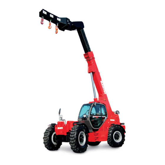
Manitou F-E3 Series Operator's Manual

Manitou F-E3 Series Operator's Manual

Lift truck
Table of Contents

Advertisement

MANITOU BF
BP 10249
44158 ANCENIS CEDEX - FRANCE
TEL: + 33 (0)2 40 09 10 11
YOUR DEALER
647082 EN (19/05/2011)
MLT 634 Turbo LSU Série F-E3
MLT 634 -120 LSU Série F-E3
MLT 634 -120 LSU POWERSHIFT Série F-E3
MLT 731 Turbo Série F-E3
MLT 735 Turbo LSU Série 6-E3
MLT 735 -120 LSU Série 6-E3
MLT 735 -120 LSU POWERSHIFT Série 6-E3
MLT 741 Turbo LSU Série 6-E3
MLT 741 -120 LSU Série 6-E3
MLT 741 -120 LSU POWERSHIFT Série 6-E3
MLT 1035 L Turbo LSU Série 6-E3
OPERATOR'S MANUAL
THIS OPERATOR'S MANUAL MUST BE KEPT IN THE LIFT TRUCK AND MUST BE READ AND UNDERSTOOD BY OPERATORS.

Advertisement

Table of Contents
loading

Summary of Contents for Manitou F-E3 Series

  • Page 1 MANITOU BF BP 10249 44158 ANCENIS CEDEX - FRANCE TEL: + 33 (0)2 40 09 10 11 YOUR DEALER 647082 EN (19/05/2011) MLT 634 Turbo LSU Série F-E3 MLT 634 -120 LSU Série F-E3 MLT 634 -120 LSU POWERSHIFT Série F-E3 MLT 731 Turbo Série F-E3...
  • Page 3 1 - OPERATING AND SAFETY INSTRUCTIONS 2 - DESCRIPTION 3 - MAINTENANCE 4 - ADAPTABLE ATTACHMENTS IN OPTION ON THE RANGE 5 - SPECIFIC AUSTRALIA See also the operator’s manual supplement: 647065 AU 27/08/2010 1ST DATE OF ISSUE 18/10/2010 UP DATING (2-54, 2-55, 3-17) 19/05/2011 UP DATING 2-3 –...
  • Page 5 1 - OPERATING AND SAFETY INSTRUCTIONS...
  • Page 7: Table Of Contents

    TABLE OF CONTENTS INSTRUCTIONS TO THE COMPANY MANAGER 1 - 4 THE SITE 1 - 4 THE OPERATOR 1 - 4 THE LIFT TRUCK 1 - 4 A - THE LIFT TRUCK’S SUITABILITY FOR THE JOB 1 - 4 B - ADAPTATION OF THE LIFT TRUCK TO STANDARD ENVIRONMENTAL CONDITIONS 1 - 4 C - MODIFICATION OF THE LIFT TRUCK 1 - 5...
  • Page 8: Instructions To The Company Manager

    A - THE TRUCK’S SUITABILITY FOR THE JOB - MANITOU has ensured that this lift truck is suitable for use under the standard operating conditions defined in this operator’s manual, with a STATIC test coefficient OF 1.33 and a DYNAMIC test coefficient OF 1, as specified in harmonized norm EN 1459 for variable range trucks.
  • Page 9: C - Modification Of The Lift Truck

    C - MODIFICATION OF THE LIFT TRUCK - For your safety and that of others, you must not change the structure and settings of the various components used in your lift truck (hydraulic pressure, calibrating limiters, I.C. engine speed, addition of extra equipment, addition of counterweight, unapproved attachments, alarm systems, etc.) yourself.
  • Page 10: Instructions For The Operator

    INSTRUCTIONS FOR THE OPERATOR PREAMBLE WHENEVER YOU SEE THIS SYMBOL IT MEANS: WARNING ! BE CAREFUL ! YOUR SAFETY OR THE SAFETY OF THE LIFT TRUCK IS AT RISK. The risk of accident while using, servicing or repairing your lift truck can be restricted if you follow the safety instructions and safety measures detailed in these instruction.
  • Page 11: E - Lifting People

    • Right-hand column - With a PLATFORM-fitted lift truck, people can only be lifted using platforms designed by MANITOU for the purpose. - MANITOU sells equipment specifically designed for lifting people (OPTION PLATFORM lift truck, contact your dealer).
  • Page 12: Operating Instructions Unladen And Laden

    OPERATING INSTRUCTIONS UNLADEN AND LADEN A - BEFORE STARTING THE LIFT TRUCK - Carry out daily maintenance (see: 3 - MAINTENANCE: A - DAILY OR EVERY 10 HOURS SERVICE). - Make sure the lights, indicators and windscreen wipers are working properly. - Make sure the rear view mirrors are in good condition, clean and properly adjusted.
  • Page 13: C - Environment

    C - ENVIRONMENT - Comply with site safety regulations. - If you have to use the lift truck in a dark area or at night, make sure it is equipped with working lights. - During handling operations, make sure that no one is in the way of the lift truck and its load. - Do not allow anybody to come near the working area of the lift truck or pass beneath an elevated load.
  • Page 14: E - Starting The Lift Truck

    E - STARTING THE LIFT TRUCK SAFETY INSTRUCTIONS The lift truck must only be started up or maneuvered when the operator is sitting in the driver’s cab, with his seat belt adjusted and fastened. - Never try to start the lift truck by pushing or towing it. Such operation may cause severe damage to the transmission. If necessary, to tow the lift truck in an emergency, the transmission must be placed in the neutral position (see: 3 - MAINTENANCE: G - OCCASIONAL MAINTENANCE).
  • Page 15: G - Stopping The Lift Truck

    - Use the rear-view mirrors frequently. - Drive round obstacles. - Never drive on the edge of a ditch or steep slope. - It is dangerous to use two lift trucks simultaneously to handle heavy or voluminous loads, since this operation requires particular precautions to be taken.
  • Page 16: H - Driving The Lift Truck On The Public Highway (Or See Current Legislation In Other Countries)

    H - DRIVING THE LIFT TRUCK ON THE PUBLIC HIGHWAY (or see current legislation in other countries) SAFETY INSTRUCTIONS - Operators driving on the public highway must comply with current highway code legislation. - The lift truck must comply with current road legislation. If necessary, there are optional solutions. Contact your dealer. INSTRUCTIONS - Make sure the revolving light is in place, switch it on and verify its operation.
  • Page 17 DRIVING THE LIFT TRUCK WITH A FRONT-MOUNTED ATTACHMENT - You must comply with current regulations in your country, covering the possibility of driving on the public highway with a front- mounted attachment on your lift truck. - If road legislation in your country authorizes circulation with a front-mounted attachment, you must at least: •...
  • Page 18: Instructions For Handling A Load

    A - CHOICE OF ATTACHMENTS - Only attachments approved by MANITOU can be used on its lift trucks. - Make sure the attachment is appropriate for the work to be done (see: 4 - ADAPTABLE ATTACHMENTS IN OPTION ON THE RANGE).
  • Page 19: D - Transverse Attitude Of The Lift Truck

    D - TRANSVERSE ATTITUDE OF THE LIFT TRUCK Depending on the model of lift truck The transverse attitude is the transverse slope of the chassis with respect to the horizontal. Raising the jib reduces the lift truck’s lateral stability. The transverse attitude must be set with the jib in down position as follows: 1 - LIFT TRUCK WITHOUT SLOPE CORRECTOR USED ON TYRES - Position the lift truck so that the bubble in the level is between the two lines (see: 2 -...
  • Page 20: F - Taking Up And Laying A High Load On Tyres

    F - TAKING UP AND LAYING A HIGH LOAD ON TYRES You must not raise the jib if you have not checked the transverse attitude of the lift truck (see: INSTRUCTIONS FOR HANDLING A LOAD: D - TRANSVERSE ATTITUDE OF THE LIFT TRUCK). REMINDER: Make sure that the following operations can be performed with good visibility (see: OPERATIONS INSTRUCTIONS UNLADEN AND LADEN: D - VISIBILITY).
  • Page 21 LAYING A HIGH LOAD ON TYRES - Approach the load in the transport position in front of the pile (fig. F6). - Put the handbrake on and set the forward/reverse selector to neutral. - Lift and extend the jib (1) (2) until the load is above the pile, while keeping an eye on the longitudinal stability limiter and warning device (see: INSTRUCTIONS FOR HANDLING A LOAD: C - LONGITUDINAL STABILITY LIMITER AND WARNING DEVICE).
  • Page 22: G - Taking Up And Laying A High Load On Stabilizers

    G - TAKING UP AND LAYING A HIGH LOAD ON STABILIZERS Depending on the model of lift truck You must not raise the jib if you have not checked the transverse attitude of the lift truck (see: INSTRUCTIONS FOR HANDLING A LOAD: D - TRANSVERSE ATTITUDE OF THE LIFT TRUCK).
  • Page 23 TAKING UP A HIGH LOAD ON STABILIZERS - Make sure the forks will fit easily under the load. - Check the position of the lift truck with respect to the load and make a test run, if necessary, without taking the load. - Raise and extend the jib (1) (2) until the forks are at the level of the load (fig.
  • Page 24: H - Taking Up And Laying Down A Suspended Load

    H - TAKING UP AND LAYING DOWN A SUSPENDED LOAD WARNING: Failure to follow the above instructions may lead the lift truck to loose stability and overturn. MUST be used with a lift truck equipped with an operational hydraulic movement cut-out device. CONDITIONS OF USE - The length of the sling or the chain shall be as short as possible to limit swinging of the load.
  • Page 25: Platform Operating Instructions

    B - SUITABILITY OF THE TRUCK FOR USE - MANITOU has ensured that this lift truck is suitable for use under the standard operating conditions defined in this operator’s manual, with a STATIC test coefficient of 1.25 and a DYNAMIC test coefficient of 1.1, as specified in harmonised standard EN 280 for “mobile elevating work platforms”.
  • Page 26: F - Maintenance

    Operation of the platform is strictly forbidden in the event of wind speeds of over 45 km/h. - The following scale is given for an empiric evaluation of the wind speed: BEAUFORT scale (wind speed at a height of 10 m from flat ground) Speed Speed Speed...
  • Page 27: Instructions For Using The Radio-Control

    INSTRUCTIONS FOR USING THE RADIO-CONTROL For lift trucks with RC radio control HOW TO USE THE RADIO-CONTROL SAFETY INSTRUCTIONS - This radio-control consists of electronic and mechanical safety elements. It cannot receive commands from another transmitter because the internal encoding is unique to each radio-control. If it is used improperly or incorrectly, there is a risk of danger to: - The physical and mental health of the user or others.
  • Page 28: Maintenance Instructions Of The Lift Truck

    MAINTENANCE INSTRUCTIONS OF THE LIFT TRUCK GENERAL INSTRUCTIONS - Ensure the area is sufficiently ventilated before starting the lift truck. - Wear clothes suitable for the maintenance of the lift truck, avoid wearing jewellery and loose clothes. Tie and protect your hair, if necessary.
  • Page 29: Welding

    WELDING - Disconnect the battery before any welding operations on the lift truck. - When carrying out electric welding work on the lift truck, connect the negative cable from the equipment directly to the part being welded, so as to avoid high tension current passing through the alternator. - Never carry out welding or work which gives off heat on an assembled tyre.
  • Page 30: If The Lift Truck Is Not To Be Used For A Long Time

    The following recommendations are intended to prevent the lift truck from being damaged when it is withdrawn from service for an extended period. For these operations, we recommend the use of a MANITOU protective product, reference 603726. Instructions for using the product are given on the packaging.
  • Page 31: Bringing The Lift Truck Back Into Service

    BRINGING THE LIFT TRUCK BACK INTO SERVICE - Remove the waterproof adhesive tape from all the holes. - Refit the intake hose. - Refit and reconnect the battery. - Remove the protection from the cylinder rods. - Perform the daily service (see: 3 - MAINTENANCE: A - DAILY OR EVERY 10 HOURS SERVICE). - Put the handbrake on and remove the axle stands.
  • Page 32 1-28...
  • Page 33 2 - DESCRIPTION...
  • Page 35 TABLE OF CONTENTS « EC» DECLARATION OF CONFORMITY SAFETY PLATES AND STICKERS IDENTIFICATION OF THE LIFT TRUCK 2-10 CHARACTERISTICS MLT 634 Turbo LSU Série F-E3 2-12 CHARACTERISTICS MLT 634 -120 LSU Série F-E3 2-14 CHARACTERISTICS MLT 634 -120 LSU POWERSHIFT Série F-E3 2-16 CHARACTERISTICS MLT 731 Turbo Série F-E3...
  • Page 36 430, rue de l’Aubinière - B.P. 10249 - 44158 - ANCENIS CEDEX - FRANCE Dossier technique, Technical file MANITOU B.F. - 430, rue de l’Aubinière - B.P. 10249 - 44158 - ANCENIS CEDEX - FRANCE Constructeur de la machine décrite ci-après, Manufacturer of the machine described below MLT 634 Turbo LSU Série F-E3 / MLT 634 -120 LSU Série F-E3 / MLT 634 -120 LSU POWERSHIFT Série F-E3...
  • Page 37 bg : 1) cs : 1) da : 1) de : 1) el : 1) es : 1)Declaración DE de conformidad (original), 2) La sociedad, 3) Dirección, 4) expediente técnico, 5) Constructor de la máquina descrita a continuación, 6) Declara que esta máquina, 7) Está...
  • Page 38 SAFETY PLATES AND STICKERS You must replace illegible or damaged plates. Contact your dealer. 1 - EXTERNAL PLATES AND STICKERS MAXI 4A N°256513 GAZ R134A N 234797 N°296998 STOP N 234805 N 234798 CAPACITE DE LEVAGE MAXI : 1500 daN MAXIMUM LOAD LIFT : 1500 daN N°207525...
  • Page 39 2 - STICKERS AND PLATES UNDER THE ENGINE HOOD N 293887 – 35°C 220-240V ; 4.5 A ; 50-60Hz – 31°F N 233088 FUEL / WATER SEPARATOR FUEL 259398 PART NUMBER DESCRIPTION Consult your dealer Engine safety instruction (according to model) 293887 Anti-freeze Consult your dealer...
  • Page 40 Masa en vacio Puissance ISO/TR14396 Power ISO/TR14396 Potenza ISO/TR14396 Potencia ISO/TR14396 Numéro d'homologation MANITOU BF - 44158 ANCENIS CEDEX FRANCE Homologation number Numero d'omologazione Contraseña homologacion Type / Type / Tipo / Tipo / Typ Effort vertical max. (sur accrochage remorque) Vertical max.
  • Page 41 184276 STANDARD MODE HUILE MINERALE Uniquement MINERAL OIL ONLY MINERALÖL Nur ACEITE MINERAL Solamente N°297733 OLIO MINERALE Soltanto LHMS N°268491 DIAG OPT. OPT. OPT. OPT. OPT. OPT. OPT. OPT. STOP HYD. 10A max 15A max 7.5A 7.5A max 15A max 15A max 25A max DIAG...
  • Page 42 NOTE: For the owner’s convenience, it is recommended that a note of these numbers is made in the spaces provided, at the time of the delivery of the lift truck. LIFT TRUCK MANUFACTURER’S PLATE (FIG. A) MANITOU BF - 44158 ANCENIS CEDEX FRANCE - Model Type / Type / Tipo / Tipo / Typ N°...
  • Page 43 FRONT AXLE (FIG. E) FRONT AXLE (FIG. E) - Type - Type - Serial Nr - Serial Nr - MANITOU reference - MANITOU reference REAR AXLE (FIG. F) REAR AXLE (FIG. F) - Type - Type - Serial Nr - Serial Nr...
  • Page 44 CHARACTERISTICS MLT 634 Turbo LSU Série F-E3 I.C. ENGINE Type PERKINS 1104D-44TA NM38858 Fuel Diesel Number of cylinders 4 in line Suction Supercharged Injection system Direct Ignition sequence 1,3,4,2 Capacity 4400 Bore and stroke 105 x 127 Compression ratio 18,2:1 Nominal rating loaded 2200 Rating slow unladen...
  • Page 45 HYDRAULIC CIRCUIT Hydraulic pump Type Variable volume pistons 1st casing Capacity Max. rating capacity unladen l/mn Flow rate at 1600 rpm l/mn Filtration Return μm Suction μm Maximum service pressure Telescoping circuit 200 / 270 Lifting circuit 270 / 270 Tilt circuit 190 / 270 Attachment circuit...
  • Page 46 CHARACTERISTICS MLT 634 -120 LSU Série F-E3 I.C. ENGINE Type PERKINS 1104D-E44TA NJ38698 Fuel Diesel Number of cylinders 4 in line Suction Supercharged Injection system Direct Ignition sequence 1,3,4,2 Capacity 4400 Bore and stroke 105 x 127 Compression ratio 16,2:1 Nominal rating loaded 2200 Rating slow unladen...
  • Page 47 HYDRAULIC CIRCUIT Hydraulic pump Type Variable volume pistons 1st casing Capacity Max. rating capacity unladen l/mn Flow rate at 1600 rpm l/mn Filtration Return μm Suction μm Maximum service pressure Telescoping circuit 200 / 270 Lifting circuit 270 / 270 Tilt circuit 190 / 270 Attachment circuit...
  • Page 48: Mlt 634 -120 Lsu Powershift Série F-E3

    CHARACTERISTICS MLT 634 -120 LSU POWERSHIFT Série F-E3 I.C. ENGINE Type PERKINS 1104D-E44TA NJ38698 Fuel Diesel Number of cylinders 4 in line Suction Supercharged Injection system Direct Ignition sequence 1,3,4,2 Capacity 4400 Bore and stroke 105 x 127 Compression ratio 16,2:1 Nominal rating loaded 2200...
  • Page 49 HYDRAULIC CIRCUIT Hydraulic pump Type Variable volume pistons 1st casing Capacity Max. rating capacity unladen l/mn Flow rate at 1600 rpm l/mn Filtration Return μm Suction μm Maximum service pressure Telescoping circuit 200 / 270 Lifting circuit 270 / 270 Tilt circuit 190 / 270 Attachment circuit...
  • Page 50: Mlt 731 Turbo Série F-E3

    CHARACTERISTICS MLT 731 Turbo Série F-E3 I.C. ENGINE Type PERKINS 1104D-44TA NM38858 Fuel Diesel Number of cylinders 4 in line Suction Supercharged Injection system Direct Ignition sequence 1,3,4,2 Capacity 4400 Bore and stroke 105 x 127 Compression ratio 18,2:1 Nominal rating loaded 2200 Rating slow unladen Max.
  • Page 51 HYDRAULIC CIRCUIT Hydraulic pump Type Gear pump with flow divider 1st casing 2nd casing Capacity Max. rating capacity unladen l/mn Flow rate at 1600 rpm l/mn Filtration Return μm Suction μm Maximum service pressure Telescoping circuit 190 / 260 Lifting circuit 260 / 260 Tilt circuit 190 / 260...
  • Page 52: Mlt 735 Turbo Lsu Série 6-E3

    CHARACTERISTICS MLT 735 Turbo LSU Série 6-E3 I.C. ENGINE Type PERKINS 1104D-44TA NM38858 Fuel Diesel Number of cylinders 4 in line Suction Supercharged Injection system Direct Ignition sequence 1,3,4,2 Capacity 4400 Bore and stroke 105 x 127 Compression ratio 18,2:1 Nominal rating loaded 2200 Rating slow unladen...
  • Page 53 HYDRAULIC CIRCUIT Hydraulic pump Type Variable volume pistons 1st casing Capacity Max. rating capacity unladen l/mn Flow rate at 1600 rpm l/mn Filtration Return μm Suction μm Maximum service pressure Telescoping circuit 200 / 270 Lifting circuit 270 / 270 Tilt circuit 190 / 270 Attachment circuit...
  • Page 54: Mlt 735 -120 Lsu Série 6-E3

    CHARACTERISTICS MLT 735 -120 LSU Série 6-E3 I.C. ENGINE Type PERKINS 1104D-E44TA NJ38698 Fuel Diesel Number of cylinders 4 in line Suction Supercharged Injection system Direct Ignition sequence 1,3,4,2 Capacity 4400 Bore and stroke 105 x 127 Compression ratio 16,2:1 Nominal rating loaded 2200 Rating slow unladen...
  • Page 55 HYDRAULIC CIRCUIT Hydraulic pump Type Variable volume pistons 1st casing Capacity Max. rating capacity unladen l/mn Flow rate at 1600 rpm l/mn Filtration Return μm Suction μm Maximum service pressure Telescoping circuit 200 / 270 Lifting circuit 270 / 270 Tilt circuit 190 / 270 Attachment circuit...
  • Page 56: Mlt 735 -120 Lsu Powershift Série 6-E3

    CHARACTERISTICS MLT 735 -120 LSU POWERSHIFT Série 6-E3 I.C. ENGINE Type PERKINS 1104D-E44TA NJ38698 Fuel Diesel Number of cylinders 4 in line Suction Supercharged Injection system Direct Ignition sequence 1,3,4,2 Capacity 4400 Bore and stroke 105 x 127 Compression ratio 16,2:1 Nominal rating loaded 2200...
  • Page 57 HYDRAULIC CIRCUIT Hydraulic pump Type Variable volume pistons 1st casing Capacity Max. rating capacity unladen l/mn Flow rate at 1600 rpm l/mn Filtration Return μm Suction μm Maximum service pressure Telescoping circuit 200 / 270 Lifting circuit 270 / 270 Tilt circuit 190 / 270 Attachment circuit...
  • Page 58: Mlt 741 Turbo Lsu Série 6-E3

    CHARACTERISTICS MLT 741 Turbo LSU Série 6-E3 I.C. ENGINE Type PERKINS 1104D-44TA NM38858 Fuel Diesel Number of cylinders 4 in line Suction Supercharged Injection system Direct Ignition sequence 1,3,4,2 Capacity 4400 Bore and stroke 105 x 127 Compression ratio 18,2:1 Nominal rating loaded 2200 Rating slow unladen...
  • Page 59 HYDRAULIC CIRCUIT Hydraulic pump Type Variable volume pistons 1st casing Capacity Max. rating capacity unladen l/mn Flow rate at 1600 rpm l/mn Filtration Return μm Suction μm Maximum service pressure Telescoping circuit 200 / 270 Lifting circuit 270 / 270 Tilt circuit 190 / 270 Attachment circuit...
  • Page 60: Mlt 741 -120 Lsu Série 6-E3

    CHARACTERISTICS MLT 741 -120 LSU Série 6-E3 I.C. ENGINE Type PERKINS 1104D-E44TA NJ38698 Fuel Diesel Number of cylinders 4 in line Suction Supercharged Injection system Direct Ignition sequence 1,3,4,2 Capacity 4400 Bore and stroke 105 x 127 Compression ratio 16,2:1 Nominal rating loaded 2200 Rating slow unladen...
  • Page 61 HYDRAULIC CIRCUIT Hydraulic pump Type Variable volume pistons 1st casing Capacity Max. rating capacity unladen l/mn Flow rate at 1600 rpm l/mn Filtration Return μm Suction μm Maximum service pressure Telescoping circuit 200 / 270 Lifting circuit 270 / 270 Tilt circuit 190 / 270 Attachment circuit...
  • Page 62: Mlt 741 -120 Lsu Powershift Série 6-E3

    CHARACTERISTICS MLT 741 -120 LSU POWERSHIFT Série 6-E3 I.C. ENGINE Type PERKINS 1104D-E44TA NJ38698 Fuel Diesel Number of cylinders 4 in line Suction Supercharged Injection system Direct Ignition sequence 1,3,4,2 Capacity 4400 Bore and stroke 105 x 127 Compression ratio 16,2:1 Nominal rating loaded 2200...
  • Page 63 HYDRAULIC CIRCUIT Hydraulic pump Type Variable volume pistons 1st casing Capacity Max. rating capacity unladen l/mn Flow rate at 1600 rpm l/mn Filtration Return μm Suction μm Maximum service pressure Telescoping circuit 200 / 270 Lifting circuit 270 / 270 Tilt circuit 190 / 270 Attachment circuit...
  • Page 64: Mlt 1035 L Turbo Lsu Série 6-E3

    CHARACTERISTICS MLT 1035 L Turbo LSU Série 6-E3 I.C. ENGINE Type PERKINS 1104D-44TA NM38858 Fuel Diesel Number of cylinders 4 in line Suction Supercharged Injection system Direct Ignition sequence 1,3,4,2 Capacity 4400 Bore and stroke 105 x 127 Compression ratio 18,2:1 Nominal rating loaded 2200...
  • Page 65 HYDRAULIC CIRCUIT Hydraulic pump Type Variable volume pistons 1st casing Capacity Max. rating capacity unladen l/mn Flow rate at 1600 rpm l/mn Filtration Return μm Suction μm Maximum service pressure Telescoping circuit 200 / 270 Lifting circuit 270 / 270 Tilt circuit 190 / 270 Tilting corrector circuit...
  • Page 66 FRONT AND REAR TIRES PRESSURE (bar) TYRE LOAD (kg) PRESSURE Front unladen 1550 1550 1600 1750 1700 1750 1750 1700 1750 1750 1800 460/70R24 XMCL 159A8 Front laden 4450 4450 4550 4600 4650 4700 4750 5100 5150 5150 4900 TUBELESS Rear unladen 2050 2050 2100 1950 1900 1850 1900 2100 2050 2100 2400 Rear laden...
  • Page 67 PRESSURE (bar) TYRE LOAD (kg) PRESSURE Front unladen 1550 1550 1600 1750 1700 1750 1750 1700 1750 1750 1800 15,5/80-24 SGI 12PR Front laden 4450 4450 4550 4600 4650 4700 4750 5100 5150 5150 4900 TUBELESS Rear unladen 2050 2050 2100 1950 1900 1850 1900 2100 2050 2100 2400 Rear laden 750 1100 PRESSURE...
  • Page 68 PRESSURE ON THE CONTACT SURFACE AREA OF THE CONTACT SURFACE PRESSURE LOAD (kg/cm2) (cm2) (bar) (kg) HARD SOIL LOOSE SOIL HARD SOIL LOOSE SOIL 7,50 2,07 7,27 1,99 7,05 1,91 6,82 1,83 7,08 1,85 1100 7,25 1,92 1550 7,56 2,04 1600 7,62 2,08...
  • Page 69 PRESSURE ON THE CONTACT SURFACE AREA OF THE CONTACT SURFACE PRESSURE LOAD (kg/cm2) (cm2) (bar) (kg) HARD SOIL LOOSE SOIL HARD SOIL LOOSE SOIL 5,61 1,79 6,20 2,00 1550 7,21 2,35 1600 7,27 2,32 1750 7,44 2,39 3,25 1950 7,65 2,45 2050 7,74...
  • Page 70 PRESSURE ON THE CONTACT SURFACE AREA OF THE CONTACT SURFACE PRESSURE LOAD (kg/cm2) (cm2) (bar) (kg) HARD SOIL LOOSE SOIL HARD SOIL LOOSE SOIL 1800 4900 2400 1100 1,43 0,43 1494 1,46 0,45 1512 1,48 0,48 1531 1,51 0,50 1550 1,56 0,54 1587...
  • Page 71 PRESSURE ON THE CONTACT SURFACE AREA OF THE CONTACT SURFACE PRESSURE LOAD (kg/cm2) (cm2) (bar) (kg) HARD SOIL LOOSE SOIL HARD SOIL LOOSE SOIL 1100 1700 1750 1800 400/80-24 1850 162A8 IND POWER CL 1900 2050 TUBELESS 2100 2400 4650 4700 4750 4900...
  • Page 72 DIMENSIONS AND LOAD CHART MLT 634 Turbo LSU Série F-E3 MLT 634 -120 LSU Série F-E3 MLT 634 -120 LSU POWERSHIFT Série F-E3 1200 (mm) 2560 (mm) 1142 (mm) 1245 (mm) 4579 (mm) 4682 (mm) 4003 (mm) 5779 (mm) 1935 (mm) 1935 (mm)
  • Page 73 MLT634 50° 60° 63.5° 6,05 40° 30° 20° 10° 0° -3.5° 0.5m 3,25 2,55 1,80 1,19 2,05 1,45 SUIVANT NORME EN 1459 annexe B. 2-41...
  • Page 74 DIMENSIONS AND LOAD CHART MLT 731 Turbo Série F-E3 1200 (mm) 2560 (mm) 1142 (mm) 1537 (mm) 4879 (mm) 4974 (mm) 4003 (mm) 6079 (mm) 1935 (mm) 1935 (mm) (mm) (mm) (mm) (mm) (mm) 1260 (mm) (mm) 1715 (mm) (mm) 47,5 (°) (°)
  • Page 75 MLT731 50° 60° 62.5° 40° 6,90 30° 20° 10° 0° -4° 0.5m 4,16 3,10 2,05 1,40 2,50 1,60 SUIVANT NORME EN 1459 annexe B. NOTE: For Australia (see: 5 - SPECIFIC AUSTRALIA) 2-43...
  • Page 76 DIMENSIONS AND LOAD CHART MLT 735 Turbo LSU Série 6-E3 MLT 735 -120 LSU Série 6-E3 MLT 735 -120 LSU POWERSHIFT Série 6-E3 1200 (mm) 2810 (mm) 1192 (mm) 1287 (mm) 4791 (mm) 4886 (mm) 4165 (mm) 5991 (mm) 1935 (mm) 1935 (mm)
  • Page 77 MLT735 50° 60° 61,5° 40° 6,86 30° 20° 10° 0° 0.5m -4° 3.90 2.55 1.70 1.23 3.55 2.05 1.45 SUIVANT NORME EN 1459 annexe B. NOTE: For Australia (see: 5 - SPECIFIC AUSTRALIA) 2-45...
  • Page 78 DIMENSIONS AND LOAD CHART MLT 741 Turbo LSU Série 6-E3 MLT 741 -120 LSU Série 6-E3 MLT 741 -120 LSU POWERSHIFT Série 6-E3 1200 (mm) 2810 (mm) 1232 (mm) 1288 (mm) 4919 (mm) 4975 (mm) 4253 (mm) 6119 (mm) 1935 (mm) 1935 (mm)
  • Page 79 MLT 741 50° 60° 62° 40° 6,84 30° 20° 10° 0° 0,5m -5° 3,93 2,78 1,86 1,25 3,49 2,22 1,40 SUIVANT NORME EN 1459 annexe B. NOTE: For Australia (see: 5 - SPECIFIC AUSTRALIA) Only for MLT 741 -120 LSU POWERSHIFT Série 4-E3 2-47...
  • Page 80 DIMENSIONS AND LOAD CHART MLT 1035 L Turbo LSU Série 6-E3 1200 (mm) 2810 (mm) 1393 (mm) 1325 (mm) 5093 (mm) 5025 (mm) 4267 (mm) 6293 (mm) 1935 (mm) 1935 (mm) (mm) MADE IN FRANCE (mm) (mm) (°) (°) (mm) (mm) 1260 (mm)
  • Page 81 MLT1035LT 50° 60° 60.5° 40° 9,60 30° 20° 10° 0° -5.5° 7,06 5,60 4,80 3,30 6,80 2,75 1,43 SUIVANT NORME EN 1459 annexe B. NOTE: For Australia (see: 5 - SPECIFIC AUSTRALIA) 2-49...
  • Page 82 INSTRUMENTS AND CONTROLS MLT ... LSU ... MLT ... LSU ... POWERSHIFT MLT ... 120 ... MLT 1035 L Turbo LSU Série 6-E3 2-50...
  • Page 83 DESCRIPTION 1 - DRIVER’S SEAT 2 - SAFETY BELT 3 - CONTROL AND SIGNAL LIGHTS PANEL 4 - LONGITUDINAL STABILITY LIMITER AND WARNING DEVICE 5 - EMERGENCY STOP BUTTON 6 - EMERGENCY EXIT 7 - SWITCHES 8 - LIGHT SWITCH, HORN AND INDICATOR SWITCH 9 - FRONT AND REAR WINDSCREEN WIPER SWITCH 10 - IGNITION SWITCH 11 - FUSES AND RELAYS IN THE CAB...
  • Page 84 1 - DRIVER’S SEAT DESIGNED FOR MAXIMUM COMFORT, THIS SEAT CAN BE ADJUSTED AS FOLLOWS. WEIGHT ADJUSTMENT (FIG. A) It is advised that the weight be adjusted when the driver is not sitting in the cab. - Refer to graduation 1 of the seat. - Turn handle 2 depending on the driver’s weight.
  • Page 85 LUMBAR ADJUSTMENT (FIG. F) This increases the comfort of the seat and the driver’s freedom of movement. - Turn the handle either left or right to adjust the height or depth of the lumbar support. ADJUSTMENT OF THE ANGLE OF THE BACK-REST (FIG. G) - Support the back-rest, pull the lever and position the back-rest to find the desired position.
  • Page 86 1 - BASIC PNEUMATIC DRIVER’S SEAT (OPTION) DESIGNED FOR MAXIMUM COMFORT, THIS SEAT CAN BE ADJUSTED AS FOLLOWS. WEIGHT ADJUSTMENT (FIG. A) It is advised that you adjust the seat according to your weight when sitting. - Switch on lift truck ignition. - Push or pull lever 1 until green appears in display 2 indicating correct adjustment according to your weight.
  • Page 87 LUMBAR ADJUSTMENT (FIG. F) This increases the comfort of the seat and the driver’s freedom of movement. - Turn the handle either left or right to adjust the height or depth of the lumbar support. ADJUSTMENT OF THE ANGLE OF THE BACK-REST (FIG. G) - Support the back-rest, pull the lever and position the back-rest to find the desired position.
  • Page 88 3 - CONTROL AND SIGNAL LIGHTS PANEL A1 A2 A3 A4 RPM x 100 CONTROL INSTRUMENTS A - I.C. ENGINE WATER TEMPERATURE Temperature zone: A1 - Blue zone (0° - 50°) Use the lift truck with moderation, wait for temperature to increase before normal operation. A2 - Green zone (50°...
  • Page 89 RED GEAR BOX OIL PRESSURE WARNING INDICATOR LIGHT MLT 634 Turbo LSU Série F-E3 MLT 634 -120 LSU Série F-E3 MLT 731 Turbo Série F-E3 MLT 735 Turbo LSU Série 6-E3 MLT 735 -120 LSU Série 6-E3 MLT 741 Turbo LSU Série 6-E3 MLT 741 -120 LSU Série 6-E3 MLT 1035 L Turbo LSU Série 6-E3 The lamp and buzzer come on when there is an abnormal drop in gear box pressure, in forward gear.
  • Page 90 4 - LONGITUDINAL STABILITY LIMITER AND WARNING DEVICE This device warns the operator of the lift truck’s longitudinal stability limits. However, lateral stability can reduce the load chart in the upper part, and this reduction is not detected by the device.
  • Page 91 C - “SUSPENDED LOAD” MODE Providing a higher margin of safety, use with short jib STANDARD STANDARD or hoisting eye. MODE MODE - Place the lift truck in the transport position. - Press the button for 2 seconds, “SUSPENDED LOAD” MODE is validated by an audible beep and the lighting of the lamp.
  • Page 92 5 - EMERGENCY STOP BUTTON - In the event of danger, it lets you stop the I.C. Engine and thereby cut out all hydraulic movements. - Pull the button to disable it before restarting the lift truck. Be ready for hydraulic movements suddenly stopping when you press this button. 6 - EMERGENCY EXIT EMERGENCY HAMMER Use the emergency hammer to break one of the windows in the event that it is impossible...
  • Page 93 I - REVOLVING LIGHT J - FRONT AND REAR WORKING LIGHTS K - JIB HEAD LIGHT OPTION L - OPTION M - SIDE WINDSCREEN WIPER + ROOF WINDSCREEN WIPER OPTION N/O - OPTION HYDRAULIC TOWING HOOK WITH SINGLE OR DUAL EFFECT REAR HYDRAULIC PREDISPOSITION See: 2 - DESCRIPTION: DESCRIPTION AND USE OF THE OPTIONS.
  • Page 94 8 - LIGHT SWITCH, HORN AND INDICATOR SWITCH The switch controls the visual and sound alarms. A - All lights are off, the direction indicators do not flash. B - The right hand direction indicators flash. C - The left hand direction indicators flash. D - The sidelights and the rear lights are on.
  • Page 95 11 - FUSES AND RELAYS IN THE CAB - Lift up the fuse and relay access panel 1. NOTE: A sticker on the inside of the access panel gives a clear display of the use of the components described below. Always replace a faulty fuse with another of equivalent rating.
  • Page 96 F31 - Starter (25A). F32 - Diagnostic socket (5A). - Hydraulic movement control unit (5A). K0 - OPTION. K1 - Transmission cut-off relay. K2 - Transmission cut-off relay. except MLT ... POWERSHIFT ... K3 - Reverse gear relay. K4 - Forward gear relay. except MLT ...
  • Page 97 12 - FUSES AND RELAYS UNDER THE ENGINE HOOD Remove casing 1 and cover 2 for access to fuses and relays. Always replace a faulty fuse with another of equivalent rating. Never use a fuse that has been repaired. F40 - Key switch (40A). MLT …...
  • Page 98 14 - ACCELERATOR PEDAL 15 - SERVICE BRAKE PEDAL AND TRANSMISSION CUT-OFF The pedal applies on the front and rear wheels by an hydraulic brake system, and allows the lift truck to be slowed down and stopped. Depending on the position of the transmission cut-off switch, it enables the free travel to cut off transmission (see: 2 - DESCRIPTION: 5 - SWITCHES).
  • Page 99 16 - GEAR SELECTOR MLT 634 -120 LSU POWERSHIFT Série F-E3 MLT 735 -120 LSU POWERSHIFT Série 6-E3 MLT 741 -120 LSU POWERSHIFT Série 6-E3 The gear is selected by means of buttons 1 and 2. The selected gear is indicated on the dial 3.
  • Page 100 18 - FORWARD/NEUTRAL/REVERSE GEAR SELECTION FORWARD: Push the knob forward (position A). REVERSE: Pull the knob backwards (position B). NEUTRAL: The knob must be in the intermediate position to start the lift truck (position When operating this control, the lift truck should be travelling at slow speed and not accelerating. NOTE: The reverse lights indicate that the lift truck is running in reverse motion.
  • Page 101 20 - HYDRAULIC CONTROLS AND TRANSMISSION CUT-OFF Do not attempt to alter the hydraulic system pressure by interfering with the pressure regulating valve. In the event of suspected malfunction, contact your dealer. ANY ALTERATION MAY RENDER THE WARRANTY NULL AND VOID. Use the hydraulic controls carefully without jerking, to avoid accidents caused byshaking the lift truck.
  • Page 102 21 - FUNCTION FILES These files contain the description of the hydraulic controls and the load charts for the attachments used on the lift truck. 22 - LEVEL INDICATOR Except for MLT 1035 L Turbo LSU Série 6-E3 Enables the operator to check that the lift truck is in the horizontal position. 22 - LEVEL INDICATORS Only for MLT 1035 L Turbo LSU Série 6-E3 A - TILT INDICATOR...
  • Page 103 23 - AIR CONDITIONING CONTROLS (OPTION AIR CONDITIONING) The air conditioning only comes on when the forklift truck has been started up. When using your air conditioning, you must work with the doors and windows closed. In winter: So as to ensure correct operation and complete efficiency of the air conditioning unit, start up the compressor once a week, if only for a short spell, so as to lubricate the internal seals.
  • Page 104 27 - BRAKING OIL AND WINDSCREEN WASHER TANK ACCESS PANEL - Loosen screw 1 and lift up the braking oil and windscreen washer tank access panel (see: 3 - MAINTENANCE: B - EVERY 50 HOURS OF SERVICE). 28 - STEERING WHEEL REGULATING HANDLE This handle enables the angle and height of the steering wheel to be adjusted.
  • Page 105 33 - DOCUMENT HOLDER Ensure that the operator’s manual is in its place in the document holder. 34 - SUN VISOR 35 - OVERHEAD LIGHT 36 - HOOK 37 - CIGAR LIGHTER For 12 V appliance and max. amperage 10A. 2-73...
  • Page 106 38 - ARMREST AND STORAGE - Lift the armrest 1 to access the storage. 39 - CAR RADIO (OPTION) 40 - INSIDE REAR-VIEW MIRROR (OPTION) 41 - TOOL BOX Except for MLT 1035 L Turbo LSU Série 6-E3 42 - NUMBER PLATE 43 - NUMBER PLATE LIGHTING 44 - REAR REFLECTORS 2-74...
  • Page 107 45 - FRONT HEADLIGHTS A - Left front indicator. B - Left front dipped headlight. C - Left front main beam. D - Left front sidelight. E - Right front indicator. F - Right front dipped headlight. G - Right front main beam. H - Right front sidelight.
  • Page 108 TOWING PIN AND HOOK Located at the rear of the lift truck, this device is used to attach a trailer. Its capacity is limited for each lift truck by the Authorized Gross Vehicle Weight, tractive force and maximum vertical force on the coupling point. - To use a trailer, see current regulations in your country (maximum running speed, braking, maximum weight of trailer, etc.).
  • Page 109 C - TRAILER BRAKE SYSTEM. - Connect the brake hose to the provided brake unit 1 on the lift truck. - Make sure the trailer brakes are working properly and test the effects of braking before taking the trailer onto the public highway. D - CHASSIS-MOUNTED FRONT TOWING HOOK COUPLING AND UNCOUPLING THE TRAILER - To couple the trailer, position the lift truck as close as possible to the trailer ring.
  • Page 110 F - HYDRAULIC TOWING HOOK (OPTION) Never use the tow hook to raise the rear of the lift truck (when changing the rear wheel for example). - Raise the hydraulic tow hook to release the hook lock 1 by pressing the upper part of switch 2.
  • Page 111 2-79...
  • Page 112 DESCRIPTION AND USE OF THE OPTIONS 1 - BATTERY CUT-OFF 2 - REVERSE BUZZER ALARM 3 - PREHEATING ELEMENT 4 - CLEANFIX SELF-CLEANING FAN 5 - MODCOD ANTI-THEFT SYSTEM 6 - FINTRONIC ANTI-START SYSTEM 7 - MODCLÉ ANTI-START SYSTEM 8 - ATTACHMENT HYDRAULIC CONTROL FORCED OPERATION 9 - JIB SUSPENSION 10 - ATTACHMENT EASY HYDRAULIC CONNECTION 11 - PROVISION FOR ELECTRICAL JIB...
  • Page 113 1 - BATTERY CUT-OFF MLT ... -120 ... MLT ... Turbo ... 2 - REVERSE BUZZER ALARM 3 - PREHEATING ELEMENT Enables the engine to be kept warm during prolonged periods of stoppage and thus improves engine starting. SUPPLY CHARACTERISTICS OF PREHEATING SYSTEM: •...
  • Page 114 5 - MODCOD ANTI-THEFT SYSTEM OPERATION - Switch on the lift truck: the red indicator 1 will flash. - Enter your user code followed by “V” to validate: the green indicator 2 will come on. - Start the lift truck within the next 60 seconds; otherwise the anti-theft system will be reactivated and the red indicator 1 will flash.
  • Page 115 8 - ATTACHMENT HYDRAULIC CONTROL FORCED OPERATION This OPTION must only be used with an attachment requiring continuous hydraulic movement of type: brush, supply bucket, mixer, spray… It is strictly forbidden in handling operations and at all other events (winch, crane boom, crane boom with winch, hook, etc.). CONTINUOUS HYDRAULIC MOVEMENT OF THE ATTACHMENT - Make sure the potentiometer C is set to 0%.
  • Page 116 10 - ATTACHMENT EASY HYDRAULIC CONNECTION For easily connecting and disconnecting the attachment. OPERATION - Switch on lift truck ignition. - Press for two seconds on push-button 1 to release the attachment circuit hydraulic pressure. - Connect or disconnect the rapid connectors of the hydraulic attachment (see: 4 - OPTIONAL ATTACHMENTS FOR USE WITH THE RANGE: PICKING UP THE ATTACHMENTS).
  • Page 117 13 - HYDRAULIC ATTACHMENT LOCKING Enables the attachment to be locked onto the carriage and a hydraulic attachment to be used by the same hydraulic circuit. ATTACHMENT LOCKING CONTROL - Set valve 1 to position A and place switch 2 in position B (indicator light on). - Push button 3 forward to lock the attachment and backward to release it.
  • Page 118 15 - MACH2 QUICK-RELEASE COUPLERS ON ACCESSORY CIRCUIT Enables the use of a hydraulic attachment fitted with MACH2 quick-release couplers. CONNECTING A HYDRAULIC ATTACHMENT - Lower lever 1 and valve 2 and connect the MACH2 quick-release couplers on the attachment. - Lift up lever 1 to lock the connection.
  • Page 119 18 - LIFTING RING ON SINGLE CARRIAGE CONDITIONS OF USE Follow the instructions given in the instruction manual (see: 1 - OPERATING AND SAFETY INSTRUCTIONS: INSTRUCTIONS FOR HANDLING LOADS). - The lifting ring must be used WITHOUT FORKS AND ATTACHMENTS, but the angle of inclination of the carriage must be same as when the forks are used in the horizontal position.
  • Page 120 LOAD CHARTS AND FUNCTION SHEETS MLT7.. + TS AS 3T MLT7.. + TS AS 3T MLT 741 ... The load charts are given for use without forks and without attachments. MLT1035 + TS AS 3.5T MLT1035 + TS AS 3.5T LOAD CHARTS AND FUNCTION SHEETS MLT 1035 ...
  • Page 121 19 - ANGULAR SECTOR ON JIB The angular sector displays the jib angle, and thus improves the reading of the load charts. 20 - SINGLE OR DUAL EFFECT REAR HYDRAULIC CONTROL PREDISPOSITION Enables the use of a hydraulic attachment at the rear of the lift truck (e.g. a trailer with hydraulic tipping).
  • Page 122 21 - DUAL EFFECT REAR HYDRAULIC CONTROL PREDISPOSITION + SINGLE OR DUAL EFFECT REAR HYDRAULIC CONTROL PREDISPOSITION Enables the use of a hydraulic attachment at the rear of the lift truck or another hydraulic attachment at the rear of the lift truck. DUAL EFFECT L1 AND SINGLE EFFECT L2 REAR HYDRAULIC CONTROL DUAL EFFECT ATTACHMENT L1 - Set switch 1 to position A (indicator light off).
  • Page 123 22 - HYDRAULIC TOWING HOOK + SINGLE OR DUAL EFFECT REAR HYDRAULIC CONTROL PREDISPOSITION Enables the use of the trailer eye (see: 2 - DESCRIPTION: TRAILER PIN AND HOOK) or a hydraulic attachment at the rear of the lift truck. HYDRAULIC TRAILER HOOK + SINGLE EFFECT REAR HYDRAULIC CONTROL L1 HYDRAULIC TRAILER HOOK - Set switch 1 to position A (indicator light off).
  • Page 124 2-92...
  • Page 125 3 - MAINTENANCE...
  • Page 127 TABLE OF CONTENTS MANITOU ORIGINAL SPARE PARTS AND EQUIPMENT START-UP CHECKLIST FILTERS CARTRIDGES AND BELTS MLT 731 Turbo Série F-E3 FILTERS CARTRIDGES AND BELTS MLT 634 Turbo LSU Série F-E3 MLT 735 Turbo LSU Série 6-E3 MLT 741 Turbo LSU Série 6-E3 MLT 1035 L Turbo LSU Série 6-E3...
  • Page 128 - Improvements due to experience feedback. - Operator training. - Only the MANITOU network has detailed knowledge of the design of the lift truck and therefore the best technical ability to provide maintenance. ORIGINAL REPLACEMENT PARTS ARE DISTRIBUTED EXCLUSIVELY BY MANITOU AND ITS DEALER NETWORK.
  • Page 129 START-UP CHECKLIST 0 = OK 1 = Missing 2 = Incorrect ENGINE ATTACHMENTS 01 Air filter 01 Fitting on machine 02 Fuel tank 02 Hydraulic couplings 03 Fuel lines - Filter CABIN/PROTECTOR/ELECTRIC CIRCUIT 04 Injection or carburetion system 01 Seat 05 Radiator and cooling system 02 Dashboard and radio 06 Belts...
  • Page 130 FILTERS CARTRIDGES AND BELTS MLT 731 Turbo Série F-E3 I.C. ENGINE I.C. ENGINE OIL FILTER ALTERNATOR BELT Part number: 476954 Part number: 702974 Change: 500 H DRY AIR FILTER CARTRIDGE Part number: 563416 FAN BELT Clean: 50 H* Part number: 257524 Change: 500 H* SAFETY DRY AIR FILTER CARTRIDGE COMPRESSOR BELT...
  • Page 131 FILTERS CARTRIDGES AND BELTS MLT 634 Turbo LSU Série F-E3 MLT 735 Turbo LSU Série 6-E3 MLT 741 Turbo LSU Série 6-E3 MLT 1035 L Turbo LSU Série 6-E3 I.C. ENGINE I.C. ENGINE OIL FILTER ALTERNATOR BELT Part number: 476954 Part number: 702974 (MLT 634 T...
  • Page 132 FILTERS CARTRIDGES AND BELTS MLT 634 -120 LSU Série F-E3 MLT 634 -120 LSU POWERSHIFT Série F-E3 MLT 735 -120 LSU Série 6-E3 MLT 735 -120 LSU POWERSHIFT Série 6-E3 MLT 741 -120 LSU Série 6-E3 MLT 741 -120 LSU POWERSHIFT Série 6-E3 I.C.
  • Page 134 USE THE RECOMMENDED LUBRICANTS AND FUEL: - For topping up, oils may not be miscible. - For oil changes, MANITOU oils are perfectly appropriate. DIAGNOSTIC ANALYSIS OF OILS If a service or maintenance contract has been organized with the dealer, a diagnostic analysis of engine, gear box and axle oils may be requested depending on the rate of use.
  • Page 135 HYDRAULIC ORGANS TO BE LUBRICATED CAPACITY RECOMMENDATION PACKAGING PART NUMBER 545500 MANITOU Oil 20 l 582297 HYDRAULIC OIL TANK 135 Litres Hydraulic ISO VG 46 55 l 546108 209 l 546109 BRAKE ORGANS TO BE LUBRICATED RECOMMENDATION PACKAGING PART NUMBER...
  • Page 136 SERVICING SCHEDULE (1): MANDATORY 500 HOUR OR 6 MONTH SERVICE This service must be carried out after approximately the first 500 hours of operation or within the 6 months following the start-up of the machine (whichever occurs first). A = ADJUST, C = CHECK, G = GREASE, N = CLEAN, PAGE P = BLEED, R = REPLACE, V = DRAIN I.C.
  • Page 137 A = ADJUST, C = CHECK, G = GREASE, N = CLEAN, PAGE P = BLEED, R = REPLACE, V = DRAIN BRAKE Brake oil level 3-22 <<< <<< <<< <<< <<< Parking brake 3-28 <<< <<< <<< <<< Parking brake lever mechanism 3-34 <<<...
  • Page 138 A - DAILY OR EVERY 10 HOURS SERVICE A1 - I.C. ENGINE OIL LEVEL CHECK Place the lift truck on level ground with the I.C. engine stopped, and let the oil drain into the sump. - Open the I.C. engine bonnet. - Remove the dipstick 1 (fig.
  • Page 139 A3 - FUEL LEVEL CHECK Keep the fuel tank full, to reduce as much as possible any condensation due to the atmospheric conditions. - Remove cap 1 (fig. A3). - Fill the fuel tank with clean fuel (see: 3 - MAINTENANCE: LUBRICANTS AND FUEL), filtered through a strainer or a clean, lint free cloth, through filler port 2 (fig.
  • Page 140 - Telescope the boom several times in order to spread the coat of grease evenly. - Remove the surplus of grease. If the lift truck is used in an abrasive environment (dust, sand, coal…) Use lubricating varnish (MANITOU reference: 483536). In this respect, consult your dealer.
  • Page 141 A9 - LONGITUDINAL STABILITY LIMITER AND WARNING DEVICE CHECK - These tests are essential for checking the correct operation and adjustment of the different components of the device. - Place the lift truck on flat, level ground with the wheels straight. Use the test button only when requested to do so, performing short presses (less than 1 second) and long presses (5 seconds) as instructed.
  • Page 142 The error codes are indicated by leds A3 to A7 on the warning device and longitudinal stability limiter. ERROR CODES LEDS DESIGNATIONS Regulating fault (fault detected during the test). Lowering regulating valve fault. Safety valve cut-off fault (fault detected during the test). Safety valve fault.
  • Page 143 3-19...
  • Page 144 Never clean the cartridge by tapping it against a hard surface. Your eyes must be protected during this intervention. - Clean the cartridge seal surfaces with a damp, clean lint-free cloth and grease with a silicone lubricant (MANITOU reference: 479292).
  • Page 145 B4 - BOOM GREASE To be carried out weekly, if the lift truck has been operated for less than 50 hours during the week. In the event of prolonged use in an extremely dusty or oxidising atmosphere, reduce this interval to 10 working hours or every day. - Clean and lubricate the following points with grease (see: 3 - MAINTENANCE: LUBRICANTS AND FUEL) and remove the surplus of grease.
  • Page 146 B5 - HYDRAULIC OIL LEVEL B5/1 CHECK Place the lift truck on level ground with the I.C. engine stopped, and the boom retracted and lowered as far as possible. - Refer to gauge 1 (fig. B5/1). - The oil level is correct when it is at the level of the red point. - If necessary, add oil (see: 3 - MAINTENANCE: LUBRICANTS AND FUEL).
  • Page 147 B7 - WINDSCREEN WASHER LIQUID LEVEL B7/1 CHECK - Loosen screw 1 (fig. B7/1) and remove the access panel for braking oil tank and windscreen washer tank 2 (fig. B7/1). - Visually check the level. - If necessary add windscreen washer liquid (see: 3 - MAINTENANCE: LUBRICANTS AND FUEL) by filler port 3 (fig.
  • Page 148 B10 - FRONT AND REAR WHEEL REDUCER PIVOTS GREASE - Clean and lubricate the points 1 (8 lubricators) (fig. B10) with grease (see: 3 - MAINTENANCE: LUBRICANTS AND FUEL) and remove the surplus of grease. B11 - FRONT AXLE OSCILLATION GREASE MLT 1035 L Turbo LSU Série 6-E3 - Clean and lubricate the points 1 (2 lubricators) (fig.
  • Page 149 3-25...
  • Page 150 C - EVERY 250 HOURS SERVICE Carry out the operations described previously as well as the following operations. C1 - FAN BELT TENSION C1/1 CHECK - ADJUST - Open the I.C. engine bonnet. - Check the belt for signs of wear and cracks and change if necessary (see: 3 - MAINTENANCE: FILTERS CARTRIDGES AND BELTS).
  • Page 151 MLT 741 -120 LSU Série 6-E3 MLT 741 -120 LSU POWERSHIFT Série 6-E3 MLT 1035 L Turbo LSU Série 6-E3 For this operation, we advise you to use the MANITOU tension meter (fig. C2/1) reference C2/2 167418. - Open the I.C. engine bonnet.
  • Page 152 C4 - ANGLE GEAR BOX LEVEL CHECK Park the lift truck on level ground with the jib raised and the I.C. engine stopped. - Remove level plug 1 (fig. C4). - Wipe the dipstick and check the correct level between the MIN and MAX marks. - If necessary, add oil (see: 3 - MAINTENANCE: E5 - ANGLE GEAR BOX OIL).
  • Page 153 C8 - FRONT AND REAR DIFFERENTIAL OIL LEVEL CHECK Place the lift truck on level ground with the I.C. engine stopped. - Remove level plug 1 (fig. C8). The oil should be flush with the edge of the hole. - If necessary, add oil (see: 3 - MAINTENANCE: LUBRICANTS AND FUEL) by the filler port 2 (fig.
  • Page 154 D - EVERY 500 HOURS SERVICE Carry out the operations described previously as well as the following operations. D1 - I.C. ENGINE OIL D1/1 DRAIN D2 - I.C. ENGINE OIL FILTER CHANGE Place the lift truck on level ground, let the I.C. engine run at idle for a few minutes, then stop the I.C.
  • Page 155 D3 - DRY AIR FILTER CARTRIDGE CHANGE In case of use in a heavily dust laden atmosphere, there are pre-filtration cartridges, see: 3 - MAINTENANCE: FILTERS CARTRIDGES AND BELTS. Also, the checking and cleaning periodicity of the cartridge must be reduced (up to 250 hours in a heavily laden dust atmosphere and with pre-filtration).
  • Page 156 D5 - FUEL FILTER D5/1 CHANGE MLT 634 Turbo LSU Série F-E3 MLT 731 Turbo Série F-E3 MLT 735 Turbo LSU Série 6-E3 MLT 741 Turbo LSU Série 6-E3 MLT 1035 L Turbo LSU Série 6-E3 Make sure the electrical contact on the lift truck is cut, otherwise fuel will be released if the lift pump is on.
  • Page 157 D6 - CLEANFIX COMPRESSOR FILTER (OPTION) D6/1 CHANGE - Open the I.C. engine bonnet. - Remove compressor securing nut 1 (fig. D6/1). - Remove clip 2 (fig. D6/2). - Replace filter 3 (fig. D6/2) with a new one (see: 3 - MAINTENANCE: FILTERS CARTRIDGES AND BELTS) and correctly refit clip 2 (fig.
  • Page 158 D8 - HYDRAULIC RETURN OIL FILTER CARTRIDGE CHANGE Stop the I.C. engine and remove the pressure from the circuits by acting on the hydraulic controls. Thoroughly clean the outside of the filter and its surroundings before any intervention in order to prevent any risk of polluting the hydraulic circuit.
  • Page 159 D11 - FRONT AND REAR AXLE DIFFERENTIAL OIL DRAIN Place the lift truck on level ground with the I.C. engine stopped and the differential oil still warm. Dispose of the drain oil in an ecological manner. - Place a container under drain plugs 1 (fig. D11) and unscrew the plugs. - Remove level plug 2 (fig.
  • Page 160 E - EVERY 1000 HOURS SERVICE Carry out the operations described previously as well as the following operations. E1 - FUEL TANK E1/1 CLEAN While carrying out these operations, do not smoke or work near a flame. Place the lift truck on level ground with the I.C. engine stopped. - Inspect the parts susceptible to leaks in the fuel circuit and in the tank.
  • Page 161 E3 - GEAR BOX OIL E3/1 DRAIN E4 - GEAR BOX SUMP STRAINER CLEAN MLT 634 Turbo LSU Série F-E3 MLT 634 -120 LSU Série F-E3 MLT 731 Turbo Série F-E3 MLT 735 Turbo LSU Série 6-E3 MLT 735 -120 LSU Série 6-E3 MLT 741 Turbo LSU Série 6-E3 MLT 741 -120 LSU Série 6-E3 MLT 1035 L Turbo LSU Série 6-E3...
  • Page 162 E3 - GEAR BOX OIL E3/1 DRAIN E4 - GEAR BOX SUMP STRAINER CLEAN MLT 634 -120 LSU POWERSHIFT Série F-E3 MLT 735 -120 LSU POWERSHIFT Série 6-E3 MLT 741 -120 LSU POWERSHIFT Série 6-E3 Place the lift truck on level ground with the I.C. engine stopped, the gear box oil still warm.
  • Page 163 E5 - ANGLE GEAR BOX OIL E5/1 DRAIN Place the lift truck on level ground with the I.C. engine stopped, the angle gear box oil still warm. - Place a container under drain plug 1 (fig. E5/1) and unscrew the plug. - Remove dipstick 2 (fig.
  • Page 164 REPLACING THE DISTRIBUTOR CONTROL HEAD FILTER E6/4 MLT 634 Turbo LSU Série F-E3 MLT 634 -120 LSU Série F-E3 MLT 634 -120 LSU POWERSHIFT Série F-E3 MLT 735 Turbo LSU Série 6-E3 MLT 735 -120 LSU Série 6-E3 MLT 735 -120 LSU POWERSHIFT Série 6-E3 MLT 741 Turbo LSU Série 6-E3 MLT 741 -120 LSU Série 6-E3 MLT 741 -120 LSU POWERSHIFT Série 6-E3...
  • Page 165 E10 - SEAT BELT CHECK SEAT BELT WITH TWO ANCHORING POINTS - Check the following points: • Fixing of the anchoring points on the seat. • Cleanness of the strap and the locking mechanism. • Triggering of the locking mechanism. •...
  • Page 166 F - EVERY 2000 HOURS OF SERVICE Carry out the operations described previously as well as the following operations. F1 - COOLING LIQUID F1/1 DRAIN These operations are to be carried out if necessary or every two years at the beginning of winter.
  • Page 167 F2 - AIR CONDITIONING (OPTION) CLEANING - INSPECTION CLEANING CONDENSER AND EVAPORATOR COILS (*) CLEANING CONDENSATE TRAY AND RELIEF VALVE (*) COLLECTING COOLANT TO REPLACE FILTER-DRIER (*) REFILLING WITH COOLANT AND CHECKING THE THERMOSTATIC CONTROL AND PRESSURE SWITCHES (*) NOTE: When opening the evaporator unit, remember to replace the cover seal. (*): (CONSULT YOUR DEALER).
  • Page 168 G - OCCASIONAL MAINTENANCE G1 - FUEL SYSTEM G1/1 BLEED MLT 634 Turbo LSU Série F-E3 MLT 731 Turbo Série F-E3 MLT 735 Turbo LSU Série 6-E3 MLT 741 Turbo LSU Série 6-E3 MLT 1035 L Turbo LSU Série 6-E3 These operations are to be carried out only in the following cases: •...
  • Page 169 CHANGE In the event of a wheel being changed on the public highway, make sure of the following points: For this operation, we advise you to use the hydraulic jack MANITOU reference 505507 and the safety support MANITOU reference 554772.
  • Page 170 G5 - LIFT TRUCK G5/1 SLING - Take into account the position of the lift truck centre of gravity for lifting (fig. G5/1). A = 1450 mm B = 1110 mm MLT 634 . . . A = 1345 mm B = 1215 mm MLT 731 T A = 1485 mm B = 1325 mm MLT 735 T LSU...
  • Page 171 G7 - LONGITUDINAL STABILITY LIMITER AND WARNING DEVICE RESET According to the use of the lift truck, the device may require to be periodically reset. This operation can be easily performed by means of the following procedure. - Provide a fork carrier or a bucket and a load corresponding to at least half the lift truck’s rated capacity. - Preferably perform the reset when the lift truck is still cold (before it is used) or ensure that the temperature of the rear axle is not more than 50°C.
  • Page 172 3-48...
  • Page 173 4 - OPTIONAL ATTACHMENTS FOR USE WITH THE RANGE...
  • Page 175 TABLE OF CONTENTS INTRODUCTION PICKING UP THE ATTACHMENTS TECHNICAL SPECIFICATIONS OF ATTACHMENTS ATTACHMENT SHIELDS 4-18...
  • Page 177 INSTRUCTIONS: H - TAKING-UP AND SETTING-DOWN A SUSPENDED LOAD). Only attachments approved by MANITOU are to be used on our lift trucks (see: 4 - ADAPTABLE ATTACHMENTS IN OPTION ON THE RANGE: TECHNICAL SPECIFICATIONS OF ATTACHMENTS). The manufacturer’s liability will be denied in case of modification or of attachment adaptation carried out without his knowing it.
  • Page 178 PICKING UP THE ATTACHMENTS A - ATTACHMENT WITHOUT HYDRAULICS AND HAND LOCKING DEVICE TAKING UP AN ATTACHMENT - Ensure that the attachment is in a position facilitating the locking to the carriage. If it is not correctly oriented, take the necessary precautions in order to move it safely. - Check that the locking pin and the clip are in position in the bracket (fig.
  • Page 179 B - HYDRAULIC ATTACHMENT AND HAND LOCKING DEVICE TAKING UP AN ATTACHMENT - Ensure that the attachment is in a position facilitating the locking to the carriage. If it is not correctly oriented, take the necessary precautions in order to move it safely. - Check that the locking pin and the clip are in position in the bracket (fig.
  • Page 180 TECHNICAL SPECIFICATIONS OF ATTACHMENTS FLOATING FORK CARRIAGE MLT 634 Turbo LSU Série F-E3 MLT 634 -120 LSU Série F-E3 MLT 634 -120 LSU POWERSHIFT Série F-E3 MLT 731 Turbo Série F-E3 MLT 735 Turbo LSU Série 6-E3 MLT 735 -120 LSU Série 6-E3 MLT 735 -120 LSU POWERSHIFT Série 6-E3 MLT 1035 L Turbo LSU Série 6-E3 TFF 35 MT-1040...
  • Page 181 FLOATING FORK MLT 634 Turbo LSU Série F-E3 MLT 634 -120 LSU Série F-E3 MLT 634 -120 LSU POWERSHIFT Série F-E3 MLT 731 Turbo Série F-E3 MLT 735 Turbo LSU Série 6-E3 MLT 735 -120 LSU Série 6-E3 MLT 735 -120 LSU POWERSHIFT Série 6-E3 MLT 1035 L Turbo LSU Série 6-E3 PART NUMBER 415801...
  • Page 182 STANDARDISED TILTING FORK CARRIAGE MLT 634 Turbo LSU Série F-E3 MLT 634 -120 LSU Série F-E3 MLT 634 -120 LSU POWERSHIFT Série F-E3 MLT 731 Turbo Série F-E3 MLT 735 Turbo LSU Série 6-E3 MLT 735 -120 LSU Série 6-E3 MLT 735 -120 LSU POWERSHIFT Série 6-E3 MLT 1035 L Turbo LSU Série 6-E3 PFB 35 N MT-1260 S2...
  • Page 183 STANDARDISED FORK MLT 634 Turbo LSU Série F-E3 MLT 634 -120 LSU Série F-E3 MLT 634 -120 LSU POWERSHIFT Série F-E3 MLT 731 Turbo Série F-E3 MLT 735 Turbo LSU Série 6-E3 MLT 735 -120 LSU Série 6-E3 MLT 735 -120 LSU POWERSHIFT Série 6-E3 MLT 1035 L Turbo LSU Série 6-E3 PART NUMBER 415618...
  • Page 184 BUILDING BUCKET CBC 700 L1950 S2 CBC 800 L2250 S3 CBC 900 L2450 S3 PART NUMBER 654472 654471 654470 Rated capacity 697 l 814 l 893 l Width 1950 mm 2250 mm 2450 mm Weight 330 kg 385 kg 410 kg LOADING BUCKET CBR 780 L1950 S2 CBR 900 L2250 S2...
  • Page 185 BUCKET 4X1 CB4x1-700 L1950 CB4x1-850 L2300 CB4x1-900 L2450 PART NUMBER 751402 751401 751465 Rated capacity 700 l 850 l 900 l Width 1950 mm 2300 mm 2450 mm Weight 640 kg 735 kg 765 kg MULTIPURPOSE BUCKET (REVERSING AND DISMOUNTABLE CUTTING EDGE) CBM 2450 LDR S5 PART NUMBER 752195...
  • Page 186 GRAB BUCKET CBG 1950 S4 CBG 2300 S4 CBG 2450 S4 PART NUMBER 751407 751414 751418 Rated capacity 1 m3 1,2 m3 1,26 m3 Width 1950 mm 2300 mm 2450 mm Grab Weight 555 kg 615 kg 635 kg GRAB BUCKET (NON-HAZARDOUS INDUSTRIAL WASTE) CBG 1950 DIB S4 CBG 2300 DIB S4 CBG 2450 DIB S4...
  • Page 187 CONCRETE BUCKET (ADAPTABLE ON FORKS) BB 500 S4 BBH 500 S4 PART NUMBER 654409 751462 Rated capacity 500 l/1300 kg 500 l/1300 kg Width 1100 mm 1100 mm Weight 205 kg 220 kg CONCRETE BUCKET WITH SPOUT(ADAPTABLE ON FORKS) BBG 500 S4 BBHG 500 S4 PART NUMBER 654411...
  • Page 188 MANURE FORK WITH GRAB FFGR 30 MT 2100 S5 FFGR 30 MT 2400 S5 FFGR 30 MT 2100 DR PART NUMBER 556843 570594 570728 Rated capacity 1700 Kg 1700 Kg 1700 Kg Width 2100 mm 2400 mm 2100 mm Finger 10 (round finger) Grab Weight...
  • Page 189 CRANE JIB P 600 MT S3 PART NUMBER 653228 Rated capacity 600 kg Weight 170 kg CRANE JIB P 4000 MT S2 PART NUMBER 653226 Rated capacity 4000 kg/1200 kg Weight 210 kg CRANE JIB WITH WINCH PT 600 MT S6 PART NUMBER 708538 Rated capacity...
  • Page 190 ATTACHMENT SHIELDS FORK PROTECTOR PART NUMBER 227801 FORK BLOCK FOR FLOATING FORK CARRIAGE PART NUMBER 261210 BUCKET PROTECTOR NOTE: Always ensure that the width of the protector you choose is less than or equal to the width of the bucket. PART NUMBER 206734 206732...
  • Page 191 5 - SPECIFIC AUSTRALIA See also the operator’s manual supplement: 647065 AU...
  • Page 193 LOAD CHART MLT 731 Turbo Série F-E3 MLT731 50° 60° 62.5° 40° 6.90m 36km/h Maxi (10m/s) Ground conditions: solid surface 30° 20° 12km/h Maxi (3,33m/s) 10° 0° 15% maxi 10% maxi 0.6m -4° 5% maxi 5% maxi Standard used AS 1418-19 Standard used AS 1418-19 MLT 735 Turbo LSU Série 6-E3 MLT 735 -120 LSU Série 6-E3...
  • Page 194 LOAD CHART MLT 741 Turbo LSU Série 6-E3 MLT 741 -120 LSU POWERSHIFT Série 6-E3 MLT741 50° 60° 62° 40° 36km/h Maxi 6.84 (10m/s) Ground conditions: solid surface 30° 20° 12km/h Maxi (3,33m/s) 10° 15% maxi 0° 10% maxi 0.6m -5°...

This manual is also suitable for:

6-e3 seriesMlt 634 turbo lsuMlt 634 -120 lsuMlt 634 -120 lsu powershiftMlt 731 turboMlt 735 turbo lsu ... Show all

Table of Contents