
Subscribe to Our Youtube Channel
Related Manuals for Teknik Scribed Oak Desk 5414836


Summary of Contents for Teknik Scribed Oak Desk 5414836
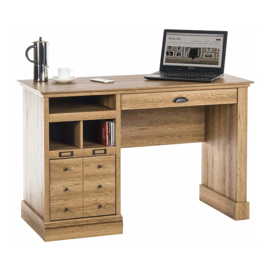
- Page 1 Teknik www.teknikoffice.co.uk Business or pleasure. Works both ways. Scribed Oak Desk 5414836 NOTE: THIS INSTRUCTION BOOKLET CONTAINS IMPORTANT SAFETY INFORMATION. PLEASE READ AND KEEP FOR FUTURE REFERENCE.
- Page 2 Table of Contents Assembly Tools Required Part Identifi cation No. 2 Phillips Screwdriver Tip Shown Actual Size Hardware Identifi cation Assembly Steps 6-32 Hammer Not actual size Français 33-36 Español 37-40 Short Screwdriver Safety 41-42 Warranty Skip the power trip. This time.
- Page 3 Part Identifi cation D266 D456 D455 D267 D707 Page 3...
- Page 4 Hardware Identifi cation å Screws are shown actual size. You may receive extra hardware with your unit. (EXTENSION SET SHOWN SEPARATED) EXTENSION EXTENSION 40CA CABINET RIGHT - 1 40CB CABINET LEFT - 1 RAIL - 2 SLIDE - 2 40CC DRAWER RIGHT - 1 40CD DRAWER LEFT - 1 SLIDE CAM - 2...
- Page 5 Hardware Identifi cation å Screws are shown actual size. You may receive extra hardware with your unit. BLACK 9/16" LARGE HEAD SCREW - 10 BLACK 1-7/8" FLAT HEAD SCREW - 8 GOLD 5/16" FLAT HEAD SCREW - 16 SILVER 1-1/8" FLAT HEAD SCREW - 8 BLACK 7/8"...
- Page 6 Step 1 Assemble your unit on a carpeted fl oor or on the empty å carton to avoid scratching your unit or the fl oor. To begin assembly, push a SAUDER TWIST-LOCK® å FASTENER (10F) into the large holes in the ENDS (A and B).
- Page 7 Step 2 Tap two MOLDING CONNECTORS (19F) into the notches å in the MOLDINGS (N, O, and P). Use your hammer to tap the MOLDING CONNECTORS (19F) into the notches in the MOLDINGS. Flat end Flat end Page 7...
- Page 8 Step 3 Carefully turn the MOLDINGS over. å Remember: Fasten the MOLDINGS (N, O, and P) to the TOP (E). Use å Righty tighty. eight SILVER 1-1/8" FLAT HEAD SCREWS (10S). Lefty loosey. SILVER 1-1/8" FLAT HEAD SCREW (8 used in this step) Long curved edge Page 8...
- Page 9 Step 4 Fasten the SKIRTS (L) to the ENDS (A and B). Use four å BLACK 1" PAN HEAD SCREWS (60S). BLACK 1" PAN HEAD SCREW (4 used in this step) Short unfi nished edge These edges should be even. Short unfi...
- Page 10 Step 5 Fasten the EXTENSION BLOCK (X) to the UPRIGHT (D). å Use two BLACK 7/8" FLAT HEAD SCREWS (31S) through the large holes in the EXTENSION BLOCK. Fasten a CABINET RIGHT (40CA) to the INNER RIGHT å END (A) and a CABINET LEFT (40CB) to the EXTENSION BLOCK (X ).
- Page 11 Step 6 Separate the EXTENSION SLIDES (AA) from the EXTENSION RAILS (Z) as shown in the upper diagram below. Be å prepared, the parts are greasy. Fasten an EXTENSION RAIL (Z) to the LEFT END (C) and UPRIGHT (D). Use four GOLD 5/16" FLAT HEAD SCREWS (3S). å...
- Page 12 Step 7 Fasten the OUTER RIGHT END (B) to the RIGHT å TOP MOLDING (P) on the TOP (E). Tighten two TWIST-LOCK® FASTENERS. How to use the SAUDER TWIST-LOCK ® FASTENER 1. Insert the dowel end of the FASTENER into the hole of the adjoining part.
- Page 13 Step 8 Fasten the MODESTY PANEL (G) to the INNER RIGHT END (A). å Use two BLACK 1-7/8" FLAT HEAD SCREWS (2S). Roller end Edge with TWIST-LOCK® FASTENERS r f a I S T w i t - L O ®...
- Page 14 Step 9 Fasten the INNER RIGHT END (A) to the RIGHT TOP å MOLDING (P) and the MODESTY PANEL (G) to the TOP (E). Tighten four TWIST-LOCK® FASTENERS. i t h K ® f a c L O C S u r I S T - E R S T E N...
- Page 15 Step 10 Slide the MOLDINGS* (T and V) onto the notched edges å of the ENDS (A and B). NOTE: The RIGHT FRONT MOLDING (T) is shorter å than the RIGHT REAR MOLDING (V). Do not confuse these MOLDINGS. *U.S. Patent No. 5,499,886 å...
- Page 16 Step 11 Slide the PLINTH (Y) onto the notched edge of the OUTER RIGHT END (B). Then, insert the SPRING CLIP (38G) into the å groove in the PLINTH to lock it into position. Fasten the UPRIGHT (D) to the TOP (E). Tighten two TWIST-LOCK® FASTENERS. å...
- Page 17 Step 12 Fasten the UPPER SHELF (H) to the UPRIGHT (D). å Tighten two TWIST-LOCK® FASTENERS. Now might be a good time to refresh NOTE: Once the UPPER SHELF (H) is fastened to your å your drink. unit, do not apply any pressure to the UPPER SHELF. It may break.
- Page 18 Step 13 Insert four METAL PINS (1R) into the DIVIDER (J). å Insert the METAL PINS (1R) in one end of the DIVIDER (J) into the å holes in the UPPER SHELF (H). NOTE: Do not apply any pressure to the UPPER SHELF. It may break. å...
- Page 19 Step 14 Fasten the LOWER SHELF (I) to the UPRIGHT (D). å Tighten two TWIST-LOCK® FASTENERS. NOTE: Be sure the METAL PINS in the DIVIDER (J) insert å into the holes in the LOWER SHELF (I). Do not apply any pressure to the SHELVES (H and I).
- Page 20 Step 15 Fasten two CARD HOLDERS (35M) to the LOWER SHELF å MOLDING (W). Use four SILVER 1/2" MACHINE SCREWS (38S). Fasten two METAL BRACKETS (4G) to the LOWER SHELF (I). Use å two BLACK 9/16" LARGE HEAD SCREWS (1S). NOTE: Be sure the BRACKETS are even with the edge of the å...
- Page 21 Step 16 NOTE: You may need to use a SHORT SCREWDRIVER in å this step. Fasten the LEFT END (C) to the SHELVES (H and I) and LEFT å TOP MOLDING (O). Tighten six TWIST-LOCK® FASTENERS. i t h o K ®...
- Page 22 Step 17 Fasten the BOTTOM (F) to the LEFT END (C) and å UPRIGHT (D). Use four BLACK 1-7/8" FLAT HEAD SCREWS (2S). NOTE: To fasten the BOTTOM, be sure to use the bottom å set of holes in the LEFT END and UPRIGHT. Fasten the SIDE SKIRTS (L) to the LEFT END (C) and å...
- Page 23 Step 18 Fasten three METAL BRACKETS (4G) to the LEFT END (C), å UPRIGHT (D), and BOTTOM (F). Use three BLACK 9/16" LARGE HEAD SCREWS (1S). NOTE: Be sure the BRACKETS are even with the edges å of the END, UPRIGHT, and BOTTOM. Fasten the BASE (U) to the LEFT END (C), UPRIGHT (D), å...
- Page 24 Step 19 Carefully turn your unit over onto its front edges. Lay the å Caution BACK (K) over your unit. Do not stand the unit upright without the Make equal margins along all four edges of the BACK (K). å BACK fastened.
- Page 25 Step 20 With the palm of your hand, tap the DRAWER BOTTOM D267 down into the groove. Groove fi n i s h r f a D455 D266 D266 D455 Start each screw a few turns before completely tightening any of them. D267 Be sure the PENCIL DRAWER BOTTOM inserts...
- Page 26 Step 21 Fasten the PENCIL DRAWER FRONT (M) to the PENCIL å DRAWER BOX FRONT (D455). Use two BLACK 7/8" LARGE HEAD SCREWS (17S). Fasten a PULL (70K) to the PENCIL DRAWER FRONT (M). å Use two GRAY 1-3/8" MACHINE SCREWS (39S) through the PENCIL DRAWER BOX FRONT, through the PENCIL DRAWER FRONT, and into the PULL.
- Page 27 Step 22 Fasten the DRAWER RIGHT (40CC) and DRAWER LEFT (40CD) å to the PENCIL DRAWER SIDES (D266 and D267). Use four GOLD 5/16" FLAT HEAD SCREWS (3S) through holes #2 and #4. Roller end D267 Roller end D266 (4 screws per drawer) GOLD 5/16"...
- Page 28 Step 23 The tabs should insert freely With the palm of your into the slots. Gently tilt the hand, tap the DRAWER DRAWER SIDES side to side BOTTOM down into until the tabs slip into the slots. the groove. D707 fi...
- Page 29 Step 24 Insert a SLIDE CAM (10A) into the FILE DRAWER å SIDES (D28 and D29). Fasten the EXTENSION SLIDES (AA) to the FILE DRAWER å SIDES (D28 and D29). Use four GOLD 5/16" FLAT HEAD SCREWS (3S) through holes #1 and #3. NOTE: The screw head in the CAM must be visible å...
- Page 30 Step 25 Push a FILE GLIDE (15B) onto the FILE RIGHT DRAWER å SIDE (D28). Slide the FILE RODS (8B) into the FILE GLIDE (15B) on the å FILE RIGHT DRAWER SIDE (D28). Slide another FILE GLIDE (15B) onto the other end of the å...
- Page 31 Step 26 Carefully stand your unit upright. å To insert the fi le drawer into your unit, line up the EXTENSION Pro Tip: Lift with your å SLIDES on the drawer with the EXTENSION RAILS on the unit legs. And, you know, your arms.
- Page 32 Step 27 To make adjustments to the fi le drawer, loosen SCREW #3 in the SLIDES a 1/4 turn, then turn the CAM clockwise or å counter-clockwise. Notice how the drawer raises or lowers as you turn the CAM. The higher the screw in the oblong hole, the higher your drawer front will be.
- Page 33 WARNING Please use your furniture correctly and safely. Improper use can cause safety hazards, or damage to your furniture or household items. Carefully read the following chart. Look out for: What can happen: How to avoid the problem: • Overloaded shelves and drawers. •...
Need help?
Do you have a question about the Scribed Oak Desk 5414836 and is the answer not in the manual?
Questions and answers