Advertisement
Quick Links
Advertisement

Related Manuals for Teknik Elstree Executive Desk 5426918


Summary of Contents for Teknik Elstree Executive Desk 5426918
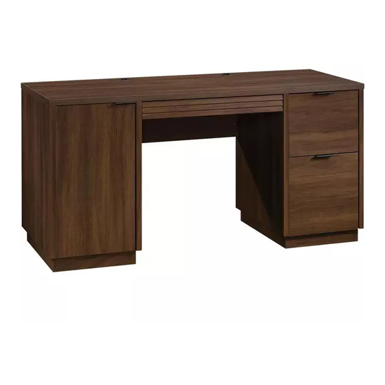
- Page 1 Teknik Sit and surf. Elstree Executive Desk Model 5426918...
- Page 2 Table of Contents Assembly Tools Required Part Identification No. 2 Phillips Screwdriver Tip Shown Actual Size Hardware Identification Assembly Steps 6-46 Hammer Not actual size Tape Measure Part Identification å Use this part identification to help identify the parts. RIGHT END (1) D139 LEFT DRAWER SIDE (1) KEYBOARD SIDE (2) LEFT END (1)
- Page 3 Now you know Part Identification our ABCs. å While not all parts are labeled, some of the parts will have a label or an inked letter on the edge to help distinguish similar parts from each other. Use this part identification to help identify similar parts. D133 D708 D139...
- Page 4 Hardware Identification RIGHT CABINET LEFT CABINET RIGHT DRAWER LEFT DRAWER RAIL - 1 RAIL - 1 SLIDE - 1 SLIDE - 1 40CA CABINET RIGHT - 1 40CB CABINET LEFT - 1 40CC DRAWER RIGHT - 1 40CD DRAWER LEFT - 1 (EXTENSION SET SHOWN SEPARATED) EXTENSION EXTENSION...
- Page 5 Hardware Identification å Screws are shown actual size. You may receive extra hardware with your unit. KEYBOARD PULL - 1 189K PULL - 3 GROMMET CAP - 3 CORD CLIP - 2 HIDDEN WIRELESS Qi COMPATIBLE METAL RUBBER GROMMET - 4 CHARGER by EGGTRONIC - Item 425905 PIN - 4 SLEEVE - 4...
- Page 6 Hardware Usage Guide HOW TO USE A TWIST-LOCK FASTENER ® Push a TWIST-LOCK® FASTENER 1. Insert the dowel end of the FASTENER into the into the large hole in the part. hole of the adjoining part. NOTE: The dowel end of the FASTENER must remain fully inserted in the hole of the adjoining part while locking the FASTENER.
- Page 7 Step 1 å Assemble your unit on a carpeted floor or on the empty carton to avoid scratching your unit or the floor. Some assembly å Push two TWIST-LOCK® FASTENERS (36F) into the large (and snacks) required. holes in the LEFT END (B) Do not tighten the TWIST-LOCK®...
- Page 8 Step 2 å Insert two WOOD DOWELS (15F) into the TOP (S). å Fasten the LEFT END (B) to the TOP (S). Tighten two TWIST-LOCK® FASTENERS. å NOTE: Be sure the WOOD DOWELS in the TOP insert into the LEFT END. S u r f a c i t h...
- Page 9 Step 3 å Push two TWIST-LOCK® FASTENERS (36F) into the large holes in the LEFT UPRIGHT (C). å Fasten the LEFT CABINET RAIL (U) to the LEFT UPRIGHT (C). Use two GOLD 5/16" FLAT HEAD SCREWS (3S). Do not tighten the TWIST-LOCK® FASTENERS in this step. GOLD 5/16"...
- Page 10 Step 4 å Slide a BACK (Q) into the grooves in the LEFT END (B) and TOP (S). Groove Groove Page 10...
- Page 11 Step 5 å Push four HIDDEN CAMS (1F) into a BOTTOM (E). Then, insert the metal end of a CAM DOWEL (2F) into each HIDDEN CAM. Do not tighten the HIDDEN CAMS in this step. Arrow Metal end Arrow Metal end Page 11...
- Page 12 Step 6 å Fasten the BOTTOM (E) to the LEFT END (B). Tighten two HIDDEN CAMS. å NOTE: Be sure the BACK (Q) inserts into the groove in the BOTTOM. Groove Page 12...
- Page 13 Step 7 å Insert two WOOD DOWELS (15F) into the TOP (S). å Fasten the LEFT UPRIGHT (C) to the TOP (S). Tighten two TWIST-LOCK® FASTENERS. å NOTE: Be sure the WOOD DOWELS in the TOP insert into the LEFT UPRIGHT. å...
- Page 14 Step 8 å Push four TWIST-LOCK® FASTENERS (36F) into the large holes in the MODESTY PANEL (F). å Fasten the MODESTY PANEL (F) to the LEFT UPRIGHT (C). Tighten two TWIST-LOCK® FASTENERS. Finished edge i t h ® f a c S u r - L O I S T...
- Page 15 Step 9 å Push two TWIST-LOCK® FASTENERS (36F) into the large holes in the RIGHT UPRIGHT (D) å Fasten the CABINET LEFT (40CB) to the RIGHT UPRIGHT (D). Use two GOLD 5/16" FLAT HEAD SCREWS (3S) through holes #1 and #4. Do not tighten the TWIST-LOCK®...
- Page 16 Step 10 å Separate the EXTENSION SLIDES (40MC) from the EXTENSION RAILS (40MA) as shown in the upper diagram below. Be prepared, the parts are greasy. å Fasten one EXTENSION RAIL (40MA) to the RIGHT UPRIGHT (D). Use two GOLD 5/16" FLAT HEAD SCREWS (3S) through holes #1 and #4.
- Page 17 Step 11 å Carefully turn the RIGHT UPRIGHT (D) over. å Fasten the RIGHT CABINET RAIL (T) to the RIGHT UPRIGHT (D). Use two GOLD 5/16" FLAT HEAD SCREWS (3S). å Insert two WOOD DOWELS (15F) into the edge of the RIGHT UPRIGHT (D).
- Page 18 Step 12 å Fasten the RIGHT UPRIGHT (D) to the TOP (S) and MODESTY PANEL (F). Tighten four TWIST-LOCK® FASTENERS. å NOTE: Be sure the WOOD DOWELS in the RIGHT UPRIGHT insert into the TOP. S u r f a c i t h I S T - L O...
- Page 19 Step 13 å Slide the remaining BACK (Q) into the grooves in the RIGHT UPRIGHT (D) and TOP (S). Groove Groove Page 19...
- Page 20 Step 14 å Push four HIDDEN CAMS (1F) into the remaining BOTTOM (E). Then, insert the metal end of a CAM DOWEL (2F) into each HIDDEN CAM. Do not tighten the HIDDEN CAMS in this step. Arrow Metal end Arrow Metal end Page 20...
- Page 21 Step 15 å Fasten the BOTTOM (E) to the RIGHT UPRIGHT (D). Tighten two HIDDEN CAMS. å NOTE: Be sure the BACK (Q) inserts into the groove in the BOTTOM. Groove Page 21...
- Page 22 Step 16 å Push two TWIST-LOCK® FASTENERS (36F) into the large holes in the RIGHT END (A). Side Step: Make nachos. (Optional, but å Insert two WOOD DOWELS (15F) into the RIGHT END (A). recommended.) å Fasten the CABINET RIGHT (40CA) to the RIGHT END (A). Use two GOLD 5/16"...
- Page 23 Step 17 å Fasten the remaining EXTENSION RAIL (40MA) to the RIGHT END (A). Use two GOLD 5/16" FLAT HEAD SCREWS (3S) through holes #1 and #4. å NOTE: For each EXTENSION RAIL, turn a SCREW into the hole shown in the enlarged diagram.
- Page 24 Step 18 å Fasten the RIGHT END (A) to the TOP (S). Tighten two TWIST-LOCK® FASTENERS. å NOTE: Be sure the WOOD DOWELS in the RIGHT END insert into the TOP. å NOTE: Be sure the BACK inserts into the groove in the RIGHT END.
- Page 25 Step 19 å Fasten two CORNER BRACKETS (31G) to one SHORT BRACE (H) exactly as shown. Use four BLACK 9/16" LARGE HEAD SCREWS (1S). å NOTE: Be sure the BRACKETS are even with the edge of the BASE. å Repeat this step for the remaining SHORT BASES (H). BLACK 9/16"...
- Page 26 Step 20 å Fasten two LONG BASES (J) to the CORNER BRACKETS on two SHORT BASES (H). Use eight BLACK 9/16" LARGE HEAD SCREWS (1S) through the CORNER BRACKETS and into the LONG BASES. å Fasten two METAL BRACKETS (4G) to the LONG BASES (J). Use two BLACK 9/16"...
- Page 27 Step 21 å Fasten the BRACKETS on the BASES (H and J) to the BOTTOMS (E). Use twenty BLACK 9/16" LARGE HEAD SCREWS (1S). å Push two CORD CLIPS (4P) into the holes in the TOP (S). å NOTE: The CORD CLIPS are used to hold the optional HIDDEN WIRELESS CHARGER cord.
- Page 28 Step 24 å Fasten two HINGES (14H) to the DOOR (P). Use four BLACK 1/2" FLAT HEAD SCREWS (11S). Now might be a good time to refresh å Fasten one PULL (189K) to the DOOR (P). Use two your drink. BLACK 9/16"...
- Page 29 Step 25 å Carefully stand your unit upright. Stop å Push the DOOR STOP (4I) into the hole in the LEFT UPRIGHT (C). å Before fastening the DOOR to your unit, be sure the mounting screw is against the stops as shown in the right diagram. If it isn't, Mounting loosen the adjusting screw and mounting screw to slide it against screw...
- Page 30 Step 26 å Refer to the enlarged diagram to identify the parts on the HINGE. å The DOOR may need some adjustments. Follow the text below to make needed adjustments. å DOOR ADJUSTMENTS: To adjust the DOOR from side to side (horizontal), turn the adjusting screw in or out.
- Page 31 Step 27 å Fasten the KEYBOARD SIDES (M) to the KEYBOARD SHELF (L). Use four BROWN 1-5/8" FLAT HEAD SCREWS (55S). å Fasten the KEYBOARD BACK (N) to the KEYBOARD SIDES (M). Use two BROWN 1-5/8" FLAT HEAD SCREWS (55S). å...
- Page 32 Step 28 å Fasten the KEYBOARD HINGES (12H) to the KEYBOARD FRONT (R). Use four SILVER 5/8" FLAT HEAD SCREWS (23S). å Fasten the KEYBOARD HINGES on the KEYBOARD FRONT (R) to the KEYBOARD SHELF (L). Use two SILVER 9/16" LARGE HEAD SCREW S (54S).
- Page 33 Step 29 å Fasten the DRAWER SLIDES (V and W) to the KEYBOARD SHELF (L). Use four BROWN 1" FLAT HEAD SCREWS (18S). å Fasten the PULL (21K) to the KEYBOARD SHELF (L). Use two BLACK 9/16" PAN HEAD SCREWS (51S). Roller end Roller end BLACK 9/16"...
- Page 34 Step 30 The tabs should insert freely With the palm of into the slots. Gently tilt the your hand, tap DRAWER SIDES side to side the DRAWER until the tabs slip into the slots. BOTTOM down U n fi n i s h into the groove.
- Page 35 Step 31 å Insert a SLIDE CAM (10A) into the FILE DRAWER SIDES (D87 and D88). å Fasten the EXTENSION SLIDES (40MC) to the FILE DRAWER SIDES (D87 and D88). Use four GOLD 5/16" FLAT HEAD SCREWS (3S) through holes #1 and #4. å...
- Page 36 Step 32 å Push a FILE GLIDE (6B) onto the FILE RIGHT DRAWER SIDE (D87). å Slide the FILE RODS (8B) into the FILE GLIDE (6B) on the FILE RIGHT DRAWER SIDE. å Slide another FILE GLIDE (6B) onto the other end of the FILE RODS (8B), then press this FILE GLIDE over the FILE LEFT DRAWER SIDE (D88).
- Page 37 Step 33 The tabs should insert freely With the palm of into the slots. Gently tilt the your hand, tap DRAWER SIDES side to side the DRAWER until the tabs slip into the slots. BOTTOM down U n fi into the groove. n i s h s u r f a c...
- Page 38 Step 34 å Insert a SLIDE CAM (10A) into the DRAWER SIDES (D133 and D139). å Fasten the DRAWER RIGHT (40CC) to the RIGHT DRAWER SIDE (D133) and the DRAWER LEFT (40CD) to the LEFT DRAWER SIDE (D139). Use four GOLD 5/16" FLAT HEAD SCREWS (3S) through holes #1 and #4.
- Page 39 Step 35 å Insert a GROMMET (10P) and GROMMET CAP (1P) into each large hole in the TOP (S). Almost time to å Insert a GROMMET (10P) and GROMMET CAP (1P) into the celebrate! With a nap. large hole towards the bottom of the LEFT UPRIGHT (C). å...
- Page 40 Step 36 å To insert the DRAWER (O) into your unit, tip the front of the drawer down and drop the rollers on the drawer behind the rollers on the unit. Lift the front of the drawer up and slide it into the unit. å...
- Page 41 Step 38 å To make adjustments to the DRAWER and FILE DRAWER, loosen SCREW #4 in the SLIDES a 1/4 turn, then turn the cam clockwise or counter-clockwise. Notice how the drawer raises or lowers as you turn the cam. By adjusting the drawer this way, it will help the DRAWER FRONT line up better when closed.
- Page 42 Step 39 å If you purchased and installed the HIDDEN WIRELESS Qi COMPATIBLE CHARGER by EGGTRONIC, plug it into an outlet in your wall. To charge your phone, place it on the WIRELESS CHARGING SPOT STICKER. See the next page, if needed, for troubleshooting.
- Page 43 WARNING Please use your furniture correctly and safely. Improper use can cause safety hazards, or damage to your furniture or household items. Carefully read the following chart. Look out for: What can happen: How to avoid the problem: • Overloaded shelves or drawers. •...
Need help?
Do you have a question about the Elstree Executive Desk 5426918 and is the answer not in the manual?
Questions and answers