Table of Contents
Advertisement
Quick Links
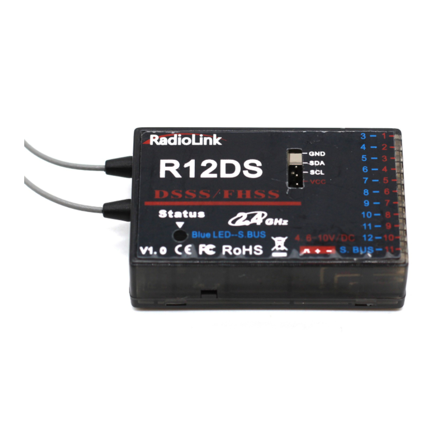
R12DS
(FHSS and DSSS Spread Spectrum)
Radiolink R12DS, 2.4G 12 channels receiver, DSSS and FHSS spread spectrum
working
synchronously, compatible with Radiolink transmitters AT9, AT9S,
AT9S Pro, AT10 and AT10II(AT9, AT9S, AT10 can upgrade to 12 channels just
upgrade by firmware, you can download the firmware from our website:
www.radiolink.com
AT10II is default 12 channels).
S-BUS and PWM signal possible working at the same time.
Two signal working mode:
1. PWM signal output working mode
Red LED indicates PWM signal output, 11 channels totally.
1
Advertisement
Table of Contents

Related Manuals for RadioLink R12DS


Summary of Contents for RadioLink R12DS
- Page 1 R12DS (FHSS and DSSS Spread Spectrum) Radiolink R12DS, 2.4G 12 channels receiver, DSSS and FHSS spread spectrum working synchronously, compatible with Radiolink transmitters AT9, AT9S, AT9S Pro, AT10 and AT10II(AT9, AT9S, AT10 can upgrade to 12 channels just upgrade by firmware, you can download the firmware from our website: www.radiolink.com...
- Page 2 2. S-BUS signal working mode: Receiver indicator is Blue (Purple) with 12 channels output in total and synchronously output SBUS and PWM signal. S-BUS signal channel (marked in BLUE) outputs 12 channels of S-BUS signal while PWM signal channels (CH3 to CH12 marked in BLUE) output PWM signals with 12 channels in total.
- Page 3 SBUS&PWM of 12 channels. How to bind to receiver and transmitter: 1. Put the transmitter and the receiver close to each other (about 50 centimeters) and power both on. 2. Switch on the transmitter and the RED led on R12DS will be on.
- Page 4 Note: Once upgraded with the latest firmware, the channel quantity of the transmitter (AT9/AT9S/AT10/AT10II) needs to be changed from 10 to 12 to work with R12DS, the 12-channel receiver. How to modify the channel setting on your radio: Press Mode button to enter BASIC MENU => Rotate the dial to select SYSTEM and Enter =>...
- Page 5 3. Large model aircraft may have some metal part interfering signal; in this case the antennas should be placed at both sides of the model. Then the best RF signal condition is obtained at any flying attitude. 4. The antennas must be kept away from conductive materials, such as metal and carbon.
- Page 6 After all of the above steps finished, now the program functions to assure it under control of transmitter with a right connection. Connect to telemetry module PRM-01 Connect to telemetry module PRM-03(the product in the middle is flight controller Mini Pix from Radiolink)
- Page 7 Specification: 11 channels for PWM signal output; 12 channels for SBUS&PWM signal output. Working voltage: 4.8-10V Working current: 38-45mA(input voltage: 5V) Size: 50*32*14.5MM (1.97"*1.26"*0.57") Weight: 14g (0.49oz) Receiver integrate telemetry sensor including signal strength and voltage. Support extended engine voltage telemetry module PRM-01 and module...
- Page 8 Pro/AT10/AT10II display when work with flight controller APM or PIX. 4096 section precision, 0.25us per section, servo anti-shake rudder. Control distance: about 4 kilometers air. (Maximum range tested in unobstructed areas free of interference and may vary depending on local regulations). More information please visit our website: http://www.radiolink.com...
Need help?
Do you have a question about the R12DS and is the answer not in the manual?
Questions and answers