Table of Contents
Advertisement
Quick Links
ONLINE ELECTRONICS LTD
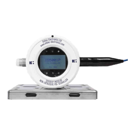
NON-INTRUSIVE PASSIVE ULTRASONIC
The ID5001P is a fully ATEX and IECEx certified, Exd flameproof,
non-intrusive pig signaller which detects, signals and logs the passage
of pigs at critical points along a pipeline both on land and offshore
Online Electronics Ltd
Online House
Blackburn Business Park
Woodburn Road, Blackburn
Aberdeen
AB21 0PS
UK
+44 (0)1224 714 714
ID5001P_5001_B00
www.online-electronics.com
sales@online-electronics.com
TOPSIDE PIG SIGNALLER
OPERATING MANUAL
Inline Services, LLC. 27731
Commercial Park Rd.
Tomball TX 77375
p. . 281.401.8142 | 888.973.0
e. . sales@inlineservices.com
w. . inlineservices.com
Page 0 of 36
Advertisement
Table of Contents

Summary of Contents for IK Online Electronics ID5001P
- Page 1 ONLINE ELECTRONICS LTD NON-INTRUSIVE PASSIVE ULTRASONIC TOPSIDE PIG SIGNALLER OPERATING MANUAL The ID5001P is a fully ATEX and IECEx certified, Exd flameproof, non-intrusive pig signaller which detects, signals and logs the passage of pigs at critical points along a pipeline both on land and offshore Online Electronics Ltd Online House Inline Services, LLC.
- Page 2 CR00570: Initial release. 23/05/19 CR00570: Section 2 & 9: Certificate numbers corrected. 14/01/20 Various graphics updated throughout (IK Rebranding). CR00264. Section 2: Specifications added for high temperature pipelines. Section 2: Specifications for battery options added. Section 5.3 & 5.4: High temp pipeline mounting instructions added.
-
Page 3: Table Of Contents
ONLINE ELECTRONICS LTD CONTENTS Page General Description ....................3 Specifications ...................... 4 Rules For Safe Operation ..................5 Operation ......................6 4.1. Turning On ...................... 6 4.2. Listening ......................7 4.3. Detection ......................7 4.4. Detection Algorithm ..................8 4.5. Single Button Menu Interface ................ -
Page 4: General Description
ONLINE ELECTRONICS LTD 1. GENERAL DESCRIPTION The ID5001P (Passive) pig signaller is a fully ATEX and IECEx certified, Exd flameproof, non- intrusive, pig signaller which detects, signals, and logs the passage of pigs at critical points along a pipeline both on land and offshore. The unit uses Passive (listening) techniques to detect pig passage events. -
Page 5: Specifications
ONLINE ELECTRONICS LTD 2. SPECIFICATIONS GENERAL External Supply ..................24.0VDC, <2.0W Battery type ..............7x Alkaline DURACELL ID1300 cells Battery life (Alkaline) in LISTENING/LOW POWER MODE at +20°C ......15 days Battery type ............... 7x Lithium SAFT LS33600 cells Battery life (Lithium) in LISTENING/LOW POWER MODE at +20°C ......30 days Housing Ambient Temperature range (External supply) .. -
Page 6: Rules For Safe Operation
ONLINE ELECTRONICS LTD 3. RULES FOR SAFE OPERATION ⚠ WARNING: The Special Conditions for Safe Use as detailed in section 10 CERTIFICATION APPENDIX must be followed. ⚠ WARNING: The purchaser of this equipment is responsible for the training and competence of operators and the way in which it is used. -
Page 7: Operation
ONLINE ELECTRONICS LTD 4. OPERATION Familiarise yourself with all of the rules for the safe operation of this equipment as described in section 3 RULES FOR SAFE OPERATION. 4.1. TURNING ON If powered from 24.0VDC power supply via the VEXT connection the unit will turn on COMPANY automatically as soon as power is applied. -
Page 8: Listening
ONLINE ELECTRONICS LTD 4.2. LISTENING While in LISTENING mode the unit continuously monitors the acoustic energy produced by the pipeline as it waits for a pig passage to occur. The unit is configured to recognize the unique sound signature produced by a pig as it passes the sensor. The unit uses the algorithm described in section 4.4 DETECTION ALGORITHM to detect a pig passage. -
Page 9: Detection Algorithm
ONLINE ELECTRONICS LTD 4.4. DETECTION ALGORITHM Below is a simplified flowchart for the ID5001P detection algorithm which is running while the unit is in LISTENING mode. Periodically calculate 100 bin FFT (200Hz per bin) Calculate Power In Band (PIB) between Lower Frequency bin (LF) and Upper Frequency bin (UF) Calculate Average Noise (AN) Calculate Average Value (AV) - Page 10 ONLINE ELECTRONICS LTD Below is a graphical representation a typical pig passage. PIB = Power In Band (between Lower Frequency bin (LF) and Upper Frequency bin (UF)) AN = Average Noise (PIB averaged over Average Noise Time (ANT) period in minutes) AV = Average Value (PIB averaged over Average Value Time (AVT) period in seconds) DL = Difference Level...
-
Page 11: Single Button Menu Interface
ONLINE ELECTRONICS LTD 4.5. SINGLE BUTTON MENU INTERFACE While LISTENING, the control button can be pressed to enter the menu interface. From the menu system the user can configure several parameters which are discussed in this section. When any menu screen is loaded the cursor will initially be located at the home position at the top right corner next to the page number to indicate that the BACK action will occur when the countdown expires. -
Page 12: Main Menu
ONLINE ELECTRONICS LTD 4.5.1. MAIN MENU The MAIN MENU is the initial entry point to the menu system. This menu consists of three pages as shown. DATE – Select this item to edit the system date. Ensure that a valid date is entered in DD/MM/YY format. TIME –... -
Page 13: Events Menu
ONLINE ELECTRONICS LTD 4.5.2. EVENTS MENU The EVENTS MENU allows the user to view and erase the EVENTS stored in the unit memory. ERASE VIEW TIMEOUT PRESS TIMEOUT PRESS PRESS TIMEOUT PRESS VIEW EVENTS – Selecting this item will allow the user to cycle through all logged EVENTS from oldest to newest. -
Page 14: System Info Menu
ONLINE ELECTRONICS LTD 4.5.3. SYSTEM INFO MENU The SYSTEM INFO MENU is largely read only and is primarily used to display certain system parameters to the user. SERIAL NO – READ ONLY – The unit serial number is configured at time of manufacture. FIRMWARE –... -
Page 15: Output Config Menu
ONLINE ELECTRONICS LTD 4.5.5. OUTPUT CONFIG MENU The OUTPUT CONFIG MENU allows the user to configure the output functionality of the unit. This menu consists of two pages as shown. OUTPUT DELAY – Select this item to modify the OUTPUT DELAY in HH:MM:SS format. -
Page 16: Detect Config Menu
ONLINE ELECTRONICS LTD 4.5.6. DETECT CONFIG MENU ADJUSTING THESE PARAMETERS WITHOUT FIRST CONSULTING ONLINE ELECTRONICS LTD MAY CAUSE THE UNIT TO MISS PIG PASSAGES OR GIVE FALSE DETECTIONS. The DETECT CONFIG MENU allows the user to configure the detection parameters for the unit. This menu consists of three pages as shown. -
Page 17: Rs485 Serial Interface
ONLINE ELECTRONICS LTD 4.6. RS485 SERIAL INTERFACE Communication to the ID5001P, via the RS485 interface, makes use of MODBUS RTU protocol. All the parameters available in the ID5001P menu system can also be accessed via the MODBUS interface. The serial interface should be configured as follows: 9600 baud, 8 data bits, 1 stop bit, no parity ⚠... - Page 18 ONLINE ELECTRONICS LTD HOLDING REGISTERS Upper Freq Bin (UF) 0 – 100 (200Hz/bin) Lower Freq Bin (LF) 0 – 100 (200Hz/bin) Number of Averages (NA) 1 – 50 Average Noise Time (ANT) 1 – 100 minutes Average Value Time (AVT) 1 –...
-
Page 19: Installation
ONLINE ELECTRONICS LTD 5. INSTALLATION ⚠ WARNING: The Special Conditions for Safe Use as detailed in section 10 CERTIFICATION APPENDIX must be followed at all times. Normally the unit is used to confirm whether or not a pig has passed a known point of interest on a pipeline such as a bend or valve. -
Page 20: Main Housing Pipeline Mounting
ONLINE ELECTRONICS LTD 5.3. MAIN HOUSING PIPELINE MOUNTING The pipeline mounted unit is supplied with a set of ratchet straps or steel banding as shown. If the pipeline surface temperature is expected to exceed the maximum permitted ambient temperature for the enclosure as per the tables in the Special Conditions for Safe Use within section 10 CERTIFICATION APPENDIX then the housing must NOT be fitted on the pipeline. -
Page 21: Sunshade Post Mounting
ONLINE ELECTRONICS LTD 5.5. SUNSHADE POST MOUNTING If the main housing is exposed to direct sunshine, then it is recommended that a sunshade is installed to prevent unnecessary heating of the unit which may shorten the lifespan of the equipment. Secure the post mount sunshade to the post as shown using the supplied M8 U-bolt / post / clamp / sunshade / 2x M8 washers / 2x M8 nuts. -
Page 22: Opening The Housing
ONLINE ELECTRONICS LTD 5.7. OPENING THE HOUSING The instructions detailed within the product certificate and section 10 CERTIFICATION APPENDIX of this manual must be followed at all times. ⚠ WARNING – DO NOT OPEN WHEN ENERGIZED. Using a 3mm AF Allen key loosen the M4 locking screw located at the 12 o’clock position on the REAR ENDCAP 6x full turns. -
Page 23: Battery Removal
ONLINE ELECTRONICS LTD 5.9. BATTERY REMOVAL The unit will have been configured at the time of manufacture for operation with either DURACELL INDUSTRIAL ID1300 alkaline OR SAFT LS33600 lithium cells. Depending on this configuration the unit will shut down when the battery voltage reaches 6.5V for alkaline or 17.0V for lithium. -
Page 24: External Connections
ONLINE ELECTRONICS LTD 5.10. EXTERNAL CONNECTIONS To access external connections, follow the steps below: The Special Conditions for Safe Use detailed in section 10 CERTIFICATION APPENDIX of this manual must be observed at all times. Remove the REAR ENDCAP as described in section 5.9 BATTERY REMOVAL of this manual. -
Page 25: Ex Connections
ONLINE ELECTRONICS LTD The default relay states can be reversed by setting the RELAY INVERT to ON using the menu system. The same thing can be achieved by simply swapping wiring between the NO and NC connections. 5.10.2. EX CONNECTIONS EX1, EX2 and EX3 are reserved for future use. -
Page 26: Current Loop Output
ONLINE ELECTRONICS LTD 5.10.8. CURRENT LOOP OUTPUT CL+ / CL- provide a current loop output for remote signalling. CL+ is connected to the current loop supply (in to unit). CL- is connected to the current loop return (out of unit). CL+ / CL- are isolated from 0V and all other connections. -
Page 27: Id5001P Config Software
ONLINE ELECTRONICS LTD 6. ID5001P CONFIG SOFTWARE The ID5001P Config Software is a Windows Forms Application used to monitor and configure ID5001P Pig Signallers over the RS485 serial interface. The software allows the user access to the following items remotely from a computer: Set system date and time •... -
Page 28: Software Installation
ONLINE ELECTRONICS LTD 6.1. SOFTWARE INSTALLATION Ensure that the software has been installed and tested in advance of when it will actually be required. The software supplied by Online Electronics requires the Microsoft .NET Framework to be installed on the host PC. Depending on which operating system is running on the host PC it may be necessary to upgrade to the latest version of the .NET framework to enable the correct installation of this software. -
Page 29: Using The Config Software
ONLINE ELECTRONICS LTD 6.2. USING THE CONFIG SOFTWARE ⚠ WARNING: Care should be taken when remotely controlling/configuring the unit as values set intentionally, or unintentionally, will immediately affect the operation of the ID5001P. E.g. enabling relay inversion, although a useful test, will cause the relay to switch and signal an event when no event is active. -
Page 30: Read/Write Tab
ONLINE ELECTRONICS LTD 6.2.2. READ/WRITE TAB The Read/Write tab is used to configure all the numerical parameters that can be both read from and written to. For a full description of each parameter refer to sections 4.5.5 Output Config Menu and 4.5.6 Detect Config Menu. -
Page 31: Booleans Tab
ONLINE ELECTRONICS LTD 6.2.4. BOOLEANS TAB The Booleans tab is used to configure all the boolean parameters that can be both read from and written to. For a full description of each parameter refer to sections 4.5.5 Output Config Menu and 4.5.6 Detect Config Menu. -
Page 32: Live View Window
ONLINE ELECTRONICS LTD 6.2.6. LIVE VIEW WINDOW The Live View window can be used to monitor the sensor readings in real time at a rate of 2Hz. This screen can be particularly useful for debugging and testing purposes and can provide additional understanding theory of operation of the unit. -
Page 33: Recommended Maintenance & Storage
ONLINE ELECTRONICS LTD 7. RECOMMENDED MAINTENANCE & STORAGE The instructions detailed within the product certificate and section 10 CERTIFICATION APPENDIX of this manual must be followed. Frequent inspections should be made. A schedule for maintenance checks should be generated according to the environment and frequency of use but should be regular enough to ensure the equipment continues to operate in the designed manner. -
Page 34: Disposal Of Unit
ONLINE ELECTRONICS LTD 8. DISPOSAL OF UNIT Online Electronics Ltd (OEL) takes its responsibilities under the WEEE Regulations extremely seriously and has taken steps to be compliant in line with our corporate and social responsibilities. In the UK, OEL has joined a registered compliance scheme WeeeCare (registration number WEE/MP3538PZ/SCH). -
Page 35: Warranty
ONLINE ELECTRONICS LTD 9. WARRANTY Online products are guaranteed for one year from the date of purchase. Goods should be returned transportation prepaid to Online Electronics Limited. There is no charge for parts or labour should any product require repair due to a manufacturing deficiency during the guarantee period. -
Page 36: Certification Appendix
ONLINE ELECTRONICS LTD 10. CERTIFICATION APPENDIX EQUIPMENT: ID5001P Pig Signaller MANUFACTURER: Online Electronics Ltd Online House Blackburn Business Park Woodburn Road Blackburn Aberdeen AB21 0PS Tel: +44 (0) 1224 714 714 Web: www.online-electronics.com NOTIFIED BODY NUMBER: 2812 ATEX CERTIFICATE: TRAC 13 ATEX 0008X IECEx CERTIFICATE: IECEx TRC 13.0006X MARKINGS:... - Page 37 ONLINE ELECTRONICS LTD External power and signals shall only be connected using suitable crimp ferrules to prevent accidental disconnection. Unused cable entries shall be sealed using suitable Ex certified blanking elements. The temperature at the cable entry point may exceed +70°C. Cables suitable for use at this temperature must be used.
Need help?
Do you have a question about the Online Electronics ID5001P and is the answer not in the manual?
Questions and answers