Table of Contents
Advertisement
Quick Links
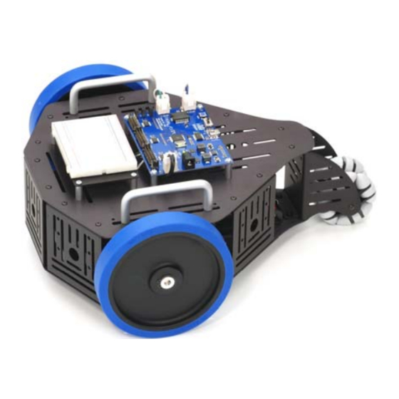
Stingray Robot (#28980)
The Stingray robot from Parallax Inc. provides a mid-size platform for a wide range of robotics projects and
experiments. The Propeller Robot Control Board is the brains of the system providing a multiprocessor
control system capable of performing multiple tasks at the same time. The Propeller chip provides eight 32-
bit processors each with two counters, its own 2 KB local memory and 32 KB shared memory. This makes
the Propeller a perfect choice for advanced robotics and the Stingray robot.
Features
•
Multicore Propeller chip based control board
•
Extra large EEPROM (64 KB) for storing additional
data
•
On-board 3.3 V & 5V switching power supply
•
5 V I/O translators to simplify interfacing to 5 V
sensors/devices
•
Integrated dual full bridge driver
•
Two DC spur gear motors
•
Two-wheel differential drive system with rear omni-
directional wheel
•
Multiple mounting locations for sensors, add-ons,
etc.
•
Free online Propeller Tool programming software for
Windows
and
(requires Win2K/XP/Vista, IE7 or higher, and USB port)
Key Specifications
•
Power requirements: 6 AA 1.2 V Rechargeable Batteries (not included)
•
Communication: USB A to Mini B Cable (included)
•
Operating temperature: 32 to 158 °F (0 to 70 °C)
•
Dimensions, assembled: 13" L x 10.9" W x 5.5" H (33 x 27.7 x 14 cm)
Prerequisites
This document covers assembly of your Stingray robot and testing of its motors. The Stingray is intended for
those with previous programming and electronics experience, specifically prior experience with the Propeller
chip microcontroller. The following resources are recommended for Propeller beginners:
•
Propeller Education Kit Labs: This educational text is a great way to get started with the Propeller.
It focuses on general Propeller programming and interfacing. The complete PDF and source code are
included in the Propeller Tool v1.2.6 or later Help file.
•
The Propeller Manual and Propeller Datasheet: These invaluable reference materials are also
included in the Propeller Tool v1.2.6 or later Help file.
•
The Propeller chip Forum (www.forums.parallax.com) At the top of the Propeller forum there is a
sticky thread titled "Propeller: Getting Started and Key Thread Index." This link contains a wealth of
information from Parallax and other sources for getting started with the Propeller.
Copyright © Parallax Inc.
Web Site: www.parallax.com
Forums: forums.parallax.com
Sales: sales@parallax.com
Technical: support@parallax.com
example
Stingray
source
Stingray Robot (#28980)
code
v1.1 10/6/2009 Page 1 of 26
Office: (916) 624-8333
Fax: (916) 624-8003
Sales: (888) 512-1024
Tech Support: (888) 997-8267
Advertisement
Table of Contents

Subscribe to Our Youtube Channel
Related Manuals for Parallax Stingray


Summary of Contents for Parallax Stingray
- Page 1 Tech Support: (888) 997-8267 Stingray Robot (#28980) The Stingray robot from Parallax Inc. provides a mid-size platform for a wide range of robotics projects and experiments. The Propeller Robot Control Board is the brains of the system providing a multiprocessor control system capable of performing multiple tasks at the same time.
-
Page 2: Bill Of Materials
USB A to Mini B Cable Assembly Instructions This section will guide you step-by-step as you assemble your Stingray robot. Each step will describe the parts and tools required and then the procedure to assemble them. Each step contains a CAD drawing as a visual aid to the instructions. -
Page 3: Additional Tools Required
Small pair of needle-nosed pliers optional, but make things easier) Safety first! Taking basic safety precautions is absolutely necessary when building the Stingray. The assembly process includes steps where there is the potential for injury. For example, you will be installing an o-ring which could fly off at high velocity if not installed properly. - Page 4 STEP 1: Chassis Assembly (lower) Parts Required • (1) Stingray Chassis Plate • (1) Stingray Tail Wheel Mount Plate • (5) Stingray Sensor Mount Plate • (16) Screw, Black, Button Socket Cap, • (2) Stingray Motor Mount Plate #4-40, ¼”...
-
Page 5: Step 2: Motor Installation
To distinguish them from the others you can see that the hex hole in the head of the M3 is larger and uses the 2 mm (larger) Hex Key. Motor Mount Plate Motors Right Side of Stingray Robot Front End of Stingray Robot Left Side of Stingray Robot... - Page 6 Left Motor Positive Terminal Connect to green wire Left Motor Left Motor Other Terminal Connect to white wire Green/White Motor Wire Assembly Copyright © Parallax Inc. Stingray Robot (#28980) v1.1 10/6/2009 Page 6 of 26...
-
Page 7: Step 4: Hub Installation
Repeat this procedure for the other motor. Hub Set Screws Wheel Hub Set Screw holes go over flat part of motor shaft Motor Shaft Wheel Hub Motor Copyright © Parallax Inc. Stingray Robot (#28980) v1.1 10/6/2009 Page 7 of 26... -
Page 8: Step 5: Front Wheel Installation
Repeat with other wheel. Note: A video clip demonstrating how to do install the Hub o-ring with needle nosed pliers is available for download on the Stingray product page on our website. O-ring Place o-ring over the hub and hold the back part of the ring in place. -
Page 9: Step 6: Tail Wheel Installation
(1) Multi-Directional Tail Wheel (Omni-Wheel) • 1/16” Hex Key (included) • (1) Stingray Tail Wheel Axle • (2) Screw, Black, Button Socket Cap, #4-40, ¼” Be sure the two halves of the Tail Wheel Assembly are joined. Slide the Tail Wheel Axle inside the Tail Wheel Assembly and place it between the fins of the Tail Wheel Mount Plate. -
Page 10: Step 7: Battery Holder Installation
Battery Holder Wires face left side of robot Screws Tail End of Washers Left Side of Stingray Robot Stingray Robot Screw, Black, Phillips Flat Head, #4-40, 1/4”” Copyright © Parallax Inc. Stingray Robot (#28980) v1.1 10/6/2009 Page 10 of 26... - Page 11 Use 6 AA 1.2 V Rechargeable Batteries Battery Retention Clip Battery Holder Copyright © Parallax Inc. Stingray Robot (#28980) v1.1 10/6/2009 Page 11 of 26...
- Page 12 • (8) Screw, Zinc, Pan Head, Phillips, #4-40, ¼” Position the Aluminum Handles over the Stingray Chassis Top Plate. The handles will only fit in the larger, outer slots on the left and right of the Chassis Plate. Using the Phillips end of the Parallax screwdriver, loosely attach the Aluminum Handles to the Chassis Plate using the #8-32 x 3/8”...
- Page 13 • 1/16” Hex Key (included) Place the Stingray Chassis Top Plate with the handles and standoffs installed over the robot. Bring the Motor Wires and Battery Holder Wire up through the large center hole as shown below. Line the Top Chassis Plate up with the holes in the Stingray Sensor Mount Plates.
- Page 14 Plate as shown by the cross-hatch area in the figure below. Breadboard, 3.19” L x 1.65” W Breadboard, 30 Row X 2 Column Do NOT stick breadboard assembly over mounting holes Breadboard Mounting Plate Copyright © Parallax Inc. Stingray Robot (#28980) v1.1 10/6/2009 Page 14 of 26...
- Page 15 Route the Battery Wire out from under the left side of the board, and the Motor Wires out from under the right side of the board as shown in the figure below. Using the Phillips end of the Parallax Screwdriver, attach the Propeller Robot Control Board to the standoffs using the #4-40 x ¼” screws.
- Page 16 STEP 13: Connecting Battery and Motor Wires Parts Required Tools Required • Assembled Stingray Robot • None Insert the Battery Wire plug into the matching socket just in front of the DC Barrel Jack on the Propeller Robot Control Board as shown in the figure below.
- Page 17 Completed Stingray Robot Left Side Tail End Right Side Front End Propeller Robot Control Board 1. Propeller P8X32A-Q44 7. USB Connector 13. 3-Position Power Switch 2. 64 KB EEPROM 8. Battery Pack Socket 14. Headers to I/O P0-P23 3. Socketed 5 MHz Crystal 9.
- Page 18 Propeller chip. A dual switching supply provides 3.3 V and 5 V @ up to 3 A each. The on-board dual full bridge driver makes it possible to directly drive the Stingray’s DC brushed gear motors with an extra motor controller.
- Page 19 PC. Data coming into the control board goes to P31 on the Propeller chip while data being sent comes from P30. Copyright © Parallax Inc. Stingray Robot (#28980) v1.1 10/6/2009 Page 19 of 26...
- Page 20 Battery Pack Socket [ 8 ] and Barrel Jack Connector [ 9 ] The Battery Pack Socket accepts the connector on the Stingray Battery Pack. The Barrel Jack Connector is for use with a 6-15 VDC wall-mount power supply, with a center positive 2.1 mm barrel connector.
- Page 21 I/O pins that you’re using the correct signal voltage (3.3 V) and that the I/O pin direction is set properly since there is no additional protection for the I/O lines when connecting directly to them. Jumper: Parallax #452-00009; 40-pin male/male header: Parallax #451-04001. Translator Enabled 8-pin bypass header and 2- pin translator header installed.
-
Page 22: Testing Communication
(3) Jumper Wire, F-M, 120 mm, 10-Pack Download and install the latest version of the Propeller Tool Software from the Downloads link at www.parallax.com/Propeller. Be sure to permit the installation/update of the FTDI USB drivers during installation. Be sure the power switch on the control board is set to ALL OFF. - Page 23 (marked R) and its voltage is set by the jumper immediately to the right of that group of headers. Download the example code from the Stingray product page at www.parallax.com. Load the program LED Test.spin into the Propeller Tool.
- Page 24 Brushed DC Spur-Gear Motors The Stingray robot was designed to be fast when needed and as such a method of locomotion was chosen to support this requirement. Servo motors used in many smaller robots are too slow and have too little load capacity for the Stingray.
-
Page 25: Testing The Motors
Slide the power switch on the control board to the second position (POWER ON/MOTORS ON). Select each program one at a time and download it to the Stingray robot by pressing the F10 key. Observe the results. Each motor should rotate forward for two seconds, stop for 2 seconds and rotate reverse for 2 seconds. -
Page 26: Additional Resources
Symptom: The motor starts to turn forward then stops, then starts to turn forward again. Check: The batteries may be running low. Try a fresh set of batteries. Additional Resources Resources for the Stingray such as example code are posted to the Stingray product page on our website. Go to our website at www.parallax.com and type the product number (28980) into the search box and click the Go button.
Need help?
Do you have a question about the Stingray and is the answer not in the manual?
Questions and answers