
Related Manuals for GAGEMAKER PG-6000


Summary of Contents for GAGEMAKER PG-6000
- Page 1 OPERATION MANUAL...
- Page 2 ©2009 Gagemaker, LP OMPG-600010-00...
-
Page 3: Table Of Contents
Product Information and Updates System Components Component List Setup Procedures Setting Up the PG-6000 Gage Zeroing the PG-6000 Gage Using Gage Blocks Zeroing the PG-6000 Gage Using the MIC TRAC Operating Procedures Inspecting Parts Care and Maintenance Maintenance Tips Warranty Information... - Page 5 Congratulations! Your decision to purchase a Gagemaker product above all others on the market demonstrates your confidence in our quality and workmanship. To ensure the high performance and operation of our product, we urge you to use the included reference materials.
-
Page 7: Introduction
(including uniformity of helix) taper, and roundness. The PG-6000 gages use thread rolls that are precision ground in matched sets to ANSI specifications to ensure maximum accuracy. The thread rolls seat in the thread form during inspection and reports actual measurement readings on the gage’s indicator. -
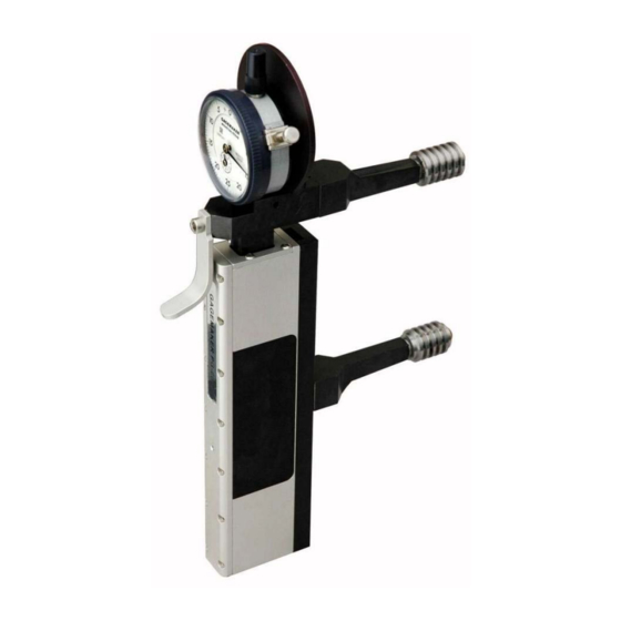
Page 8: System Components
System Components Take some time to become familiar with all the parts that make up the PG-6000 gage by reviewing the labeled diagram below. The part names are important for understanding the operating instructions. Component List Item Description Qty Item... -
Page 9: Setup Procedures
• Thread Disk for Windows software Setting up the PG-6000 gage, involves determining the thread roll type for your application and installing them on the gage. Entering some minimal thread information into the Thread Disk for Windows program will provide you with the proper type thread rolls, gage setting dimensions, and the gauging tolerances for your application. - Page 10 Setting Up the PG-6000 Gage (continued) 9. Using the 1/8” hex wrench, remove the lock screw and washer from each roll pin. 10. Clean the thread rolls and the roll pins on the gage to ensure they are free from debris.
- Page 11 Setting Up the PG-6000 Gage (continued) 12. Place the washer and lock screw on each roll pin. 13. Using the 1/8” hex wrench, tighten the lock screw. Eliminate any side to side movement of the thread roll, but make sure that the thread roll still rotates.
-
Page 12: Zeroing The Pg-6000 Gage Using Gage Blocks
• Gage block(s) PG-6000 gage To ensure consistent and accurate readings, the PG-6000 gage should be zeroed on gage blocks once during each shift, at a minimum. 1. Locate the gage setting dimensions previously printed from the Gagemaker screen in the Thread Disk for Windows software. - Page 13 .050” away from the upper arm to give the gage the proper preload. 7. Tighten the bent bolt to secure the adjuster arm in place. 8. Pull the retraction lever on the PG-6000 and insert the thread rolls between the gage block(s).
- Page 14 Zeroing the PG-6000 Gage Using Gage Blocks (continued) 9. Turn the indicator dial on the PG-6000 to align the needle with zero. 10. Tighten the indicator clamp. 11. Pull the retraction lever and remove the PG- 6000 from the gage block(s). Reposition the gage between the gage block(s) to verify the zero setting.
-
Page 15: Zeroing The Pg-6000 Gage Using The Mic Trac
• Setting dimensions (Thread Disk for Windows software) To ensure consistent and accurate readings, the PG-6000 gage should be zeroed on the MT- 3000 once during each shift, at a minimum. 1. Turn the coarse adjust knob counterclockwise to bring the flat face anvils together. - Page 16 Zeroing the PG-6000 Gage Using the MIC TRAC (continued) 10. Loosen the bent bolt on the PG-6000 gage to release the adjuster arm. 11. Slide the adjuster arm to position the gage between the flat face anvils until the thread rolls contact the flat face anvils.
- Page 17 Zeroing the PG-6000 Gage Using the MIC TRAC (continued) 14. Tighten the bent bolt on the PG-6000 gage to secure the adjuster arm. 15. Pull the retraction lever on the PG-6000 gage and place the thread rolls between the flat face anvils on the MT-3000.
- Page 18 Zeroing the PG-6000 Gage Using the MIC TRAC (continued) 17. Turn the indicator dial on the PG-6000 to align the needle with zero. 18. Tighten the indicator clamp. 19. Pull the retraction lever and remove the PG- 6000 from the MT-3000. Reposition the gage on the flat face anvils to verify the zero setting.
-
Page 19: Operating Procedures
Inspection report Part Inspecting parts using the PG-6000 involves placing the gage on a part in order to compare the nominal functional diameter of the gage to the actual functional diameter of the part. 1. After zeroing the PG-6000 gage, pull the retraction lever and position the lower thread roll in the threads of the part. - Page 20 Inspecting Parts (continued) 3. Ensure that the thread rolls on the PG-6000 fully engage with the threads in the part. 4. Sweep the PG-6000 gage back and forth to locate the largest indicator reading on the part. Use the gauging tolerances previously printed...
- Page 21 8. Use the first part you inspected as a control piece to verify repeatability. Mark the part at a location where it was inspected and record the deviation from zero. 9. During the inspection process, periodically place the PG-6000 on the control piece to verify the gage’s repeatability.
-
Page 22: Care And Maintenance
Keep the indicator face clean. Warranty Information GAGEMAKER warrants its products to be free from defects in material and workmanship for one year from the date of shipment. At our option, we will repair or replace any defective product upon return, prepaid, properly packed to our factory in Pasadena, Texas. - Page 23 NOTES:...
- Page 24 Gagemaker LP, P.O. Box 87709, Houston, Texas 77287-7709 712 East Southmore Ave., Pasadena, Texas 77502 Phone: 713-472-7360 Fax: 713-472-7241 Web site: www.gagemaker.com...
Need help?
Do you have a question about the PG-6000 and is the answer not in the manual?
Questions and answers