Table of Contents
Advertisement
Quick Links
Advertisement
Table of Contents

Related Manuals for GAGEMAKER LG-5003


Summary of Contents for GAGEMAKER LG-5003
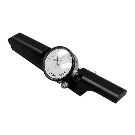
- Page 1 LG-5003 Lead Gage OP ER ATI ON M ANUAL...
- Page 2 Lead Gage Operation Manual Model LG-5003 ©2014 Gagemaker, LP Copyright © 2014 Gagemaker. All rights reserved...
-
Page 3: Table Of Contents
Technical Support Product Information and Updates Parts List Setup Procedures Setting Up the Lead Gage Zeroing the Lead Gage Operating Procedures Inspecting Parts Care and Maintenance Replacing the Indicator Maintenance Tips Warranty Information Copyright © 2014 Gagemaker. All rights reserved... -
Page 4: Introduction
This unique design does not require sweeping to obtain measurements. By removing the third contact point, the LG-5003 is easily converted to a conventional lead gage, which uses two contact points and requires sweeping the gage to obtain the shortest lead dimension. -
Page 5: Parts List
Flat contact point P-500 Nose cap screw LG-5003-A7 Contact point* T072* Split bushing LG-5003-A8 Indicator** 80-0403** * T072 contact points are shipped standard, but other contact points are available. **A higher resolution indicator is available. Copyright © 2014 Gagemaker. All rights reserved... -
Page 6: Setup Procedures
Buttress Casing - Lead 0.062” T062 API Tubing and Line Pipe 0.057” T057 API Line Pipe 0.050” 11 ½ T050 API Line Pipe 0.041” T041 API Line Pipe 0.032” T032 API Line Pipe 0.021” T021 Copyright © 2014 Gagemaker. All rights reserved... -
Page 7: Setting Up The Lead Gage
(refer to tables on previous page). 3. Verify the diameter of the contact point ball using calipers or a micrometer. 4. Install a contact point into the moveable holder at the front of the gage. Copyright © 2014 Gagemaker. All rights reserved... - Page 8 5. Install the remaining two contact points into the proper holes at the rear of the gage. 6. Once installed, insert a paper clip into the hole in each contact point and tighten. Copyright © 2014 Gagemaker. All rights reserved...
-
Page 9: Zeroing The Lead Gage
3½” - 6 ⅝” H-90 3½ LS-1011 7” - 8 ⅝” H-90 3½ LS-1012 2 ⅜” - 3½” Slimline H-90 1¼ LS-1013 Straight Threads, 1-5 pitch, 4” length LS-5001 Straight Threads, 6-18 pitch, 4” length LS-5002 Copyright © 2014 Gagemaker. All rights reserved... - Page 10 For Non-V threads, pull the lead gage toward the load flank of the groove in the standard. For V threads, be sure the contact points touch both flanks of the groove in the standard. Copyright © 2014 Gagemaker. All rights reserved...
- Page 11 Zeroing the Lead Gage (continued) 4. With the two contact points properly seated in the grooves of the standard, turn the indicator dial to align the needle with zero. 5. Tighten the indicator clamp. Copyright © 2014 Gagemaker. All rights reserved...
-
Page 12: Operating Procedures
1. Seat the rear contact points into the thread next to the first scratch on the part (or first full thread). 2. Rock the gage forward and seat the moveable contact point into the thread. Copyright © 2014 Gagemaker. All rights reserved... - Page 13 Take note of the reading. 5. Record the maximum lead error on an inspection report. 6. During the inspection process, periodically verify the gage’s repeatability by placing it on the lead standard. Copyright © 2014 Gagemaker. All rights reserved...
-
Page 14: Care And Maintenance
2. Using a 5/64” hex wrench, loosen the indicator set screw on the nose piece of the gage, and remove the indicator. 3. Remove the flat contact point from the indicator stem. Copyright © 2014 Gagemaker. All rights reserved... - Page 15 7. Insert the new indicator into nose piece of the Set Screw gage. Be sure the split in the sleeve is at a 90º angle to the indicator set screw. Sleeve Split Copyright © 2014 Gagemaker. All rights reserved...
- Page 16 8. Using a 5/64” hex wrench, tighten the indicator set screw on the gage’s nose piece. 9. Replace the gage handle and tighten the cap screws with the 7/64” hex wrench. 10. Loosen the indicator set screw to release the indicator. Copyright © 2014 Gagemaker. All rights reserved...
- Page 17 –10 to give the gage the proper preload. 14. Turn the ⅛” hex wrench counter clockwise until the indicator needle aligns with zero. Pull back slightly on the indicator if necessary. Copyright © 2014 Gagemaker. All rights reserved...
- Page 18 15. Using the 5/64” hex wrench, tighten the indicator set screw. 16. Remove the lead gage from the lead standard. 17. Place the gage back on the standard to verify that there is a .010” preload. Copyright © 2014 Gagemaker. All rights reserved...
-
Page 19: Maintenance Tips
Gagemaker warrants its products to be free from defects in material and workmanship under normal operating conditions for 12 months from the date of shipment. This warranty is limited to repairing, or at Gagemaker’s option, replacing any product which is proven to have been defective at the time it was shipped and/or suffered damage during shipping;... - Page 20 Gagemaker, LP, P.O. Box 87709, Houston, Texas 77287-7709 712 East Southmore Ave., Pasadena, Texas 77502 Phone: 713-472-7360 Fax: 713-472-7241 Web site: www.gagemaker.com...
Need help?
Do you have a question about the LG-5003 and is the answer not in the manual?
Questions and answers