
Related Manuals for GAGEMAKER PD-6001


Summary of Contents for GAGEMAKER PD-6001
- Page 1 OPERATION MANUAL...
- Page 2 ©2009 Gagemaker, LP OMPD-600110-00...
-
Page 3: Table Of Contents
Product Information and Updates System Components Component List Setup Procedures Setting Up the PD-6001 Gage Zeroing the PD-6001 Gage Using Gage Blocks Zeroing the PD-6001 Gage Using the MIC TRAC Operating Procedures Inspecting Parts Care and Maintenance Maintenance Tips Warranty Information... - Page 5 Congratulations! Your decision to purchase a Gagemaker product above all others on the market demonstrates your confidence in our quality and workmanship. To ensure the high performance and operation of our product, we urge you to use the included reference materials.
-
Page 7: Technical Support
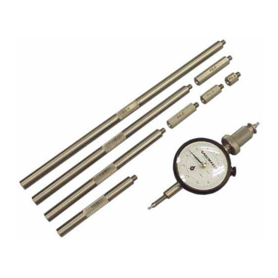
+.0002” and measurements are based on the proven three wire inspection method and technique. The PD-6001 includes eight extension rods that attach to the gage and allow measuring a range of diameters up to 24”. Using different combinations of the extension rods and the fine adjustment knob will give the PD-6001 gage the proper internal dimension for the part being inspected. -
Page 8: Component List
System Components Take some time to become familiar with all the parts that make up the PD-6001 gage by reviewing the labeled diagram below. The part names are important for understanding the operating instructions. Component List Item Description Qty Item... -
Page 9: Setting Up The Pd-6001 Gage
Paper clip Thread Disk for Windows software Setting up the PD-6001 gage, involves determining the contact point type for your application and installing them on the gage. Entering some minimal thread information into the Thread Disk for Windows program will provide you with the proper type contact points, gage setting dimensions, and the gauging tolerances for your application. - Page 10 Setting Up the PD-6001 Gage (continued) 9. Inspect the contact points to ensure that they are not damaged. 10. Screw one of the contact points into the threaded hole in the indicator shaft. Be sure that the contact point is fully...
- Page 11 Setting Up the PD-6001 Gage (continued) 11. Using the PD-6001 Gage Extension Rod Selection Chart, locate the minimum and maximum diameter range for the part. 12. Select the proper extension rod(s) to be attached to the PD-6001 to give the gage the proper internal dimension.
- Page 12 Setting Up the PD-6001 Gage (continued) 13. Attach the extension rod(s) to the fine adjustment knob on the PG-6001. 14. Attach the contact point adapter to the extension rod(s). 15. Attach the contact point to the adapter. Do not use pliers to tighten the contact points, as damage may result.
-
Page 13: Zeroing The Pd-6001 Gage Using Gage Blocks
· Gage block(s) PD-6001 gage To ensure consistent and accurate readings, the PD-6001 gage should be zeroed on a gage block once during each shift, at a minimum. 1. Locate the gage setting dimensions previously printed from the Gagemaker screen in the Thread Disk for Windows software. - Page 14 Zeroing the PD-6001 Gage Using Gage Blocks (continued) 6. To secure the position of the PD-6001, turn the fine adjustment lock. 7. While maintaining pressure between the lower contact point and gage block, sweep the upper contact point to locate the smallest indicator reading.
- Page 15 Zeroing the PD-6001 Gage Using Gage Blocks (continued) 9. Tighten the indicator clamp. 10. Remove the PD-6001 from the gage block(s). Reposition the gage on the gage block(s) to verify the zero setting. Note: Note the position of the small revolution counter on the indicator before removing the gage.
-
Page 16: Zeroing The Pd-6001 Gage Using The Mic Trac
· · Setting dimensions (Thread Disk for Windows software) To ensure consistent and accurate readings, the PD-6001 gage should be zeroed on the MIC TRAC once during each shift, at a minimum. 1. Turn the coarse adjust knob counterclockwise to bring the flat face anvils together. - Page 17 12. To give the gage the proper preload, turn the fine adjustment knob until the needle on the indicator dial makes one complete revolution. 13. To secure the position of the PD-6001, turn the fine adjustment lock. 14. Remove the gage from the MT-3000.
- Page 18 16. Turn the indicator dial on the PD-6001 to align the needle with zero. 17. Tighten the indicator clamp. 18. Remove the PD-6001 from the MT-3000.
- Page 19 Zeroing the PD-6001 Gage Using the MIC TRAC (continued) 19. Remove the PD-6001 gage from the MT-3000. 20. Set a frequency for verifying the zero setting of all gages. As a minimum, the PD-6001 gage should be zeroed on the MIC TRAC once...
-
Page 21: Inspecting Parts
Inspection report Part Inspecting parts using the PD-6001 involves placing the gage on a part in order to compare the nominal pitch diameter of the gage to the actual pitch diameter of the part. 1. After zeroing the PD-6001 gage, position the upper contact point in the second thread of the part. - Page 22 Inspecting Parts (continued) 4. Ensure that the contact points on the PD-6001 fully engage with the threads in the part. 5. Sweep the PD-6001 gage to locate the largest indicator reading on the part. Use the gauging tolerances, previously printed from the...
- Page 23 8. Use the first part you inspected as a control piece to verify repeatability. Mark the part at a location where it was inspected and record the deviation from zero. 9. During the inspection process, periodically place the PD-6001 on the control piece to verify the gage’s accuracy.
-
Page 24: Maintenance Tips
12 months from the date of shipment. This warranty is limited to repairing, or at Gagemaker’s option, replacing any product which is proven to have been defective at the time it was shipped and/or suffered damage during shipping, provided buyer has given Gagemaker written notice of any such claimed defect within 15 days of receipt. - Page 25 Notes:...
- Page 26 Notes:...
- Page 27 Notes:...
- Page 28 Gagemaker, LP, P.O. Box 87709, Houston, Texas 77287-7709 712 East Southmore Ave., Pasadena, Texas 77502 Phone: 713-472-7360 Fax: 713-472-7241 Web site: www.gagemaker.com...
Need help?
Do you have a question about the PD-6001 and is the answer not in the manual?
Questions and answers