GAGEMAKER MIC TRAC MT-3000 Operation Manual
Mic trac
Hide thumbs
Also See for MIC TRAC MT-3000:
- Operation manual (32 pages) ,
- Manual (12 pages) ,
- Manual (20 pages)
Table of Contents
Advertisement
Advertisement
Table of Contents

Subscribe to Our Youtube Channel
Related Manuals for GAGEMAKER MIC TRAC MT-3000


Summary of Contents for GAGEMAKER MIC TRAC MT-3000
- Page 1 M T-3000 M I C TR AC OP ER ATI ON M ANUAL...
- Page 2 MIC TRAC Operation Manual Model MT-3000 ©2014 Gagemaker, LP Copyright © 2014 Gagemaker. All rights reserved...
-
Page 3: Table Of Contents
Changing from Internal to External measurement Mode Changing the Zero Setting Operating Procedures Measuring Parts with Force-Lok Troubleshooting Guide Care and Maintenance Maintenance Tips Maintenance Note Safety Tips Warranty Information Product Return or Calibration Process Technical Information Copyright © 2014 Gagemaker. All rights reserved... - Page 4 MIC TRAC Operation Manual Model MT-3000 Copyright © 2014 Gagemaker. All rights reserved...
- Page 5 The MIC TRAC addresses gage setting and calibration issues that were never possible before. All it takes is a little imagination. But, for those who don’t have time to imagine, Gagemaker provides gages and fixtures to accompany the MIC TRAC to make your job easier and more precise.
-
Page 6: Introduction
Proper positioning of the gage improves the accuracy of the calibration and provides more consistent results. Refer to the MIC TRAC MT-3000 Calibration Reference Cards and the Gage Calibration Setup Poster for information about using the CAL-PAK fixtures. -
Page 7: Unpacking And Handling
4. For removing the unit, there are four lifting lugs attached to the sides of the MIC TRAC. 5. Secure two 36" X ¾" durable lifting straps around the lifting lugs on each side. Copyright © 2014 Gagemaker. All rights reserved... - Page 8 Gagmaker is not responsible for any damages incurred during return shipment due to poor packing. Copyright © 2014 Gagemaker. All rights reserved...
-
Page 9: Returning The Mic Trac
If the unit is returned in any container other than the original shipping carton, there will be a charge for carton replacement when the gage is returned to you. Gagemaker is not responsible for any damages incurred during return shipment due to poor packing. -
Page 10: Parts List
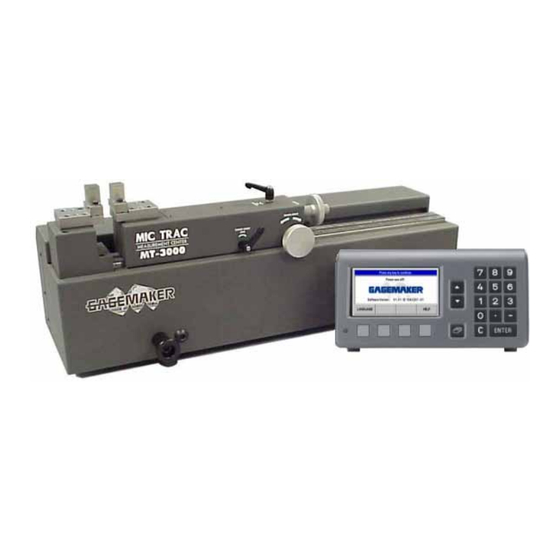
MIC TRAC Base Unit DRO Cable Receiver Pads Flat Face Anvils (TF-1F Blocks) Movable Carriage Fine Adjust Lock Fine Adjust Knob Coarse Adjust Knob Coarse Adjust Lock Lifting Lugs Force Cable (option with Force-Lok units only) Copyright © 2014 Gagemaker. All rights reserved... -
Page 11: Mic Trac Part Descriptions
Do not attempt to turn the coarse adjust knob when the lock is secured. Fine Adjust Lock Secures the right receiver pad during measurement. Do not attempt to turn the fine adjust knob when the lock is secured. Copyright © 2014 Gagemaker. All rights reserved... -
Page 12: Digital Readout (Dro) Front Panel
The arrow keys move the selection field into the display, when applicable. Keypad The keypad is used to enter data and passcodes, when required. Softkeys The softkeys allow you to select items that display on the screen directly above each button. Copyright © 2014 Gagemaker. All rights reserved... -
Page 13: Digital Readout (Dro) Rear Panel
Plug the connector in and secure it in place with the screws. X1 – Scale Connector The X1 port connects to the internal scale of the MIC TRAC. Plug the 15-pin plug from the base unit into this port. Copyright © 2014 Gagemaker. All rights reserved... - Page 14 Digital Readout (DRO) Rear Panel (continued) X32/X31 Two serial ports for data transfer: X31: RS-232-C/V.24 X32: USB Type B (UART) Serial Port: Switching inputs and outputs at D-sub connection. Ground Terminal Protective earth ground terminal. Copyright © 2014 Gagemaker. All rights reserved...
-
Page 15: Digital Readout (Dro) Screen Features
The message line provides information about the required data input or procedures, which provide support with using the position display. If errors or warnings occur, they display in red letters on the message line. Clear the message with the C key. Copyright © 2014 Gagemaker. All rights reserved... - Page 16 Switches the position display to the displayed unit of measure. The inch [mm] selected unit of measure is shown in the status bar. INTERNAL ZERO Zeroes the readout for external or internal measurements. [EXTERNAL ZERO] Copyright © 2014 Gagemaker. All rights reserved...
- Page 17 1538 required). COUNTING Opens the menu to change counting direction of axis X1 DIRECTION (correct passcode 1538 required). FORCE-LOK ON/OFF Turns the measuring force option on and off. HELP Calls the integrated help system. Copyright © 2014 Gagemaker. All rights reserved...
-
Page 18: Setup Procedures
1. Remove the four lugs with a 3/8" hex wrench. 2. Replace each lug bolt with one of four button head cap screws, using a 5/16" hex wrench. Copyright © 2014 Gagemaker. All rights reserved... -
Page 19: Attaching Cables To The Digital Readout
Note: Do not force any electrical connections together. Always check alignment prior to joining any connection. 3. For the 3000F Models Only, plug the Force-Lok cable into the X2 port on the rear panel of the DRO. Copyright © 2014 Gagemaker. All rights reserved... - Page 20 240V operation. 6. Turn the DRO on using the ON/OFF switch. The display on the front panel should be illuminated. If the display does not respond, refer to the Troubleshooting Guide in this manual. Copyright © 2014 Gagemaker. All rights reserved...
-
Page 21: Mounting The Flat Face Anvils
5. Repeat the same process with the right flat face anvil. 6. Alignment and parallelism may be verified by measuring a precision contact ball at various locations about the face of the anvil. Copyright © 2014 Gagemaker. All rights reserved... -
Page 22: Connecting The Optional Printer
1. Plug the printer cable into the proper port on the rear of the DRO. Refer to the printer manufacturer’s instructions for communication details. 2. Ports available for communication: · RS-232-C/V.24 · USB Type B (UART · Serial Copyright © 2014 Gagemaker. All rights reserved... -
Page 23: Zeroing The Mic Trac Without Force-Lok
Internal Zero key on page 1 of the display. 4. With the anvils together, press the softkey below the Internal Zero key. The display will read 0.00000. 5. Adjust the MIC TRAC to the desired location. Copyright © 2014 Gagemaker. All rights reserved... -
Page 24: Zeroing The Mic Trac With Force-Lok
Note: You may re-zero the unit at any time by pressing to locate the Internal [External] Zero key on page 1 of the display. Press the softkey below Internal Zero and when the display reads 0.00000, bring the anvils together again. Copyright © 2014 Gagemaker. All rights reserved... -
Page 25: Changing The Mic Trac With Force-Lok Measuring Force
0.00000 and the gaging force will be set to the new pressure. This new pressure setting will remain the default setting until it is changed, even if the power is turned off. Copyright © 2014 Gagemaker. All rights reserved... -
Page 26: Changing From Internal To External Measurement Mode
Internal to External mode. The display will change from 1.5000 in external mode to 0.0000 in internal mode. The default value of 1.5000 for External mode is the outside dimension of the standard flat face anvils. Copyright © 2014 Gagemaker. All rights reserved... -
Page 27: Changing The Zero Setting
3. Re-zero the MIC TRAC using the procedures in 1.5000S the Zeroing the MIC TRAC section of this manual. Note: This new external zero setting will remain the default setting until it is changed, even if the power is turned off. Copyright © 2014 Gagemaker. All rights reserved... -
Page 28: Operating Procedures
1/16" of the part. Tighten the coarse adjust lock. 3. Still holding the part, turn the fine adjust knob until the right flat face anvil makes contact with the part and the light on the DRO turns on. Copyright © 2014 Gagemaker. All rights reserved... - Page 29 Model MT-3000 Measuring Parts with Force-Lok (continued) 4. When the is illuminated, the readout freezes on the measured value. If a printer is attached, the DRO automatically sends the measurement data to the printer. Copyright © 2014 Gagemaker. All rights reserved...
-
Page 30: Troubleshooting Guide
Brake may be locked with a load neutral position. applied to moving anvil. DRO continues to display The unit may have failed a self- Contact Gagemaker for help. “CALIBRATION ERROR” diagnostic check at power up. Copyright © 2014 Gagemaker. All rights reserved... -
Page 31: Care And Maintenance
When shipping your MIC TRAC, for whatever reason, use the shipping carton and packing material that came with the unit to minimize the risk of damage. Gagemaker will assume no responsibility for goods damaged during return shipment due to improper packaging. -
Page 32: Warranty Information
Products Requiring Repair or Calibration Return Process The MIC TRAC MT-3000 is precision calibrated at the factory traceable to NIST. To ensure that the MIC TRAC is providing accurate measurements, the unit should be calibrated annually, based on frequency of use and operating conditions. -
Page 33: Technical Information
32° to 100° F (0° to 40° C) á The recommended temperature for any precision metrology, if a high degree of accuracy is required, is 68 F. All certifications should be made at 68 F. Copyright © 2014 Gagemaker. All rights reserved... - Page 34 MIC TRAC Operation Manual Model MT-3000 Copyright © 2014 Gagemaker. All rights reserved...
- Page 36 Gagemaker, LP, P.O. Box 87709, Houston, Texas 77287-7709 712 East Southmore Ave., Pasadena, Texas 77502 Phone: 713-472-7360 Fax: 713-472-7241 Email: gagemaker@gagemaker.com Web site: www.gagemaker.com...
Need help?
Do you have a question about the MIC TRAC MT-3000 and is the answer not in the manual?
Questions and answers