Table of Contents
Advertisement
Quick Links
Advertisement
Table of Contents

Related Manuals for GAGEMAKER LG-6001


Summary of Contents for GAGEMAKER LG-6001
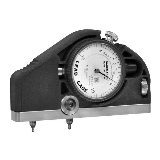
- Page 1 LG-6001 Lead Gage OP ER ATI ON M ANUAL...
-
Page 2: Lead Gage Operation Manual Model Lg
Lead Gage Operation Manual Model LG-6001 ©2016 Gagemaker, LP OMLG60014-16 Copyright © 2016 Gagemaker. All rights reserved... -
Page 3: Table Of Contents
Setting Up the Lead Gage Adjusting the Lead Gage Zeroing the Lead Gage Operating Procedures Inspecting Parts Care and Maintenance Replacing the Indicator Maintenance Tips Warranty Information Products Requiring Repair or Calibration Return Process Copyright © 2016 Gagemaker. All rights reserved... - Page 4 Lead Gage Operation Manual Model LG-6001 Copyright © 2016 Gagemaker. All rights reserved...
- Page 5 Lead Gage Operation Manual Model LG-6001 Congratulations! Your decision to purchase a Gagemaker product above all others on the market demonstrates your confidence in our quality and workmanship. To ensure the high performance and operation of our product, we urge you to use the included reference materials.
- Page 6 Lead Gage Operation Manual Model LG-6001 Copyright © 2016 Gagemaker. All rights reserved...
-
Page 7: Introduction
API Threads in the Setup Procedures section of this manual for contact point model numbers). Gagemaker’s lead gage, Model LG-6001, uses two contact points to inspect thread lead. One fixed contact point at the rear of the gage and one moveable contact point at the front of the gage provide complete stability when taking thread lead measurements. - Page 8 Lead Gage Operation Manual Model LG-6001 Copyright © 2016 Gagemaker. All rights reserved...
-
Page 9: Parts List
9 Adjustment Screw 4-2-825 19 SSSCP #4-40 X 3/16” 12-0-145 10 Back Brake Washer 4-2-826 20 SBHCS #8-32 X 9/16” 12-0-203 *T072 contact points are shipped standard, but other contact points are available. Copyright © 2016 Gagemaker. All rights reserved... -
Page 10: Setup Procedures
Buttress Casing - Lead 0.062” T062 API Tubing and Line Pipe 0.057” T057 API Line Pipe 0.050” 11 ½ T050 API Line Pipe 0.041” T041 API Line Pipe 0.032” T032 API Line Pipe 0.021” T021 Copyright © 2016 Gagemaker. All rights reserved... - Page 11 (refer to tables on the previous page). 3. Verify the diameter of the contact point ball using calipers or a micrometer. 4. Install a contact point into the moveable holder at the front of the gage. Copyright © 2016 Gagemaker. All rights reserved...
- Page 12 (from Step 1). 6. Install the contact point into the fixed holder at the rear of the gage. 7. Once installed, insert a paper clip into the hole in each contact point and tighten. Copyright © 2016 Gagemaker. All rights reserved...
-
Page 13: Adjusting The Lead Gage
3. Continue rotating the adjustment knob until the indicator needle makes one full revolution of preload. 4. Lock the indicator knob. Copyright © 2016 Gagemaker. All rights reserved... - Page 14 Lead Gage Operation Manual Model LG-6001 Adjusting the Lead Gage (continued) 5. Tighten the screw on the front of the gage with a hex wrench. Copyright © 2016 Gagemaker. All rights reserved...
-
Page 15: Zeroing The Lead Gage
2 ⅞” - 3 ½”, 4½” FH 2 ⅜” Open Hole 1½ LS-1010 3½” - 6 ⅝” H-90 3½ LS-1011 7” - 8 ⅝” H-90 3½ LS-1012 2 ⅜” - 3½” Slimline H-90 1¼ LS-1013 Copyright © 2016 Gagemaker. All rights reserved... - Page 16 For Non-V threads, pull the lead gage toward the load flank of the groove in the standard. For V threads, be sure the contact points touch both flanks of the groove in the standard. Copyright © 2016 Gagemaker. All rights reserved...
- Page 17 Lead Gage Operation Manual Model LG-6001 Zeroing the Lead Gage (continued) 4. Turn the indicator dial to align the needle with zero. 5. Tighten the indicator clamp. Copyright © 2016 Gagemaker. All rights reserved...
-
Page 18: Operating Procedures
2. Rock the gage forward and seat the moveable contact point into the thread. Use your index finger to apply just enough pressure to maintain the gage’s contact with the thread flanks. Copyright © 2016 Gagemaker. All rights reserved... - Page 19 Take note of the reading. 7. Record the maximum lead error on an inspection report. 8. During the inspection process, periodically verify the gage’s repeatability by placing it on the lead standard. Copyright © 2016 Gagemaker. All rights reserved...
-
Page 20: Care And Maintenance
2. Remove the handle. 3. Remove the eight screws on contact point holder bar. 4. Remove contact point holder bar from the gage body. 5. Remove the side cover. Copyright © 2016 Gagemaker. All rights reserved... - Page 21 Note: The contact point that comes installed in the new indicator will not work in the LG- 6001 gage because it uses a special contact point. 6. Place the new indicator assembly back into the body of the gage. Copyright © 2016 Gagemaker. All rights reserved...
- Page 22 9. Replace the eight screws into the contact point holder bar and tighten. 10. Place the handle on the back of the gage. 11. Insert the four screws into the handle and tighten. Copyright © 2016 Gagemaker. All rights reserved...
-
Page 23: Maintenance Tips
Gagemaker warrants its products to be free from defects in material and workmanship under normal operating conditions for 12 months from the date of shipment. This warranty is limited to repairing, or at Gagemaker’s option, replacing any product which is proven to have been defective at the time it was shipped and/or suffered damage during shipping;... - Page 24 Gagemaker, LP, P.O. Box 87709, Houston, Texas 77287-7709 712 East Southmore Ave., Pasadena, Texas 77502 Phone: 713-472-7360 Fax: 713-472-7241 Web site: www.gagemaker.com...
Need help?
Do you have a question about the LG-6001 and is the answer not in the manual?
Questions and answers