National Instruments SCXI-1000 Quick Start Manual
Signal conditioning extensions for instrumentation
Hide thumbs
Also See for SCXI-1000:
- Getting started (158 pages) ,
- Quick start manual (143 pages) ,
- User manual (43 pages)
Table of Contents
Advertisement
Available languages
Available languages
Quick Links
SCXI Quick Start Guide
™
Signal Conditioning eXtensions for Instrumentation
This document contains English, French, and German language instructions. For Japanese, Korean,
and Simplified Chinese language instructions, refer to the other document in your kit.
Ce document contient des instructions en anglais, français et allemand. Pour les consulter en japonais,
coréen et chinois simplifié, reportez-vous à l'autre document dans votre kit.
Dieses Dokument enthält Anleitungen auf Englisch, Französisch und Deutsch. Anleitungen auf
Japanisch, Koreanisch und in vereinfachtem Chinesisch finden Sie in dem anderen Dokument in
diesem Kit.
This document explains how to install and configure SCXI signal conditioning modules in SCXI-1000,
SCXI-1001, SCXI-1000DC, or PXI/SCXI combination chassis, confirm the module and chassis are
operating properly, and set up multichassis systems. It also describes the NI-DAQmx software relative
to SCXI and integrated signal conditioning products. This document assumes you have already installed,
configured, and tested your NI application and driver software, and the data acquisition (DAQ) device
to which you will connect the SCXI module. If you have not, refer to the DAQ Getting Started Guide
included with the DAQ device and available on the NI-DAQ CD and from
continuing.
For instructions on configuring Traditional NI-DAQ (Legacy), refer to the Traditional NI-DAQ (Legacy)
Readme, accessible from Start»All Programs»National Instruments»NI-DAQ, after you have
installed the software. Refer to the NI Switches Getting Started Guide, available at
for switch information.
Step 1. Unpack the Chassis, Module, and Accessories
Remove the chassis, module, and accessory from the packaging and inspect the products for loose
components or any sign of damage. Notify NI if the products appear damaged in any way. Do not install
a damaged device.
For safety and compliance information, refer to the device documentation packaged with your device,
at
ni.com/manuals
The following symbols may be on your device.
This icon denotes a caution, which advises you of precautions to take to avoid injury, data loss, or a
system crash. When this symbol is marked on a product, refer to the Read Me First: Safety and
Radio-Frequency Interference document, shipped with the device, for precautions to take.
, or the NI-DAQmx CD that contains device documentation.
, before
ni.com/manuals
ni.com/manuals
,
Advertisement
Table of Contents

Subscribe to Our Youtube Channel
Related Manuals for National Instruments SCXI-1000


Summary of Contents for National Instruments SCXI-1000
- Page 1 Japanisch, Koreanisch und in vereinfachtem Chinesisch finden Sie in dem anderen Dokument in diesem Kit. This document explains how to install and configure SCXI signal conditioning modules in SCXI-1000, SCXI-1001, SCXI-1000DC, or PXI/SCXI combination chassis, confirm the module and chassis are operating properly, and set up multichassis systems.
- Page 2 When this symbol is marked on a product, it denotes a warning advising you to take precautions to avoid electrical shock. When this symbol is marked on a product, it denotes a component that may be hot. Touching this component may result in bodily injury. Step 2.
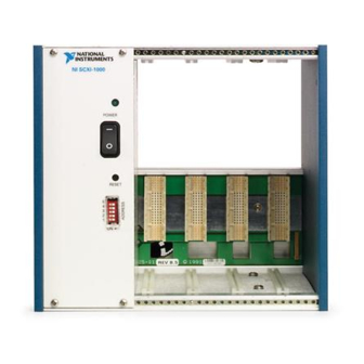
- Page 3 Confirm the correct power settings (100, 120, 220, or 240 VAC). Connect the power cord. ® 1 2 0 Front Chassis Power Switch Voltage Selection Tumbler Back Chassis Address Switch Power Cord Connector Figure 3. SCXI Chassis Setup © National Instruments Corporation SCXI Quick Start Guide...
- Page 4 PXI/SCXI Combination Chassis You must have a system controller installed in the PXI side of the chassis. Refer to ni.com/info type for more information on ordering a configured PXI/SCXI combination chassis through rdfis5 Factory Installation Services. Power off both the PXI and SCXI power switches, and unplug the chassis. Set the SCXI chassis address switch positions to the desired address.
- Page 5 Connect the USB cable from the computer port or from any other USB hub to the USB port on the SCXI USB module. Attach the cable to the strain relief using a cable tie. © National Instruments Corporation SCXI Quick Start Guide...
- Page 6 ® Personal Computer USB Cable USB Hub SCXI USB Device Figure 7. Installing an SCXI USB Module Add a Module to an Existing SCXI System You also can add a module to an existing SCXI system in multiplexed mode. If your system already has a controller established, you can simply install additional SCXI modules in any available chassis slots as previously described.
- Page 7 For information about sensors, refer to or Sensors in the NI-DAQmx Help, which ni.com/sensors you can access from Start»All Programs»National Instruments»NI-DAQ»NI-DAQmx Help. For information about IEEE 1451.4 TEDS smart sensors, refer to ni.com/teds Step 6. Attach the Terminal Blocks SCXI Chassis or PXI/SCXI Combination Chassis If you installed direct-connect modules, skip to Step 7.
- Page 8 50-pin connector. SCXI-1000 chassis through revision D do not have address jumpers or switches and respond to any address, but you cannot use them in multichassis systems. Revision E chassis use jumpers on Slot 0 for chassis addressing.
- Page 9 Repeat steps 1 through 3 for each SCXI chassis in the system, excluding the last SCXI chassis in the chain. SCXI-1000, SCXI-1001, or SCXI-1000DC Chassis SCXI-1346 Cable Adapter Shielded Cable Connecting to TO NEXT CHASSIS Shielded Cable Connecting to FROM DAQ BOARD OR PREVIOUS CHASSIS Figure 11.
-
Page 10: Windows Device Recognition
– – – – – – Shielded Cable Connected to SCXI-1349 Cable Adapter Shielded Cable to DAQ Device Sensors Shielded Cable Connected to SCXI-1346 Cable Adapter Terminal Blocks SCXI Chassis DAQ Device Figure 12. Completed SCXI System Step 9. Power On the SCXI Chassis If you are using an SCXI chassis, the chassis power switch is shown in Figure 3, SCXI Chassis Setup. - Page 11 Select Close to turn off the NI Device Monitor. If you turn off the utility and want to turn it back on, you must go to Start»Programs»National Instruments»NI-DAQ»NI Device Monitor. Step 10. Confirm That the Chassis and Modules Are Recognized Complete the following steps: Double-click the Measurement &...
- Page 12 Add the SCXI Chassis If you installed an SCXI USB module, such as the SCXI-1600, skip to Step 12. Configure the Chassis and Modules. The SCXI USB module and associated chassis appear automatically under Devices and Interfaces. To add the chassis, complete the following steps. Right-click Devices and Interfaces and select Create New.
- Page 13 14. Select the DAQ device connected to the SCXI module from the Which device connects to this module? list. © National Instruments Corporation SCXI Quick Start Guide...
- Page 14 15. Select a DAQ device from the Module Digitizer list. • In multiplexed mode, you can select a different module to be the module digitizer. If the module is operating in multiplexed mode, make sure Multiplexed digitization mode is selected. •...
-
Page 15: Step 13. Test The Chassis
Make sure the SCXI chassis is powered on. – Make sure all SCXI modules are properly installed in the chassis as previously described. – Make sure the USB cable between the SCXI-1600 and the computer is properly connected. © National Instruments Corporation SCXI Quick Start Guide... -
Page 16: Troubleshooting
• After checking the preceding items, retest the SCXI chassis. • If the SCXI-1600 is not detected, complete the following steps: Press <F5> to refresh MAX. Verify that the SCXI-1600 Ready LED is bright green. If the LED is not bright green, power off the chassis, wait five seconds, and power on the chassis. - Page 17 What is causing this problem? The SCXI chassis has backplane fuses, fused at 1.5 A on the SCXI-1000 chassis and at 4 A on the SCXI-1001 chassis. One or both of the fuses might be blown.
-
Page 18: Worldwide Technical Support
Technical Support Information document packaged with your device. National Instruments corporate headquarters is located at 11500 North Mopac Expressway, Austin, Texas, 78759-3504. National Instruments also has offices located around the world to help address your support needs. Specifications... -
Page 19: Electromagnetic Compatibility
Certification column. Environmental Management National Instruments is committed to designing and manufacturing products in an environmentally responsible manner. NI recognizes that eliminating certain hazardous substances from our products is beneficial not only to the environment but also to NI customers. - Page 20 National Instruments, NI, ni.com, and LabVIEW are trademarks of National Instruments Corporation. Refer to the Terms of Use section on ni.com/legal for more information about National Instruments trademarks. Other product and company names mentioned herein are trademarks or trade names of their respective companies.
- Page 21 Ce document explique comment installer et configurer des modules de conditionnement de signal SCXI dans les châssis SCXI-1000, SCXI-1001, SCXI-1000DC ou des châssis combinés PXI/SCXI, vérifier que le module et le châssis fonctionnent correctement et configurer des systèmes multichâssis. Il décrit également le logiciel NI-DAQmx en ce qui concerne les produits de conditionnement de signal SCXI...
- Page 22 Étape 2. Vérifiez les composants Vérifiez que vous disposez les composants du système SCXI, représentés dans les figures 1 et 2, nécessaires à votre application, ainsi que des éléments suivants : • Logiciel et documentation NI-DAQ 7.x ou version ultérieure •...
- Page 23 Vérifiez que les paramètres d’alimentation sont correctement définis (100, 120, 220 ou 240 V CA). Connectez le cordon d’alimentation. ® 1 2 0 Avant Interrupteur d’alimentation du châssis Sélecteur de tension Arrière Commutateur d’adresse du châssis Prise du cordon d’alimentation Figure 3. Configuration du châssis SCXI © National Instruments Corporation Guide de démarrage SCXI...
- Page 24 Châssis combiné PXI/SCXI Un contrôleur système doit être installé dans la partie PXI du châssis. Allez sur ni.com/frinfo tapez pour obtenir des informations complémentaires sur la manière de commander un châssis rdfis5 combiné PXI/SCXI configuré auprès des services d’installation en usine (Factory Installation Services). Mettez les interrupteurs d’alimentation PXI et SCXI hors tension et débranchez le châssis.
- Page 25 Reliez le câble USB du port de l’ordinateur ou de tout autre hub USB au port USB du module USB SCXI. Connectez le câble au détenteur à l’aide d’une attache de câble. © National Instruments Corporation Guide de démarrage SCXI...
- Page 26 ® Ordinateur Câble USB Hub USB Périphérique USB SCXI Figure 7. Installation d’un module USB SCXI Ajout d’un module à un système SCXI existant Vous avez aussi la possibilité d’ajouter un module à un système SCXI existant en mode multiplexé. Si un contrôleur est déjà...
- Page 27 à ni.com/sensors la rubrique Capteurs communs de l’Aide NI-DAQmx, accessible à partir de Démarrer»Tous les programmes»National Instruments»NI-DAQ»Aide NI-DAQmx. Pour obtenir des informations sur les capteurs intelligents TEDS IEEE 1451.4, consultez le site ni.com/zone Étape 6. Connectez les blocs de connexion Châssis SCXI ou châssis combiné...
- Page 28 à 50 broches situé à l’arrière du module se trouvant à droite du module directement connecté au SCXI-1346. Les châssis SCXI-1000 de révision D et des révisions antérieures ne possèdent aucun cavalier ou commutateurs d’adresse et répondent à n’importe quelle adresse, mais ils ne peuvent pas être utilisés dans des systèmes multichâssis.
- Page 29 Fixez l’adaptateur à l’arrière du châssis SCXI à l’aide des vis fournies avec le SCXI-1346. Répétez les étapes 1 à 3 pour chaque châssis SCXI du système, à l’exception du dernier châssis SCXI de la chaîne. Châssis SCXI-1000, SCXI-1001 ou SCXI-1000DC Adaptateur de câble SCXI-1346 Câble blindé se connectant à TO NEXT CHASSIS Câble blindé...
- Page 30 Connectez l’autre extrémité du câble au connecteur FROM DAQ BOARD OR PREVIOUS CHASSIS du SCXI-1346 qui se trouve dans le châssis portant le numéro d’ID n+1. Répétez les étapes 3 et 4 pour les autres châssis jusqu’à ce que vous ayez atteint le dernier châssis. Connectez le câble blindé...
- Page 31 • Sélectionnez Fermer pour arrêter le Moniteur de périphériques NI. Si vous voulez redémarrer l’utilitaire après l’avoir arrêté, allez à Démarrer»Tous les programmes»National Instruments» NI-DAQ»Moniteur de périphériques NI. Étape 10. Confirmez que le châssis et les modules ont été reconnus Suivez ces étapes :...
- Page 32 Si votre périphérique n’apparaît pas, appuyez sur <F5> pour rafraîchir l’affichage dans MAX. Si votre périphérique n’est toujours pas reconnu, reportez-vous à la page ni.com/support/ install Étape 11. Ajoutez le châssis Identification du contrôleur PXI Si vous utilisez un châssis combiné PXI/SCXI, effectuez les étapes suivantes afin d’identifier le contrôleur PXI intégré...
- Page 33 Cliquez dans le champ Identificateur de périphérique et entrez un ID alphanumérique unique pour changer le nom du module SCXI. MAX fournit un nom par défaut pour Identificateur de périphérique. Si vous utilisez un accessoire connecté au module, sélectionnez-le dans Accessoire. © National Instruments Corporation Guide de démarrage SCXI...
- Page 34 Sélectionnez l’option Détails. La fenêtre Détails s’ouvre. 10. Si vous configurez un module SCXI doté de paramètres définis par des cavaliers, entrez les paramètres sélectionnés au niveau matériel sur l’onglet Cavaliers. 11. Cliquez sur l’onglet Accessoire. Sélectionnez un accessoire de module compatible dans la liste déroulante Accessoire.
- Page 35 Testez le châssis, comme décrit à l’Étape 13. Testez le châssis. Étape 13. Testez le châssis Développez la catégorie Périphériques et interfaces»Périphériques NI-DAQmx. Cliquez avec le bouton droit sur le nom du châssis à tester. © National Instruments Corporation Guide de démarrage SCXI...
- Page 36 Sélectionnez Tester pour vérifier que MAX reconnaît le châssis. Un message fournit des explications si le châssis n’a pas été reconnu. Pour vérifier que l’installation de chaque module s’est déroulée sans problème, faites un clic droit sur le module que vous voulez tester et cliquez sur Panneaux de test. Lors du test du SCXI-1600, le système SCXI intégral est testé.
-
Page 37: Dépannage
SCXI au personnel du service de support technique de National Instruments. Astuces Avant de contacter National Instruments, essayez les suggestions de dépannage suivantes : • Vérifiez que le châssis SCXI est sous tension. Si vous utilisez un châssis combiné PXI/SCXI, assurez-vous que le châssis PXI est sous tension. -
Page 38: Questions Fréquemment Posées
Quelle peut être l'origine du problème ? Le fond de panier du châssis SCXI est équipé de fusibles capables de supporter 1,5 A pour le châssis SCXI-1000 et 4 A pour le châssis SCXI-1001. Il est possible qu’un des deux fusibles, ou les deux, soient grillés. -
Page 39: Spécifications
Signal Conditioning Technical Support Information fourni avec votre périphérique. Le siège social de National Instruments est situé à l’adresse suivante : 11500 North Mopac Expressway, Austin, Texas, 78759-3504, États-Unis. National Instruments compte aussi des filiales dans le monde entier pour répondre à... - Page 40 (For information about China RoHS compliance, go to ni.com/environment/rohs_china National Instruments, NI, ni.com et LabVIEW sont des marques de National Instruments Corporation. Pour plus d’informations concernant les marques de National Instruments, veuillez vous référer à la partie Terms of Use sur le site .
- Page 41 NI-DAQmx im Hinblick auf SCXI-Hardware zu beachten ist. Um den Anweisungen dieser Anleitung folgen zu können, muss eine funktionsfähige, konfigurierte Datenerfassungskarte (DAQ-Karte) instal- liert sein und Sie müssen bereits eine Entwicklungsumgebung von National Instruments einschließlich der benötigten Treiber installiert haben. Sollte das nicht der Fall sein, installieren und konfigurieren Sie bitte eine solche Karte anhand der Anleitung Erste Schritte mit NI-DAQ, die im Lieferpaket des Geräts,...
- Page 42 Schritt 2: Überprüfen der Komponenten auf Vollständigkeit Vergewissern Sie sich, dass Sie mit der in den Abbildungen 1 und 2 dargestellten Kombination aus SCXI-Geräten arbeiten. Darüber hinaus benötigen Sie Folgendes: • Eine Version des NI-DAQ-Treibers ab 7.x und die dazugehörige Dokumentation •...
- Page 43 Vergewissern Sie sich, dass die korrekte Spannung verwendet wird (100, 120, 220 oder 240 V~). Schließen Sie das Netzkabel an. ® 1 2 0 Vorderseite Chassis-Netzschalter Spannungsregler Rückseite Chassis-Adressschalter Netzkabelanschluss Abbildung 3. Aufbau eines SCXI-Chassis © National Instruments Corporation Erste Schritte mit SCXI...
- Page 44 PXI/SCXI-Kombinations-Chassis In den PXI-Steckplätzen des Chassis muss sich ein System-Controller befinden. Die Bestellung eines konfigurierten PXI/SCXI-Kombinations-Chassis bei unseren Factory Installation Services ist auf unse- rer Website beschrieben. Geben Sie dazu auf die Buchstabenkombination ein. ni.com/info rdgnif Schalten Sie sowohl den PXI- als auch den SCXI-Netzschalter auf OFF und ziehen Sie den Netz- stecker des Chassis.
- Page 45 Einstecken des Moduls in das Chassis wie folgt: Schließen Sie das Modul mit dem USB-Kabel an den Computer oder einen anderen damit verbun- denen Hub an. Befestigen Sie die Zugentlastungsvorrichtung mit einem Kabelbinder am Kabel. © National Instruments Corporation Erste Schritte mit SCXI...
- Page 46 ® oder Computer USB-Kabel USB-Hub SCXI-Modul mit USB-Anschluss Abbildung 7. Anschluss eines SCXI-Moduls mit USB-Anschluss Hinzufügen von Modulen zu einem SCXI-System Module können auch in SCXI-Systeme eingesteckt werden, die im Multiplexmodus betrieben werden. Sollte es in Ihrem System bereits einen Controller geben, stecken Sie alle weiteren Module einfach wie beschrieben in die verbleibenden Steckplätze.
- Page 47 Informationen zu Sensoren finden Sie auf der Website oder in der Hilfe für ni.com/sensors NI-DAQmx im Abschnitt Übliche Sensortypen des Buchs Grundlagen der Messtechnik. Zum Öffnen der Hilfe klicken Sie auf Start»Alle Programme»National Instruments»NI-DAQ»Hilfe für NI-DAQmx. TEDS-Sensoren (Sensoren nach IEEE 1451.4) sind auf beschrieben. ni.com/teds Schritt 6: Befestigen der Anschlussblöcke...
- Page 48 Adapter (von der Rückseite des Chassis betrachtet) kein Kabel angeschlossen werden. SCXI-Chassis des Typs SCXI-1000 bis zur Version D haben keine Adressjumper oder -schalter und können beliebig adressiert werden. Sie sind jedoch nicht in Systemen mit mehreren Chassis verwendbar.
- Page 49 Chassis. Wiederholen Sie die Schritte 1 bis 3 für jedes SCXI-Chassis in Ihrem Messaufbau mit Ausnahme des letzten. Chassis des Typs SCXI-1000, SCXI-1001 oder SCXI-1000DC Kabeladapter des Typs SCXI-1346 abgeschirmtes Kabel, das mit TO NEXT CHASSIS verbunden ist Kabel, das mit FROM DAQ BOARD OR PREVIOUS CHASSIS verbunden ist Abbildung 11.
- Page 50 Bei manchen Windows-Versionen öffnet sich beim Anschließen eines Geräts von National Instruments der Assistent für das Suchen neuer Hardware. Wählen Sie aus, ob eine Verbindung zu Windows Update hergestellt werden soll. Die Voreinstellung auf der folgenden Seite lautet: Software automatisch installieren (empfohlen).
- Page 51 Alle Gerätezuweisungen löschen hebt die unter Immer diese Aktion ausführen ausgewählte Option auf. • Schließen beendet den NI-Gerätemonitor. Mit Start»Alle Programme»National Instruments» NI-DAQ»NI-Gerätemonitor kann das Programm wieder gestartet werden. Schritt 10: Überprüfung der automatischen Erkennung des Chassis und der Module Gehen Sie nach folgenden Schritten vor: Klicken Sie zum Öffnen des MAX das Symbol Measurement &...
- Page 52 Schritt 11: Hinzufügen weiterer Chassis Festlegen des PXI-Controllers Bei PXI/SCXI-Kombinations-Chassis gehen Sie zur Angabe des PXI-Controllers des Chassis folgen- dermaßen vor: Klicken Sie die Kategorie PXI System mit der rechten Maustaste an und wählen Sie Identify as. Bei RT-Systemen erweitern Sie zunächst die Kategorie Netzwerkumgebung, klicken dann das System doppelt an und klicken anschließend mit der rechten Maustaste auf PXI System.
- Page 53 Um den Namen des SCXI-Moduls zu ändern, klicken Sie in das Feld Gerätekennung. Der Name muss alphanumerisch sein und darf nur einmal vergeben werden. Der MAX generiert für jedes Gerät einen Standardnamen. Zusätzliche Komponenten sind im Feld Zubehör auszuwählen. © National Instruments Corporation Erste Schritte mit SCXI...
- Page 54 Klicken Sie auf die Schaltfläche Details. Es öffnet sich ein Fenster mit weiteren Einstellungen. 10. Bei der Konfiguration von Modulen mit Steckbrücken klicken Sie auf Jumper und geben Sie die an der Hardware vorgenommenen Einstellungen ein. 11. Klicken Sie auf die Registerkarte Zubehör. Wählen Sie im Feld Zubehör das verwendete Modul- zubehör aus.
- Page 55 Klicken Sie mit der rechten Maustaste auf den Namen des zu testenden Chassis. Wählen Sie Test, um zu überprüfen, ob das Chassis im MAX erkannt wurde. Bei fehlgeschlagener Erkennung erhalten Sie eine Fehlermeldung. © National Instruments Corporation Erste Schritte mit SCXI...
- Page 56 Schritt 14: Messungen mit NI-DAQmx Dieser Schritt ist nur dann erforderlich, wenn Sie Ihre Karte mit NI-DAQ oder einer Entwicklungsum- gebung von National Instruments programmieren. Weitere Informationen erhalten Sie unter Messungen mit NI-DAQmx in der Anleitung Erste Schritte mit NI-DAQ.
-
Page 57: Fehlersuche
Das Chassis ist eingeschaltet und die Module sind für den Multiplexmodus konfiguriert. Dennoch kann ich an keinem der Kanäle die erwarteten Messwerte erfassen. Wie kommt dieser Fehler zustande? Bei SCXI-Chassis gibt es auf der Backplane des Gehäuses Sicherungen (bei SCXI-1000 1,5-A-Sicherungen und SCXI-1001 4-A-Sicherungen), die eventuell durchgebrannt sind. © National Instruments Corporation... - Page 58 Wenn eine der LEDs nicht leuchtet, ist mindestens eine Sicherung durchgebrannt. Beim SCXI-1000 sind die Sicherungen nur nach Entfernen des Lüfters zugänglich. Beim SCXI-1001 befinden sie sich auf der Rückseite hinter dem rechten Lüfter in der Nähe des Stromversorgungsmoduls.
-
Page 59: Technische Daten
Unterstützung bei Signalaufbereitungsgeräten sind im Dokument Technical Support Information in der Packungsbeilage der Geräte beschrieben. Bei Anfragen wenden Sie sich bitte an eine Niederlassung von National Instruments. Die Adresse der Hauptgeschäftsstelle von National Instruments in den USA lautet: 11500 North Mopac Expressway, Austin, Texas, 78759-3504. - Page 60 (For information about China RoHS compliance, go to ni.com/environment/rohs_china National Instruments, NI, ni.com und LabVIEW sind Marken der Firma National Instruments Corporation. Nähere Informationen zu den Marken von National Instruments finden Sie im Abschnitt Terms of Use unter . Sonstige hierin erwähnte Produkt- und Firmenbezeichnungen ni.com/legal...
Need help?
Do you have a question about the SCXI-1000 and is the answer not in the manual?
Questions and answers