Sign In
Upload
Manuals
Brands
National Instruments Manuals
Control Unit
SCXI-1120/D
National Instruments SCXI-1120/D Manuals
Manuals and User Guides for National Instruments SCXI-1120/D. We have
7
National Instruments SCXI-1120/D manuals available for free PDF download: Getting Started, User Manual, Quick Start Manual, Calibration Procedure
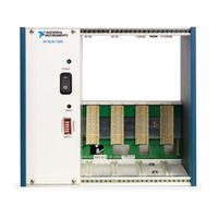
National Instruments SCXI-1120/D Getting Started (158 pages)
Brand:
National Instruments
| Category:
Control Unit
| Size: 1 MB
Table of Contents
Table of Contents
4
About this Manual
10
Conventions Used in this Guide
10
Related Documentation
12
Chapter 1 Introduction to SCXI
13
Appendix A
14
Appendix B
14
Figure 1-1. SCXI Systems
14
What You Need to Get Started
15
Identifying Your SCXI Components
15
Figure 1-2. SCXI System Components
16
SCXI Chassis
16
Figure 1-3. SCXI Chassis Signal Routing
17
SCXI Modules
17
Table 1-1. SCXI Modules
18
SCXI Terminal Blocks
19
Figure 1-4. Terminal Block Options
20
Table 1-2. Direct-Mount Terminal Blocks
21
Connector-And-Shell Assemblies
25
DAQ Modules
25
DAQ Plug-In Devices and PC Cards
25
SCXI Cable Assemblies
26
SCXI Multichassis System with Plug-In DAQ Device
26
Table 1-4. SCXI Cable Assemblies
26
Figure 1-5. Multichassis SCXI System with Shielded Cabling
27
Optional Software
27
Figure 1-6. the Relationship between the Programming Environment
28
Overview of SCXI Operation
29
Analog Input Modules
29
Figure 1-7. SCXI Signal Routing
30
Analog and Digital Output Modules
31
Chapter 2
32
Installing SCXI Modules and Connecting the SCXI System
32
To the DAQ Device
32
Installing Your Software
32
Installing Your DAQ Device
33
Installing Your SCXI Modules
33
Connecting the SCXI System to the DAQ Device or Computer
33
Using the Parallel Port
33
Using a Plug-In DAQ Device or Daqcard
33
Figure 2-1. Attaching the SCXI Cable Assembly to the SCXI Module and Chassis
35
Using an RS-232 or RS-485 Serial Port
37
Chapter 3 Configuring Your SCXI Hardware and Software
38
Module Configuration
38
Figure 3-1. Removing the SCXI Module Grounding Screw
38
Analog Modules
39
Figure 3-2. Removing the SCXI Module Cover
39
Ground-Referenced and Floating Signal Sources
40
SCXI-1100 Module
41
Table 3-1. SCXI-1100 Input Signal Referencing Jumper Configurations
42
Table 3-2. SCXI-1100 Filtering Jumper Configuration
43
SCXI-1102/B/C Module
44
Table 3-3. SCXI-1100 PGIA Output Referencing Jumper Configuration
44
SCXI-1104/C Module
45
SCXI-1112 Module
45
SCXI-1120/D Module
45
Table 3-4. Gain Jumper Allocation
46
Table 3-5. Gain Jumper Positions
47
Table 3-6. SCXI-1120 Filter Jumper Allocation
48
Table 3-7. SCXI-1120D Filter Jumper Allocation
49
SCXI-1121 Module
51
Table 3-8. SCXI-1120/D Signal Referencing Jumper Configuration
51
Table 3-10. SCXI-1121 Gain Jumper Configuration
53
Table 3-9. SCXI-1121 First-Stage and Second-Stage Gain
53
Table 3-11. SCXI-1121 First-Stage and Second-Stage Filter
54
Table 3-12. SCXI-1121 Excitation Mode Jumper Configuration
55
Table 3-13. SCXI-1121 Excitation Level Jumper Configuration
57
Table 3-14. SCXI-1121 Maximum Load Per Excitation Channel
58
Table 3-15. SCXI-1121 Half-Bridge Completion Network Jumper Configuration
59
SCXI-1122 Module
60
Current-Loop Receivers
62
Scanning Techniques
62
Figure 3-3. Scanning Techniques
63
SCXI-1124 Module
63
SCXI-1125 Module
65
SCXI-1126 Module
66
SCXI-1140 Module
66
DAQ Device Connections in Multiple-Module Systems
66
User-Configurable Jumpers and DIP Switches
66
SCXI-1141, SCXI-1142, and SCXI-1143 Modules
69
SCXI-1520 Module
71
SCXI-1530/1531 Module
72
SCXI-1540 Module
73
Digital SCXI Modules
73
Communication Modes
74
Parallel Mode
74
Serial Mode
74
SCXI-1160 Module
75
SCXI-1161 Module
75
SCXI-1162 Module
76
SCXI-1162HV Module
79
SCXI-1163 Module
81
SCXI-1163R Module
84
SCXI-1200 Module
87
Parallel Port Interface
87
Analog I/O Configuration
88
Module Configuration
88
Analog Input Configuration
89
Analog Output Configuration
89
Analog Input Polarity and Range Configuration
91
Figure 3-4. SCXI-1200 Front Connector Pin Assignments
92
SCXI-1180 Feedthrough Panel
93
SCXI-1181 Breadboard Module
93
SCXI-2400 Serial Communications Module
93
Baud Rate and Address Configuration
94
Figure 3-5. SCXI-2400 Module Default Switch Settings
94
SCXI Chassis
95
Baud Rate and Address Configuration
95
SCXI-1000, SCXI-1000DC, and SCXI-1001 Chassis
95
SCXI-2000 Chassis with Serial Communications
95
Configure Your Software for Use with SCXI Products
96
Example Programs
96
Chapter 4 Connecting and Using Accessories and Transducers
97
Connecting Signal Wires to the SCXI System
97
SCXI-13XX Terminal Blocks
100
TBX Terminal Blocks
100
Figure 4-1. TBX Terminal Block Cabled to an SCXI Module
100
Onboard Temperature Sensors for Cold-Junction Compensation
101
Opening the SCXI-13XX Terminal Block
102
Figure 4-2. Removing the Terminal Block Grounding Screw
102
Figure 4-3. Removing the Terminal Block Cover
102
Connector-And-Shell Assemblies
103
Connecting Transducers to the SCXI System
103
Thermocouples
103
Using Thermocouples with the SCXI-1100
103
Using Thermocouples with the SCXI-1102
104
Using Thermocouples with the SCXI-1112, SCXI-1120, SCXI-1121, SCXI-1122, and SCXI-1125
104
Noise and Filtering
105
Strain Gauges
105
Figure 4-4. Connecting the Half-Bridge Strain Gauge to Channel 1 of the
106
Figure 4-5. Quarter-Bridge Configurations
108
Figure 4-6. Half-Bridge Configurations
109
Figure 4-7. Full-Bridge Configurations
110
Figure 4-8. SCXI-1520 to SCXI-1314 Quarter-Bridge Connection
112
Figure 4-9. SCXI-1520 to SCXI-1314 Half-Bridge Connection
113
Figure 4-10. SCXI-1520 to SCXI-1314 Full-Bridge Connection
114
Rtds
115
Current Excitation
117
Analog Circuitry in the SCXI-1122
119
Analog Input Channels
120
Excitation Output Channels
121
Analog Output Channel Signal Connections on the SCXI-1124
124
Chassis Ground Connections
127
Lvdts, Rvdts, and Resolvers
127
Connecting to Lvdts and Rvdts
128
Synchronizing Channels
129
Connecting to Resolvers
131
Advertisement
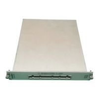
National Instruments SCXI-1120/D User Manual (75 pages)
Eight-Channel Isolated Analog Input Module and Eight-Channel Wide Band Isolated Analog Input Module for Signal Conditioning
Brand:
National Instruments
| Category:
I/O Systems
| Size: 3 MB
Table of Contents
Table of Contents
5
About this Manual
8
Conventions
8
National Instruments Documentation
9
About the SCXI-1120/D
10
Introduction
10
What You Need to Get Started
11
National Instruments Application Software
12
Software Programming Choices
12
Unpacking
12
NI-DAQ Driver Software
13
Figure 1-1. the Relationship between the Programming Environment
14
Optional Equipment
14
Configuration and Installation
15
Module Configuration
15
Figure 2-1. SCXI-1120/D Parts Locator Diagram
16
Digital Signal Connections
18
Figure 2-2. Removing the SCXI Module Cover
18
Using Jumpers W42 and W43
19
Using Jumper W44 on Revision C of the SCXI-1120 and All Revisions of the SCXI-1120D
20
Using Jumper W44 on Revisions a and B of the SCXI-1120
20
Table 2-1. Digital Signal Connections, Jumper Settings
21
Analog Configuration
22
Grounding, Shielding, and Reference-Mode Selection
22
Table 2-2. Jumper W46 Settings
23
Direct Temperature Connection
24
Gain Jumpers for the SCXI-1120/D
24
Table 2-3. Jumper W41 Settings
24
Table 2-4. Gain Jumper Allocation
24
Table 2-5. Gain Jumper Positions
25
SCXI-1120 Filter Jumpers
26
Table 2-6. SCXI-1120 Filter Jumper Allocation
26
SCXI-1120D Filter Jumpers
27
Table 2-7. SCXI-1120D Filter Jumper Allocation
27
Hardware Installation
28
Signal Connections
29
Figure 3-1. SCXI-1120/D Front Connector Pin Assignments
31
SCXI-1120/D Front Connector
31
Front Connector Signal Descriptions
32
Table 3-1. SCXI-1120/D Front Connector Signal Descriptions
32
Analog Input Channels
33
Figure 3-2. Ground-Referenced Signal Connection for the SCXI-1120/D with High Common-Mode Voltage
33
Figure 3-3. Floating Signal Connection for the SCXI-1120/D Referenced to
33
Floating AC-Coupled Signal Connection for the SCXI-1120
34
High Common-Mode Voltage
34
Floating AC-Coupled Signal Connection for the SCXI-1120D
35
High Common Mode Voltage
35
Temperature Sensor Connection
35
SCXI-1120/D Rear Connector
36
SCXI-1120/D Rear Signal Connector Pin Assignments
36
Rear Connector Signal Descriptions
37
Table 3-2. Rear Connector Signal Descriptions
37
Analog Output Signal Connections
38
Table 3-3. Scxibus to SCXI-1120/D Rear Connector to DAQ Device Pin Equivalencies
39
Functional Overview
40
Theory of Operation
40
Power-Up State
41
Digital Interface Circuitry Block Diagram
42
Scxibus Connector and Digital Interface
42
Digital Control Circuitry
43
Analog and Timing Circuitry
44
Analog Input Block Diagram
45
Analog Input Channels
45
Analog Output Circuitry
48
Calibration
51
Calibration Equipment Requirements
51
Offset Null Adjust
51
Table 5-1. Calibration Potentiometers Reference Designators
52
Appendix A Specifications
53
Table A-1. Input Signal Range
57
Table A-2. System Noise RTI (0.1 Hz to 50 Khz
58
Table A-3. Switching Supply Noise (Approximately at 100 Khz
59
Technical Support Resources
61
Glossary
63
Index
70
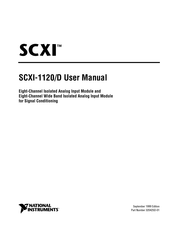
National Instruments SCXI-1120/D User Manual (73 pages)
Eight-Channel Isolated Analog Input Module and Eight-Channel Wide Band Isolated Analog Input Module for Signal Conditioning
Brand:
National Instruments
| Category:
I/O Systems
| Size: 0 MB
Table of Contents
Table of Contents
4
About this Manual
7
Conventions
7
National Instruments Documentation
8
About the SCXI-1120/D
9
Introduction
9
What You Need to Get Started
10
National Instruments Application Software
11
Software Programming Choices
11
Unpacking
11
NI-DAQ Driver Software
12
Figure 1-1. the Relationship between the Programming Environment
13
Optional Equipment
13
Configuration and Installation
14
Module Configuration
14
Figure 2-1. SCXI-1120/D Parts Locator Diagram
15
Digital Signal Connections
17
Figure 2-2. Removing the SCXI Module Cover
17
Using Jumpers W42 and W43
18
Using Jumper W44 on Revision C of the SCXI-1120 and All Revisions of the SCXI-1120D
19
Using Jumper W44 on Revisions a and B of the SCXI-1120
19
Table 2-1. Digital Signal Connections, Jumper Settings
20
Analog Configuration
21
Grounding, Shielding, and Reference-Mode Selection
21
Table 2-2. Jumper W46 Settings
22
Direct Temperature Connection
23
Gain Jumpers for the SCXI-1120/D
23
Table 2-3. Jumper W41 Settings
23
Table 2-4. Gain Jumper Allocation
23
Table 2-5. Gain Jumper Positions
24
SCXI-1120 Filter Jumpers
25
Table 2-6. SCXI-1120 Filter Jumper Allocation
25
SCXI-1120D Filter Jumpers
26
Table 2-7. SCXI-1120D Filter Jumper Allocation
26
Hardware Installation
27
Signal Connections
28
Figure 3-1. SCXI-1120/D Front Connector Pin Assignments
30
SCXI-1120/D Front Connector
30
Front Connector Signal Descriptions
31
Table 3-1. SCXI-1120/D Front Connector Signal Descriptions
31
Analog Input Channels
32
Figure 3-2. Ground-Referenced Signal Connection for the SCXI-1120/D with High Common-Mode Voltage
32
Figure 3-3. Floating Signal Connection for the SCXI-1120/D Referenced to
32
Floating AC-Coupled Signal Connection for the SCXI-1120
33
High Common-Mode Voltage
33
Floating AC-Coupled Signal Connection for the SCXI-1120D
34
High Common Mode Voltage
34
Temperature Sensor Connection
34
SCXI-1120/D Rear Connector
35
SCXI-1120/D Rear Signal Connector Pin Assignments
35
Rear Connector Signal Descriptions
36
Table 3-2. Rear Connector Signal Descriptions
36
Analog Output Signal Connections
37
Table 3-3. Scxibus to SCXI-1120/D Rear Connector to DAQ Device Pin Equivalencies
38
Functional Overview
39
Theory of Operation
39
Power-Up State
40
Digital Interface Circuitry Block Diagram
41
Scxibus Connector and Digital Interface
41
Digital Control Circuitry
42
Analog and Timing Circuitry
43
Analog Input Block Diagram
44
Analog Input Channels
44
Analog Output Circuitry
47
Calibration
50
Calibration Equipment Requirements
50
Offset Null Adjust
50
Table 5-1. Calibration Potentiometers Reference Designators
51
Appendix A Specifications
52
Table A-1. Input Signal Range
56
Table A-2. System Noise RTI (0.1 Hz to 50 Khz
57
Table A-3. Switching Supply Noise (Approximately at 100 Khz
58
Technical Support Resources
60
Glossary
62
Index
69
Advertisement
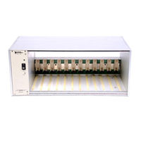
National Instruments SCXI-1120/D Quick Start Manual (61 pages)
Signal Conditioning eXtensions for Instrumentation
Brand:
National Instruments
| Category:
Control Unit
| Size: 4 MB
Table of Contents
PXI/SCXI Combination Chassis
3
Step 4. Install the Modules
4
SCXI USB Modules
5
Single-Chassis System
7
Multichassis System
8
Windows Device Recognition
10
Identify the PXI Controller
11
Use Your Task in an Application
15
Troubleshooting
16
Frequently Asked Questions
16
Worldwide Technical Support
18
Specifications
18
Environmental Management
19
Waste Electrical and Electronic Equipment (WEEE)
19
Dépannage
35
Questions Fréquemment Posées
36
Spécifications
38
Compatibilité Électromagnétique
38
SCXI-Chassis
42
Fehlersuche
56
Häufig Gestellte Fragen
57
Elektromagnetische Verträglichkeit
59
National Instruments SCXI-1120/D User Manual (16 pages)
Brand:
National Instruments
| Category:
Computer Hardware
| Size: 0 MB
Table of Contents
Table of Contents
1
Introduction
2
What Is Calibration
2
Why Should You Calibrate
2
How Often Should You Calibrate
2
Equipment and Other Test Requirements
3
Test Equipment
3
Connectors
3
Documentation
4
Software
4
Test Conditions
5
Calibration Procedures
5
Configuring Your Module for Calibration
5
Configuring Digital Jumpers
7
Configuring Gain Jumpers
8
Configuring SCXI-1120 Filter Jumpers
9
Configuring SCXI-1120D Filter Jumpers
10
Configuring Potentiometers
12
Setting up Your Module for Calibration
12
Connecting Your Calibrator, DMM, and SCXI Module
13
Running the Calibration Procedure
14
Technical Support Resources
16
NI Web Support
16
Worldwide Support
16
National Instruments SCXI-1120/D Quick Start Manual (25 pages)
Signal Conditioning eXtensions for Instrumentation
Brand:
National Instruments
| Category:
Test Equipment
| Size: 2 MB
Table of Contents
Step 4. Install the Modules
6
Windows Device Recognition
12
Troubleshooting
19
Frequently Asked Questions
20
Worldwide Technical Support
21
Specifications
22
Electromagnetic Compatibility
22
Online Product Certification
22
Environmental Management
23
National Instruments SCXI-1120/D Calibration Procedure (19 pages)
Brand:
National Instruments
| Category:
Control Unit
| Size: 0 MB
Table of Contents
Test Equipment
2
Software and Documentation
2
Test Conditions
3
Setting up the Module
4
Specifications
15
Advertisement
Related Products
National Instruments SCXI-1126
National Instruments SCXI-1124
National Instruments SCXI SCXI-1102
National Instruments SCXI SCXI-1102B
National Instruments SCXI-116 Series
National Instruments SCXI-1112
National Instruments SCXI-1102/B/C
National Instruments SCXI-1162
National Instruments SCXI-1163R
National Instruments SCXI-1181
National Instruments Categories
Control Unit
I/O Systems
Controller
Computer Hardware
Measuring Instruments
More National Instruments Manuals
Login
Sign In
OR
Sign in with Facebook
Sign in with Google
Upload manual
Upload from disk
Upload from URL