Renesas R-IN32M3 Quick Start Manual
Industrial ethernet module solution
Hide thumbs
Also See for R-IN32M3:
- User manual (244 pages) ,
- Quick start manual (25 pages) ,
- User manual (122 pages)
Table of Contents
Advertisement
Quick Links
R-IN32M3 Module (RY9012A0)
Industrial Ethernet Module Solution
1. Introduction
This document describes the integration of R-IN32M3 Module on the Renesas Synergy™ platform with the
e2studio development environment. Synergy S7G2 microcontroller on the Synergy board is used as the
application controller and communicates with the embedded MCU of R-IN32M3 Module. The module takes
care for the complex handling of the Industrial Ethernet protocols (like PROFINET
control of the application processor. The example SW is provided in source code and thus can be ported to
other development platforms and target MCUs. Thus, it is possible with this R-IN32M3 Module Starter Kit to
quickly develop a prototype for a target application for the Industrial Ethernet market.
The software package which is available with R-IN32M3 Module Starter Kit is not only the integrated
software development environment and example software but includes a Management Tool (of company
"port GmbH") which can be used for protocol monitoring and control system. R-IN32M3 Module Starter Kit
prototype application and its communication module can be configured and monitored. Even an update of R-
IN32M3 Module's firmware is possible via Ethernet.
®
With its ARM
core based S7G2 controller the starter kit enables the user
⎯ to quickly familiarize with the Industrial Ethernet protocols (like PROFINET or EtherNet/IP) by use of
an application example
⎯ to quickly develop an application on the industry-standard ARM microcontroller of the Renesas
Synergy SK-S7G2 Starter Kit
⎯ to have a protocol monitoring and control system
2.
Hardware of R-IN32M3 Module Starter Kit
2.1 Preparations System Requirements
To work with Renesas Synergy SK-S7G2 Starter Kit Rev.3.3 or higher, a PC with the following features
is required:
⎯ Microsoft
®
Windows
•
≥ 8 GB system RAM
•
≥ 2 GB free hard drive space
•
≥ 2 USB 2.0 ports
⎯ Internet connection
2.2 Hardware configuration
2.2.1 Configuration of R-IN32M3 Module board
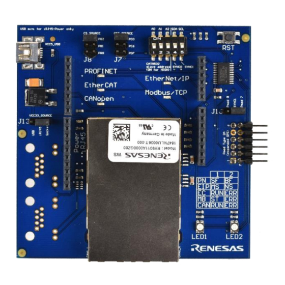
Renesas provides a hardware board for evaluation which contains R-IN32M3 Module with two Ethernet
connectors and an integrated Ethernet switch. On-board connectors according to industry standards can be
operated in Arduino™ compatible mode and in Pmod™ mode.
R12QS0038EE0100 2
Jan.27.2020
Core family processor or equivalent running at ≥ 2.0 GHz
®
®
with Intel
Quick Start Guide
®
or EtherNet/IP
®
) under
Advertisement
Table of Contents

Related Manuals for Renesas R-IN32M3


Summary of Contents for Renesas R-IN32M3
- Page 1 The example SW is provided in source code and thus can be ported to other development platforms and target MCUs. Thus, it is possible with this R-IN32M3 Module Starter Kit to quickly develop a prototype for a target application for the Industrial Ethernet market.
- Page 2 The Synergy board has two Pmod ports. In case of using Pmod mode, connect jumpers J15 and J13 on the Synergy board to supply 3.3V power supply on the Pmod channel of choice to R-IN32M3 Module. Before connecting the Synergy board with R-IN32M3 Module board is recommended first to get the Synergy board up and running.
-
Page 3: Management Tool
The e2-studio is an Integrated Software Development Environment (ISDE). The ISDE is available on the webpage of Renesas as seen in the Quick Start Guide of the MCU board. A free Synergy license is required to use the SSP. The evaluation license is included with SSP installer, that can be downloaded after creating a Synergy account. - Page 4 R-IN32M3 Module Quick Start Guide “Allowed apps” window open, click “Change settings” and then click “Allow another app..”. Figure 3: Allowed applications Click “Browse..” and select the “mantool.exe” from Management tool folder. Then, click “Network types…” and set enabled all network type (“Domain”, “Private” and “Public”) and click “OK” and “Add”.
- Page 5 R-IN32M3 Module Quick Start Guide “mantool.exe” show on allowed apps list. Then, click “OK”. Figure 5: Allowed Management Tool R12QS0038EE0100 Page 1-5 Jan.27.2020...
-
Page 6: Project Import
2.3.6 Wireshark The Management Tool also offers a function to create a log file of all relevant parameters of R-IN32M3 Module. For a more detailed protocol analysis it is recommended to install the Wireshark tools. The Wireshark tools is freeware and can be downloaded at https://www.wireshark.org. - Page 7 R-IN32M3 Module Quick Start Guide Figure 7: e2-studio import project dialog 3.3 License Register License registration is required to use SSP. If e2-studio requests a license, register a license. The evaluation license is included with SSP installer, that can be downloaded after creating a Synergy account.
-
Page 8: Project Configuration
After the Build is finished without errors and warnings, the compilation was successful. The resulting binary can be started now. Be sure that the Renesas Synergy board is connected to the workstation via USB. Then select the “Debug As“ option from the drop down menu and choose item “3 Renesas GDB Hardware Debugging”... - Page 9 R-IN32M3 Module Quick Start Guide Figure 11: Initiate debug session R12QS0038EE0100 Page 1-9 Jan.27.2020...
- Page 10 R-IN32M3 Module Quick Start Guide In the next step you will be prompted to select a debugging hardware. Choose „J-Link ARM“ for the Renesas Synergy SK-S7G2 board. After selecting the Debug mode, it is necessary to select chip model (R7F5G26H).
-
Page 11: Device Detection
4.1 Device Detection At first a communication needs to be established with R-IN32M3 Module. Thus, connect R-IN32M3 Module to the Ethernet network connector of the PC. Between the management PC and R-IN32M3 Module a R12QS0038EE0100 Page 1-11... - Page 12 The following dialog appears and 1 found device will be reported: Figure 17: Scan Network dialog As a result, R-IN32M3 Module will be shown as a new device in the „Network Navigator“ within the scanned network. R12QS0038EE0100 Page 1-12...
- Page 13 Please select the newly found R-IN32M3 module for further steps. 4.2 Config Manager / IP Configuration This panel provides access to the config manager variables of R-IN32M3 Module (volatile and non-volatile stored configuration variables). To read a list of all variables, select the “Read configuration” button.
- Page 14 Figure 20: Management Tool Configuration Manager To communicate with R-IN32M3 Module, the IP address of R-IN32M3 Module must be within the same IP network as the IP address of the Management PC IP address. Thus, chose a valid IP address and configure R-IN32M3 Module accordingly.
- Page 15 When prompted if changed values shall be written, answer “Yes”. Afterwards the locally modified values are transferred to R-IN32M3 Module, where there are only modified in RAM. To make permanent changes, use the “Save config to flash” button. Modified IP settings are applied after restart of the system (a power off / power on cycle the Renesas Synergy board and R-IN32M3 Module).
- Page 16 Quick Start Guide 4.3 Updating the R-IN32M3 Module Firmware Under control of the management tool the firmware of the embedded communication controller of R-IN32M3 Module can be updated. The firmware file will be sent via the Ethernet connection. Figure 23: R-IN32M3 Module firmware update...
- Page 17 Figure 24: Management PROFINET master Use the “Wink” command to identify the connected R-IN32M3 Module, which will be shown with a flashing “LED1” on R-IN32M3 Module board. To establish a cyclic PROFINET communication use the I/O panel of the PNIO Master.
- Page 18 Please start the example “06_eip_io_data_static” according to the previous description. To establish an EtherNet/IP communication, at first R-IN32M3 Module must be selected in the “Network Navigator”. Then select the “EtherNet/IP Master” function panel. At first use “Scan device” to detect the EtherNet/IP device.
- Page 19 The example application on the application controller will mirror the output data to the input data. I/O data can be manipulated and monitored in the I/O Data tables. Beside that if a connection is established, the “LED1” and “LED2” Leds on R-IN32M3 Module board will both be green. R12QS0038EE0100 Page 1-19 Jan.27.2020...
-
Page 20: General Precautions In The Handling Of Microprocessing Unit And Microcontroller Unit Products
Unit Products The following usage notes are applicable to all Microprocessing unit and Microcontroller unit products from Renesas. For deta iled usage notes on the products covered by this document, refer to the relevant sections of the document as well as any technical updates that have been issued for the products. -
Page 21: Corporate Headquarters
You are responsible for implementing safety measures to gua rd against the possibility of bodily injury, injury or damage caused by fire, and/or danger to the public in the event of a failure or malfunction of Renesas Elec tronics products, such as safety design for hardware and software, including but not limited to redundancy, fire control and malfunction prevention, appropriate treatment for aging degradation or any other appropriate measures.
Need help?
Do you have a question about the R-IN32M3 and is the answer not in the manual?
Questions and answers