Advertisement
Quick Links
INVERTER
A800-E
FR-A862-E (SEPARATED CONVERTER TYPE)
INSTRUCTION MANUAL (HARDWARE)
High functionality and high performance
FR-A862-05450 to 08500-E
INTRODUCTION
INSTALLATION AND WIRING
PRECAUTIONS FOR USE OF
THE INVERTER
PROTECTIVE FUNCTIONS
PRECAUTIONS FOR
MAINTENANCE AND
INSPECTION
SPECIFICATIONS
1
2
3
4
5
6
Advertisement

Related Manuals for Mitsubishi Electric FR-A862-05450-E


Summary of Contents for Mitsubishi Electric FR-A862-05450-E
- Page 1 INVERTER A800-E FR-A862-E (SEPARATED CONVERTER TYPE) INSTRUCTION MANUAL (HARDWARE) High functionality and high performance FR-A862-05450 to 08500-E INTRODUCTION INSTALLATION AND WIRING PRECAUTIONS FOR USE OF THE INVERTER PROTECTIVE FUNCTIONS PRECAUTIONS FOR MAINTENANCE AND INSPECTION SPECIFICATIONS...
- Page 2 Instruction Manual. If a product is used without any • A person who took a proper engineering training. Such training may be available at your local Mitsubishi Electric inspection, a burst, breakage, or a fire may occur. office. Contact your local sales office for schedules and ...
- Page 3 Caution Caution Transportation and Mounting Usage The storage temperature (applicable for a short time, e.g. during The electronic thermal relay function does not guarantee transit) must be between -20 and +65°C. Otherwise the inverter protection of the motor from overheating. It is recommended to may be damaged.
- Page 4 CONTENTS 1 INTRODUCTION Product checking and accessories Inverter component names About the related manuals 2 INSTALLATION AND WIRING Peripheral devices 2.1.1 Inverter and peripheral devices ........................12 2.1.2 Peripheral devices ............................14 Removal and reinstallation of the front cover Installation of the inverter and enclosure design 2.3.1 Inverter installation environment........................17 2.3.2...
- Page 5 Electro-magnetic interference (EMI) and leakage currents 3.1.1 Leakage currents and countermeasures......................54 3.1.2 Countermeasures against inverter-generated EMI ..................55 Power supply harmonics 3.2.1 Power supply harmonics ..........................57 Installation of a reactor Power-OFF and magnetic contactor (MC) Countermeasures against deterioration of the 600 V class motor insulation Checklist before starting operation Failsafe system which uses the inverter 4 PROTECTIVE FUNCTIONS...
- Page 6 Inverter rating Common specifications Outline dimension drawings 6.3.1 Inverter outline dimension drawings .......................85 APPENDIX Appendix 1 For customers replacing the conventional model with this inverter........88 Appendix 2 Comparison with FR-A860...................... 90 Appendix 3 Instructions for UL and cUL ....................91 Appendix 4 Restricted Use of Hazardous Substances in Electronic and Electrical Products .....
- Page 7 MEMO...
- Page 8 INTRODUCTION This chapter contains the descriptions that must be read before using this product. Always read the instructions before using the equipment. 1.1 Product checking and accessories.........8 1.2 Inverter component names ............9 <Abbreviations> DU ..........Operation panel (FR-DU08) Operation panel ......Operation panel (FR-DU08) and LCD operation panel (FR-LU08) Parameter unit .......
- Page 9 Product checking and accessories Product checking and accessories Unpack the product and check the rating plate and the capacity plate of the inverter to ensure that the model agrees with the order and the product is intact. Applicable inverter model Communication Symbol Voltage class Symbol Structure, functionality...
- Page 10 Inverter component names Inverter component names Component names are shown below. Refer to Symbol Name Description page Plug-in option connector 1 Instruction Connects a plug-in option or a communication option. Manual of Plug-in option connector 3 the option The connector 2 cannot be used because the Ethernet board is installed in the initial status.
- Page 11 About the related manuals About the related manuals The manuals related to FR-A862-E are shown below. Manual name Manual number FR-A860 Instruction Manual (Detailed) IB-0600563ENG FR-A800-E Ethernet Function Manual IB-0600628ENG FR-CC2 (Converter unit) Instruction Manual IB-0600572ENG FR Configurator 2 Instruction Manual IB-0600516ENG FR-A800/F800 PLC Function Programming Manual IB-0600492ENG...
- Page 12 INSTALLATION AND WIRING This chapter explains the "installation" and the "wiring" of this product. Always read the instructions before using the equipment. 2.1 Peripheral devices ..............12 2.2 Removal and reinstallation of the front cover......15 2.3 Installation of the inverter and enclosure design ....17 2.4 Terminal connection diagrams ..........24...
- Page 13 Peripheral devices Peripheral devices 2.1.1 Inverter and peripheral devices (c) Three-phase AC power supply (d) Molded case (b) Converter unit (a) Inverter (h) USB connector circuit breaker (FR-CC2) (FR-A862) USB host (MCCB) or earth (A connector) leakage current breaker (ELB), Communication fuse status indicator...
- Page 14 Peripheral devices Refer Symbol Name Overview page The life of the inverter and the converter unit is influenced by the surrounding air temperature. Inverter (FR-A862) The surrounding air temperature should be as low as possible within the permissible range. This must be noted especially when the inverter is installed in an enclosure.
- Page 15 Peripheral devices 2.1.2 Peripheral devices Selecting the converter unit (FR-CC2) Select the capacity of the FR-CC2 converter unit according to the connected motor capacity. Inverter Converter unit Model Rated current Motor capacity FR-CC2-[ ] FR-A862-[ ] (kW) C355K 05450 C400K 06470 C560K...
- Page 16 Removal and reinstallation of the front cover Removal and reinstallation of the front cover Removal of the front cover (lower side) Remove the mounting screws to remove the front cover (lower side). (The number of the mounting screws differs by the capacity.) With the front cover (lower side) removed, wiring of the main circuit terminals can be performed.
- Page 17 Removal and reinstallation of the front cover Reinstallation of the front covers Fasten Fasten Fasten Fasten Fasten Fasten Insert the upper hooks of the front cover (upper side) into the sockets of the inverter. Securely install the front cover (upper side) to the inverter by fixing the hooks on the sides of the cover into place. Tighten the mounting screw at the lower part of the front cover (upper side).
- Page 18 Installation of the inverter and enclosure design Installation of the inverter and enclosure design When designing or manufacturing an inverter enclosure, determine the structure, size, and device layout of the enclosure by fully considering the conditions such as heat generation of the contained devices and the operating environment. An inverter uses many semiconductor devices.
- Page 19 Installation of the inverter and enclosure design Humidity Operate the inverter within the ambient air humidity of usually 45 to 95%. Too high humidity will pose problems of reduced insulation and metal corrosion. On the other hand, too low humidity may cause a spatial electrical breakdown. The insulation distance defined in JEM1103 "Control Equipment Insulator"...
- Page 20 Installation of the inverter and enclosure design Vibration, impact The vibration resistance of the inverter is up to 2.9 m/s at 10 to 55 Hz frequency and 1 mm amplitude for the directions of X, Y, Z axes. Applying vibration and impacts for a long time may loosen the structures and cause poor contacts of connectors, even if those vibration and impacts are within the specified values.
- Page 21 Installation of the inverter and enclosure design 2.3.3 Inverter installation Inverter placement • Install the inverter on a strong surface securely with screws. • Leave enough clearances and take cooling measures. • Avoid places where the inverter is subjected to direct sunlight, high temperature and high humidity. •...
- Page 22 Installation of the inverter and enclosure design Encasing multiple inverters and converter units When multiple inverters and converter units are placed in the same enclosure, generally arrange them horizontally as shown in the figure on the right. Converter Converter Inverter Inverter unit unit...
- Page 23 Installation of the inverter and enclosure design 2.3.4 Protruding the heatsink When encasing an inverter to an enclosure, the heat generated in the enclosure can be greatly reduced by protruding the heatsink of the inverter. When installing the inverter in a compact enclosure, etc., this installation method is recommended. ...
- Page 24 Installation of the inverter and enclosure design Removal of the rear installation frame Two installation frames are attached to each of the upper and lower parts of the inverter. Remove the rear side installation frame on the top Upper installation and bottom of the inverter as shown on the right.
- Page 25 Terminal connection diagrams Terminal connection diagrams Sink logic Main circuit terminal Control circuit terminal Converter unit R/L1 Motor S/L2 T/L3 Jumper Earth (Ground) R1/L11 S1/L21 Earth Main circuit (Ground) Control circuit Control input signals Relay output (No voltage input allowed) Forward rotation start Relay output 1 Reverse rotation start...
- Page 26 Terminal connection diagrams Terminals R1/L11 and S1/L21 are connected to terminals P/+ and N/- with a jumper respectively. When using separate power supply for the control circuit, remove the jumpers from R1/L11 and S1/L21. The function of these terminals can be changed with the input terminal assignment (Pr.178 to Pr.189). ...
- Page 27 Main circuit terminals Main circuit terminals 2.5.1 Details on the main circuit terminals of the inverter Terminal Refer Terminal name Terminal function description symbol to page Connect these terminals to a three-phase squirrel cage motor or an PM U, V, W Inverter output motor.
- Page 28 Main circuit terminals 2.5.3 Terminal layout of the main circuit terminals, wiring of power supply and the motor FR-CC2-C355K to FR-CC2-C560K FR-A862-05450 to FR-A862-08500 R1/L11 S1/L21 Charge lamp R1/L11 S1/L21 Charge lamp Jumper Jumper R/L1 T/L3 S/L2 To converter To inverter unit Power supply Motor...
- Page 29 Main circuit terminals 2.5.4 Applicable cables and wiring length Select a recommended cable size to ensure that the voltage drop will be 2% or less. If the wiring distance is long between the inverter and motor, the voltage drop in the main circuit will cause the motor torque to decrease especially at a low speed.
- Page 30 Main circuit terminals Total wiring length With induction motor Connect one or more general-purpose motors within the total wiring length 500 m. (The wiring length should be 100 m or less under vector control.) Total wiring length 300 m 300 m 500 m or less 300 m+300 m=600 m...
- Page 31 Main circuit terminals 2.5.5 Earthing (grounding) precautions • Always earth (ground) the motor, the inverter, and the converter unit. Purpose of earthing (grounding) Generally, an electrical apparatus has an earth (ground) terminal, which must be connected to the ground before use. An electrical circuit is usually insulated by an insulating material and encased.
- Page 32 Control circuit Control circuit 2.6.1 Details on the control circuit terminals of the inverter The input signal function of the terminals in can be selected by setting Pr.178 to Pr.196 (I/O terminal function selection). For the parameter details, refer to the FR-A860 Instruction Manual (Detailed). Input signal Terminal Terminal name...
- Page 33 Control circuit Terminal Terminal name Terminal function description Rate Specification Symbol 10 VDC 0.4 V When connecting the frequency setting potentiometer at an initial Permissible load current 10 mA Frequency setting status, connect it to the terminal 10. power supply Change the input specifications of the terminal 2 in Pr.73 when 5 VDC0.5 V connecting it to the terminal 10E.
- Page 34 Control circuit Terminal Terminal name Terminal function description Rate Specification Symbol Switched to LOW when the inverter output frequency is equal to or Inverter running higher than the starting frequency (initial value 0.5 Hz). Switched to Permissible load 24 HIGH during stop or DC injection brake operation. VDC (maximum 27 Switched to LOW when the output frequency VDC) 0.1 A...
- Page 35 Control circuit 2.6.2 Details on the control circuit terminals of the converter unit (FR-CC2) The input signal function of the terminals in can be selected by setting Pr.178, Pr.187, Pr.189 to Pr.195 (I/O terminal function selection). For the parameter details, refer to the FR-CC2 Instruction Manual. Input signal Terminal Terminal name...
- Page 36 Control circuit Output signal Terminal Terminal name Terminal function description Rate Specification Symbol 1 changeover contact output that indicates that the protective function of Contact capacity 230 Relay output 1 (fault the converter unit has been activated and the outputs are stopped. VAC 0.3 A (power output) Fault: discontinuity across B and C (continuity across A and C), Normal:...
- Page 37 Control circuit Sink logic and source logic • In the sink logic, a signal switches ON when a current flows from the corresponding signal input terminal. Terminal SD is common to the contact input signals. Terminal SE is common to the open collector output signals. •...
- Page 38 Control circuit 2.6.4 Wiring of inverter control circuit Control circuit terminal layout ∗1 1 F/C +24 SD So SOC S1 S2 PC 5 10E 10 SE SE IPF OL FU PC RL RM RH RT AU STP MRS SD SD STF STR JOG ∗3 (X10)∗2...
- Page 39 Control circuit NICHIFU Co.,Ltd. Cable gauge Blade terminal Insulation cap Crimping tool product number product number product number 0.3 to 0.75 BT 0.75-11 VC 0.75 NH 69 (3) Insert the wires into a socket. When using a single wire or stranded wires without a blade terminal, push the open/close button all the way down with a flathead screwdriver, and insert the wire.
- Page 40 Control circuit Signal inputs by contactless switches The contact input terminals of the inverter (STF, STR, STOP, RH, RM, RL, JOG, RT, MRS, RES, AU, CS) can be controlled using a transistor instead of a contact switch as shown below. Inverter +24 V +24 V...
- Page 41 Control circuit 2.6.6 When using separate power supplies for the control circuit and the main circuit Cable size for the control circuit power supply (terminals R1/L11 and S1/ L21) • Terminal screw size: M4 • Cable gauge: 0.75 mm to 2 mm •...
- Page 42 Control circuit 2.6.7 When supplying 24 V external power to the control circuit Connect a 24 V external power supply across terminals +24 and SD. Connecting a 24 V external power supply enables I/O terminal ON/OFF operation, operation panel displays, control functions, and communication during communication operation even during power-OFF of inverter's main circuit power supply.
- Page 43 Control circuit Operation while the 24 V external power is supplied • Faults history and parameters can be read and parameters can be written (when the parameter write from the operation panel is enabled) using the operation panel keys. • The safety stop function is disabled during the 24 V external power supply operation. •...
- Page 44 Communication connectors and terminals Communication connectors and terminals 2.7.1 PU connector Removal and reinstallation of the accessory cover • Loosen the two screws on the accessory cover. • Push the upper part of the accessory cover and pull the (These screws cannot be removed.) accessory cover to remove.
- Page 45 Communication connectors and terminals Communication operation • Using the PU connector enables communication operation from a personal computer, etc. When the PU connector is connected with a personal, FA or other computer by a communication cable, a user program can run to monitor the inverter or read and write parameters.
- Page 46 Communication connectors and terminals 2.7.3 USB connector USB host (A connector) Communication status Place a flathead screwdriver, indicator (LED) etc. in a slot and push up the USB device cover to open. (Mini B connector) Personal computer (FR Configurator2) USB host communication Interface Conforms to USB1.1 Transmission speed...
- Page 47 Connection of motor with encoder (vector control) Connection of motor with encoder (vector control) Using encoder-equipped motors together with a vector control compatible option enables speed, torque, and positioning control operations under orientation control, encoder feedback control, and full-scale vector control. This section explains wiring for use of the FR-A8AP.
- Page 48 Connection of motor with encoder (vector control) Switches of the FR-A8AP • Encoder type selection switch (SW3) Differential line Selects either the differential line driver or complementary setting. driver (initial status) It is initially set to the differential line driver. Switch its position according to the output circuit.
- Page 49 Connection of motor with encoder (vector control) Encoder cable • As the terminal block of the FR-A8AP is an insertion type, cables need to be treated when the encoder cables of the inverter have crimp terminals. Cut the crimp terminal of the encoder cable and strip its sheath to make its cable wires loose. Also, treat the shielding wires of the shielded twisted pair cable to ensure that they will not contact conductive areas.
- Page 50 Connection of motor with encoder (vector control) Instructions for encoder cable wiring • Use shielded twisted pair cables (0.2 mm or larger) to connect the FR-A8AP. For the wiring to the terminals PG and SD, use several cables in parallel or use a thick cable, according to the wiring length. To protect the cables from noise, run them away from any source of noise (such as the main circuit and power supply voltage).
- Page 51 Parameter settings for a motor with encoder Parameter settings for a motor with encoder Parameter for the encoder (Pr.359, Pr.369, Pr.851, Pr.852) • Set the encoder specifications. Initial Setting Name Description value range Set when using a motor for which Set for the operation at forward rotation (encoder) is clockwise 120 Hz or less.
- Page 52 Installing a communication option 2.10 Installing a communication option • To use a communication option, the enclosed earthing (grounding) cable needs to be installed. Install the cable according to the following procedure. Installation procedure Insert spacers into the mounting holes that will not be tightened with the option mounting screws. Fit the connector of the communication option to the guide of the connector of the inverter, and insert the option as far as it goes.
- Page 53 MEMO...
- Page 54 PRECAUTIONS FOR USE OF THE INVERTER This chapter explains the precautions for use of this product. Always read the instructions before using the equipment. 3.1 Electro-magnetic interference (EMI) and leakage currents ..54 3.2 Power supply harmonics ............57 3.3 Installation of a reactor ............57 3.4 Power-OFF and magnetic contactor (MC) ......58...
- Page 55 Electro-magnetic interference (EMI) and leakage currents Electro-magnetic interference (EMI) and leakage currents 3.1.1 Leakage currents and countermeasures Capacitances exist between the inverter I/O cables, other cables and earth and in the motor, through which a leakage current flows. Since its value depends on the static capacitances, carrier frequency, etc., low acoustic noise operation at the increased carrier frequency of the inverter will increase the leakage current.
- Page 56 Electro-magnetic interference (EMI) and leakage currents 3.1.2 Countermeasures against inverter-generated Some electromagnetic noises enter the inverter or the converter unit to cause its malfunction, and others are radiated by the inverter or the converter unit to cause the peripheral devices to malfunction. Though the inverter or the converter unit is designed to have high immunity performance, it handles low-level signals, so it requires the following basic techniques.
- Page 57 Electro-magnetic interference (EMI) and leakage currents Noise Countermeasure propagation path When devices that handle low-level signals and are liable to malfunction due to electromagnetic noises, e.g. instruments, receivers and sensors, are contained in the enclosure that contains the inverter or the converter unit, or when their signal cables are run near the inverter, the devices may malfunction due to by air-propagated electromagnetic noises.
- Page 58 Power supply harmonics Power supply harmonics 3.2.1 Power supply harmonics The inverter may generate power supply harmonics from its converter circuit to affect the power generator, power factor correction capacitor etc. Power supply harmonics are different from noise and leakage currents in source, frequency band and transmission path.
- Page 59 Power-OFF and magnetic contactor (MC) Power-OFF and magnetic contactor (MC) Converter unit input side magnetic contactor (MC) On the converter unit input side, it is recommended to provide an MC for the following purposes: (Refer to page 14 for selection.) •...
- Page 60 Countermeasures against deterioration of the 600 V class motor insulation NOTE • Before wiring or inspection for a PM motor, confirm that the PM motor is stopped. In an application, such as fan and blower, where the motor is driven by the load, a low-voltage manual contactor must be connected at the inverter's output side, and wiring and inspection must be performed while the contactor is open.
- Page 61 Checklist before starting operation Checklist before starting operation The FR-A860 series inverter and FR-CC2 converter unit are highly reliable products, but incorrect peripheral circuit making or operation/handling method may shorten the product life or damage the products. Before starting operation, always recheck the following points. Refer Check Checkpoint...
- Page 62 Checklist before starting operation Refer Check Checkpoint Countermeasure by user page When using a switching circuit as shown below, chattering due to mis- configured sequence or arc generated at switching may allow undesirable current to flow in and damage the inverter. Mis-wiring may also damage the inverter.
- Page 63 Failsafe system which uses the inverter Failsafe system which uses the inverter When a fault is detected by the protective function, the protective function activates and outputs a fault signal. However, a fault signal may not be output at an inverter's fault occurrence when the detection circuit or output circuit fails, etc. Although Mitsubishi assures the best quality products, provide an interlock which uses inverter status output signals to prevent accidents such as damage to the machine when the inverter fails for some reason.
- Page 64 Failsafe system which uses the inverter (d) Checking the motor operating status by the start signal input to the inverter and inverter output current detection signal The Output current detection (Y12) signal is output when the inverter operates and current flows into the motor. Check if the Y12 signal is being output while inputting a start signal to the inverter.
- Page 65 MEMO...
- Page 66 PROTECTIVE FUNCTIONS This chapter explains the "PROTECTIVE FUNCTIONS" that operates in this product. Always read the instructions before using the equipment. 4.1 Inverter fault and alarm indications ........66 4.2 Reset method for the protective functions......66 4.3 List of fault displays ..............67 PROTECTIVE FUNCTIONS...
- Page 67 Inverter fault and alarm indications Inverter fault and alarm indications • When the inverter detects a fault, depending on the nature of the fault, the operation panel displays an error message or warning, or a protective function activates to trip the inverter. •...
- Page 68 List of fault displays List of fault displays For details, refer to the FR-A860 Instruction Manual (Detailed). Abbreviation Name Abbreviation Name E.FIN Heatsink overheat HOLD Operation panel lock E.OLT Stall prevention stop LOCD Password locked E. SOT Loss of synchronism detection Er1 to Er4 Parameter write error E.GF...
- Page 69 MEMO...
- Page 70 PRECAUTIONS FOR MAINTENANCE AND INSPECTION This chapter explains the "PRECAUTIONS FOR MAINTENANCE AND INSPECTION" for this product. Always read the instructions before using the equipment. 5.1 Inspection item................70 5.2 Measurement of main circuit voltages, currents and powers ..................76 PRECAUTIONS FOR MAINTENANCE AND INSPECTION...
- Page 71 Inspection item The inverter is a static unit mainly consisting of semiconductor devices. Daily inspection must be performed to prevent any fault from occurring due to the adverse effects of the operating environment, such as temperature, humidity, dust, dirt and vibration, changes in the parts with time, service life, and other factors.
- Page 72 Inspection item 5.1.3 Daily and periodic inspection Inspection Check Area of interval Corrective action at Inspection item Description by the inspection fault occurrence Periodic Daily user Surrounding Check the surrounding air temperature, humidity, Improve the environment. environment dirt, corrosive gas, oil mist, etc. Check fault location and Check for unusual vibration and noise.
- Page 73 Inspection item 5.1.4 Checking the inverter and converter modules Preparation • Disconnect the external power supply cables (R/L1, S/L2, T/L3) and motor cables (U, V, W). (The inverter and the converter unit (FR-CC2) can be measured with those cables connected.) •...
- Page 74 Inspection item 5.1.5 Cleaning Always run the inverter in a clean status. When cleaning the inverter, gently wipe dirty areas with a soft cloth immersed in neutral detergent or ethanol. NOTE • Do not use solvent, such as acetone, benzene, toluene and alcohol, as these will cause the inverter surface paint to peel off. •...
- Page 75 Inspection item Replacement procedure of the cooling fan The replacement interval of the cooling fan used for cooling the parts generating heat such as the main circuit semiconductor is greatly affected by the surrounding air temperature. When unusual noise and/or vibration are noticed during inspection, the cooling fan must be replaced immediately.
- Page 76 Inspection item Smoothing capacitors A large-capacity aluminum electrolytic capacitor is used for smoothing in the main circuit DC section, and an aluminum electrolytic capacitor is used for stabilizing the control power in the control circuit. Their characteristics are deteriorated by the adverse effects of ripple currents, etc.
- Page 77 Measurement of main circuit voltages, currents and powers Measurement of main circuit voltages, currents and powers Since the voltages and currents on the inverter power supply and output sides include harmonics, measurement data depends on the instruments used and circuits measured. When instruments for commercial frequency are used for measurement, measure the following circuits with the instruments given on the next page.
- Page 78 Measurement of main circuit voltages, currents and powers Measuring points and instruments Item Measuring point Measuring instrument Remarks (reference measured value) Power supply Across R/L1 and S/L2, Commercial power supply voltage S/L2 and T/L3, Moving-iron type AC voltmeter Within permissible AC voltage fluctuation (Refer ...
- Page 79 Measurement of main circuit voltages, currents and powers Use an FFT to measure the output voltage accurately. A tester or general measuring instrument cannot measure accurately. When the carrier frequency exceeds 5 kHz, do not use this instrument since using it may increase eddy current losses produced in metal parts inside the instrument, leading to burnout.
- Page 80 Measurement of main circuit voltages, currents and powers 5.2.3 Measurement of currents Use moving-iron type meter on the input side of the converter unit (FR-CC2) and the output side of the inverter. However, if the carrier frequency exceeds 5 kHz, do not use that meter since an overcurrent losses produced in the internal metal parts of the meter will increase and the meter may burn out.
- Page 81 Measurement of main circuit voltages, currents and powers 5.2.7 Measurement of inverter output frequency In the initial setting, a pulse train proportional to the output frequency is output across the pulse train output terminals FM and SD of the inverter. This pulse train output can be counted by a frequency counter, or a meter (moving-coil type voltmeter) can be used to read the mean value of the pulse train output voltage.
- Page 82 SPECIFICATIONS This chapter explains the "SPECIFICATIONS" of this product. Always read the instructions before using the equipment. 6.1 Inverter rating................82 6.2 Common specifications ............83 6.3 Outline dimension drawings............85 SPECIFICATIONS...
- Page 83 Inverter rating Inverter rating • Inverter Model FR-A862-[ ] 05450 06470 08500 Applicable motor capacity (kW) ND (initial setting) 280 Rated capacity (kVA) ND (initial setting) 401 545 (463) 647 (549) 850 (722) 496 (421) 589 (500) 773 (657) Rated current (A) ...
- Page 84 Common specifications Common specifications Soft-PWM control, high carrier frequency PWM control (selectable among V/F control, Advanced magnetic Control method flux vector control, Real sensorless vector control), Optimum excitation control, vector control , and PM sensorless vector control 0.2 to 590 Hz (The upper-limit frequency is 400 Hz under Advanced magnetic flux vector control, Real Output frequency range sensorless vector control, vector control , and PM sensorless vector control.)
- Page 85 Common specifications Overcurrent trip during acceleration, Overcurrent trip during constant speed, Overcurrent trip during deceleration or stop, Regenerative overvoltage trip during acceleration, Regenerative overvoltage trip during constant speed, Regenerative overvoltage trip during deceleration or stop, Inverter overload trip (electronic thermal relay function), Motor overload trip (electronic thermal relay function), Heatsink overheat, Stall prevention stop, Loss of synchronism detection , Output side earth (ground) fault ...
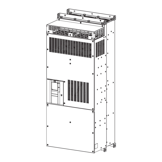
- Page 86 Outline dimension drawings Outline dimension drawings 6.3.1 Inverter outline dimension drawings FR-A862-05450 3-φ12 hole 8-φ25 hole (70) (Unit: mm) FR-A862-06470, FR-A862-08500 3-φ12 hole 8-φ25 hole (100) (Unit: mm) SPECIFICATIONS...
- Page 87 MEMO...
- Page 88 APPENDIX APPENDIX provides the reference information for use of this product. Refer to APPENDIX as required. Appendix 1 For customers replacing the conventional model with this inverter ............88 Appendix 2 Comparison with FR-A860..........90 Appendix 3 Instructions for UL and cUL .........91 Appendix 4 Restricted Use of Hazardous Substances in Electronic and Electrical Products...
- Page 89 Appendix 1 For customers replacing the conventional model with this inverter Appendix 1.1 Replacement of the FR-A700 series Difference and compatibility with FR-A700 series Item FR-A760 FR-A862 V/F control V/F control Advanced magnetic flux vector control Advanced magnetic flux vector control Control method Real sensorless vector control Real sensorless vector control...
- Page 90 Installation precautions • Removal procedure of the front cover is different. (Refer to page 15.) • Plug-in options of the FR-A700 series are not compatible. • Operation panel (FR-DU07) cannot be used. Wiring precautions • The spring clamp type terminal block has changed to the screw type. Use of blade terminals is recommended. Instructions for continuous use of the FR-PU07 (parameter unit) manufactured in September 2015 or earlier •...
- Page 91 Appendix 2 Comparison with FR-A860 Item FR-A860 FR-A862 Setting ranges "0 to 2, 10, 11, 20, 21, 100, 101, 110, Pr.30 Regenerative Setting ranges "2, 10, 11, 102, 110, 111" 111, 120, 121" Initial value "10" function selection Initial value "0" Pr.70 Special With the parameter Without the parameter...
- Page 92 Appendix 3 Instructions for UL and cUL (Standard to comply with: UL 508C, CSA C22.2 No.14) General Precaution CAUTION - Risk of Electric Shock - The bus capacitor discharge time is 10 minutes. Before starting wiring or inspection, switch power off, wait for more than 10 minutes, and check for residual voltage between terminal P/+ and N/- with a meter etc., to avoid a hazard of electrical shock.
- Page 93 Appendix 4 Restricted Use of Hazardous Substances in Electronic and Electrical Products The mark of restricted use of hazardous substances in electronic and electrical products is applied to the product as follows based on the “Management Methods for the Restriction of the Use of Hazardous Substances in Electrical and Electronic Products”...
- Page 94 WARRANTY When using this product, make sure to understand the warranty described below. 1. Warranty period and coverage We will repair any failure or defect (hereinafter referred to as "failure") in our FA equipment (hereinafter referred to as the "Product") arisen during warranty period at no charge due to causes for which we are responsible through the distributor from which you purchased the Product or our service provider.
- Page 95 • The copyright and other rights of the enclosed CD-ROM all belong to Mitsubishi Electric Corporation. • No part of the enclosed CD-ROM may be copied or reproduced without the permission of Mitsubishi Electric Corporation. • Specifications of the enclosed CD-ROM are subject to change for modification without notice.
- Page 96 MEMO...
- Page 97 REVISIONS *The manual number is given on the bottom left of the back cover. Print Date *Manual Number Revision May 2016 IB(NA)-0600639ENG-A First edition IB(NA)-0600639ENG-A...
- Page 98 HEAD OFFICE: TOKYO BUILDING 2-7-3, MARUNOUCHI, CHIYODA-KU, TOKYO 100-8310, JAPAN IB(NA)-0600639ENG-A(1605)MEE Printed in Japan Specifications subject to change without notice.
Need help?
Do you have a question about the FR-A862-05450-E and is the answer not in the manual?
Questions and answers