
Subscribe to Our Youtube Channel
Related Manuals for SBC PCD7.LR P5 Series


Summary of Contents for SBC PCD7.LR P5 Series
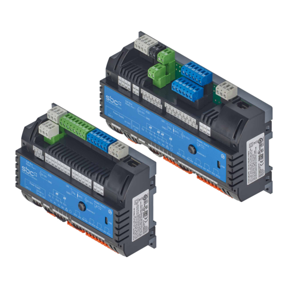
- Page 1 Manual PCD7.LRxx-P5 Saia PG5 programmable ® room controller Document 27-653; version ENG07 | 2019-03-21...
-
Page 2: Table Of Contents
Saia-Burgess Controls AG Table of contents Manual PCD7.LRxx-PG5 Table of contents Document history ..................0-5 Trademarks ....................0-5 Graphic overview Go to ......................1-1 PCD7.LRL2-P5 (230 V AC) ............... 1-2 PCD7.LRL4-P5 (230 V AC) ............... 1-3 PCD7.LRL5-P5 (24 V AC) ................. 1-4 PCD7.LRS4-P5 (230 V AC) ............... - Page 3 Saia-Burgess Controls AG Table of contents Manual PCD7.LRxx-PG5 3.1.5 Removal from mounting rails ..............3-5 3.1.6 Wall mounting .................... 3-6 3.1.7 Removal from the wall ................3-6 Electrical data .................... 3-7 3.2.1 PCD7.LRL2-P5, -.LRL4-P5 and -.LRS4-P5 (230 VAC models) ....3-7 3.2.2 PCD7.LRL5-P5 and PCD7.LRS5-P5 (24 VAC) .........
- Page 4 AOx - Analogue outputs ................4-22 Connection examples ................4-23 Communication interfaces PGU (Micro-USB port) programming interface .......... 5-2 Using the SBC S-Bus protocol ..............5-3 RS-485 interfaces (ports 0 + 1) in general ..........5-4 5.3.1 Schematic diagram of a PCD7.LRxx-P5 room controller in an RS-485 bus with terminating resistors ..........
- Page 5 Saia-Burgess Controls AG Table of contents Manual PCD7.LRxx-PG5 Room operating devices Overview of room operating devices ............7-2 Sylk bus FBoxes ..................7-4 7.2.1 Initialising the Sylk bus interface ..............7-4 7.2.2 PCD7.LR-TR40-xxx wall device without LC display ........7-5 7.2.3 PCD7.LR-TR42-xxx wall device with LC display ........
-
Page 6: Document History
Saia-Burgess Controls AG Table of contents Manual PCD7.LRxx-PG5 Document history Version Changed Published Chapter Remarks ENG02 2018-06-07 2018-06-07 Manual - New document ENG03 2018-07-17 2018-07-17 5.3.5.6 - Modbus specification added ENG04 2018-09-21 2018-09-21 3.2.2 - MaxPower consumption in W - C orex in table “input properties” 4.2.3 - Programming - C orex Modbus specification... -
Page 7: Graphic Overview
Saia-Burgess Controls AG Graphic overview Go to .. Graphic overview Go to .. PCD7.LRL2-P5 (230 V AC) PCD7.LRL4-P5 (230 V AC) PCD7.LRL5-P5 (24 V AC) PCD7.LRS4-P5 (230 V AC) PCD7.LRS5-P5 (24 V AC) Go to .. The graphic overviews show some of the most important points in the operating instructions. -
Page 8: Pcd7.Lrl2-P5 (230 V Ac)
Saia-Burgess Controls AG Graphic overview Go to .. PCD7.LRL2-P5 (230 V AC) Port 1 (RS-485) 6 universal inputs Sylk bus Port 0 (RS-485) 2 analogue outputs 26 27 28 29 30 31 32 34 44 46 48 52 54 62 63 64 33 35 45 47 49 53 55... -
Page 9: Pcd7.Lrl4-P5 (230 V Ac)
Saia-Burgess Controls AG Graphic overview Go to .. PCD7.LRL4-P5 (230 V AC) 10 universal inputs Port 1 (RS-485) Sylk bus Port 0 (RS-485) 6 analogue outputs 26 27 28 29 30 31 32 34 36 38 40 42 46 48 52 54 56 58 60 62 63 64 33 35 37 39 41 43... -
Page 10: Pcd7.Lrl5-P5 (24 V Ac)
Saia-Burgess Controls AG Graphic overview Go to .. PCD7.LRL5-P5 (24 V AC) 10 universal inputs Port 1 (RS-485) Sylk bus Port 0 (RS-485) 6 analogue outputs 26 27 28 29 30 31 32 34 36 38 40 42 46 48 52 54 56 58 60 62 63 64 33 35 37 39 41 43... -
Page 11: Pcd7.Lrs4-P5 (230 V Ac)
Saia-Burgess Controls AG Graphic overview Go to .. PCD7.LRS4-P5 (230 V AC) Port 1 (RS-485) 4 universal inputs Sylk bus 4 analogue outputs Port 0 (RS-485) 20 21 22 26 27 28 29 30 31 32 33 34 35 36 37 38 39 40 41 23 24 25... -
Page 12: Pcd7.Lrs5-P5 (24 V Ac)
Saia-Burgess Controls AG Graphic overview Go to .. PCD7.LRS5-P5 (24 V AC) Port 1 (RS-485) 4 universal inputs Sylk bus Port 0 (RS-485) 4 analogue outputs 20 21 22 26 27 28 29 30 31 32 33 34 35 36 37 38 39 40 41 23 24 25... -
Page 13: General Guidance
Saia-Burgess Controls AG General guidance General guidance Information on how to use this manual Documents Scope of supply Recommended installation material IP30 protective terminal covers (optional) Disposal Information for commissioning Introduction Wiring 2.10 Programming 2.11 Installation information for room operating devices Hardware manual PCD7.LRxx-PG5 room controller │... -
Page 14: Information On How To Use This Manual
Saia-Burgess Controls AG General guidance Information on how to use this manual Information on how to use this manual This manual describes the technical details of the components. The meaning of the symbols and abbreviations used in this manual and general technical informa- tion can be found in the Appendix. -
Page 15: Documents
Saia-Burgess Controls AG General guidance Documents Documents Comprehensive information and downloadable manuals, flyers, etc. can be found on the following websites. Support: www.sbc-support.com PCD homepage: www.saia-pcd.com The following documents are recommended as supplements to this manual: Subject Document number Data sheets PCD7LRxx-P5 PG5 Room Controller PP31-405 PCD7.LR-TR42x Wall Modules PP31-409 Q.RCU-A-xxxx Analogue Room Control Unit... -
Page 16: Package Contents
Saia-Burgess Controls AG General guidance Package contents Package contents Package contents PCD7.LRxx-P5 device Plastic bag with connectors Installation instructions Not included, but required for commissioning etc. Connecting cable between PCD7.LRxx-P5 device and PC USB A male to Micro-USB B male Power supply for the PCD7.LRxx-P5 device Saia PG5®... -
Page 17: Tips For Unpacking
Saia-Burgess Controls AG General guidance Recommended installation material 2.3.2 Tips for unpacking PCD7.LRLx-P5 PCD7.LRSx-P5 26 27 28 29 30 31 32 34 36 38 40 42 46 48 52 54 56 58 60 62 63 64 20 21 22 26 27 28 29 30 31 32 33 34 35 36 37 38 39 40 41... -
Page 18: Recommended Installation Material
Saia-Burgess Controls AG General guidance Recommended installation material Recommended installation material Pieces Description Screws for wall mounting (screws as per DIN EN ISO 7049 – ST4.2x22 - C - H) Screws for mounting the protective terminal covers (screws as per DIN EN ISO 7049 – ST2.9x9.5 - C (F) - H) Mounting rail as per DIN EN 60715 TH35 Cable ties (width max. 3 mm) for affixing cables to the bottom of the Cables... -
Page 19: Ip30 Protective Terminal Covers (Optional)
Saia-Burgess Controls AG General guidance IP30 protective terminal covers (optional) IP30 protective terminal covers (optional) If the controllers are installed outside a control cabinet, the protective terminal covers must be mounted before being connected to the device’s power supply in order to achieve IP30 conformity. -
Page 20: Disposal
Saia-Burgess Controls AG General guidance Disposal Disposal WEEE Directive 2012/19/EC Waste Electrical and Electronic Equipment directive At the end of the product life dispose of the packaging and product in a corresponding recycling centre. Do not dispose of the unit with the usual domestic refuse. Do not burn the product ! Hardware manual PCD7.LRxx-PG5 room controller │... -
Page 21: Information For Commissioning
Saia-Burgess Controls AG General guidance Information for commissioning Information for commissioning 2.7.1 Safety information To ensure safe operation, the PCD7.LRxx-P5 room controllers must only be op- erated by qualified personnel in accordance with the information in the operating instructions and in accordance with the technical data provided. Qualified person- nel are persons who are trained in the installation, commissioning and operation of these devices and have the appropriate qualifications for this work. -
Page 22: Introduction
Saia-Burgess Controls AG General guidance Introduction Introduction 2.8.1 Overview Freely programmable room automation solution with two serial ports for S-Net or Modbus master or slave communication and up to 24 inputs/outputs. Model overview Item number PCD7.LRL2-P5 Large 230 VAC max. 300 mA ... -
Page 23: Room Hvac Sample Application Template
Saia-Burgess Controls AG General guidance Introduction 2.8.2 Room HVAC sample application template There is a room HVAC sample application template for the PCD7.LRxx-P5 room control- ler, which can be used as a starting point for 1 ... 3 the following applications: VarSpeed 1 ... -
Page 24: Legacy Pcd7.L60X-1 Room Controller Emulation
L60x register (= addresses used by the L60x) to the FBoxes in the room application, or vice versa. For more detailed information, please refer to the separate document for the manual room template, found at www.sbc-support.com. 2-12 Hardware manual PCD7.LRxx-PG5 room controller │ Document 27-653; version ENG07 │ 2019-03-21... -
Page 25: System Compatibility
Saia-Burgess Controls AG General guidance Introduction 2.8.4 System compatibility The following versions are recommended for optimal FBox library use with PG5: ● PG5 >= V2.3.113 ● Firmware PCD7.LRxx-xx (IRM) >= 1.1.0.07 ● Firmware PCD (PCD plus system) >= 1.26.xx ● Firmware PCD (PCD system) >= 1.24.67 ●... - Page 26 Saia-Burgess Controls AG General guidance Introduction in FBoxes that can be modified during operation (“online parameters”) and adds them to a list of parameters to be backed up and restored. When the program is downloaded, the FBox detects that the CRC has been changed and backs up the adjustment parameters. A restore operation is carried out at power-up, cold start/restart or if the same program is downloaded again.
- Page 27 Saia-Burgess Controls AG General guidance Introduction Image: S_Adjust_Max If this happens, the program cannot be built and downloaded. The number of parameters to be backed up/restored must be reduced. 2-15 Hardware manual PCD7.LRxx-PG5 room controller │ Document 27-653; version ENG07 │ 2019-03-21...
-
Page 28: Wiring
Saia-Burgess Controls AG General guidance Wiring Wiring Appropriate use by trained personnel ● The PCD7.LRxx-P5 room controllers have slots under their terminals for cable ties to secure cables and provide strain relief. max. 9 mm max. 3 mm ● 230 VAC supply lines and data lines must be wired separately with a minimum distance of 10 cm between them. -
Page 29: Overvoltage Protection For Large Distances Or External Lines
Saia-Burgess Controls AG General guidance Programming 2.9.1 Overvoltage protection for large distances or external lines ● When laying lines outside buildings or across large distances, suitable overvolt- age measures must be implemented. These measures are especially crucial for bus lines. ●... -
Page 30: Programming
Saia-Burgess Controls AG General guidance Programming 2.10 Programming The PCD7.LRxx-P5 room controllers are programmed with Saia PG5 directly over ® Micro-USB or over an S-Bus Master Gateway controller via S-Bus. Programming directly via USB 20 21 22 26 27 28 29 30 31 32 33 34 35 36 37 38 39 40 41... -
Page 31: Installation Information For Room Operating Devices
Saia-Burgess Controls AG General guidance Programming 2.11 Installation information for room operating devices ■ The room operating devices must only be installed and connected by a qualified expert as per the circuit diagram. Existing safety regulations must be observed. ■ The room operating devices are only used to control the temperature in dry, closed rooms. -
Page 32: Room Controller / Cpu
Saia-Burgess Controls AG Room controller/CPU Room controller / CPU Dimensions/device installation Electrical data Power supply and earthing concept CPU properties General technical details Firmware/operating system System memory structure System resources LEDs/operating statuses 3.10 RUN/HALT key 3.11 Watchdog (software) Hardware manual PCD7.LRxx-PG5 room controller │ Document 27-653; version ENG07 │ 2019-03-21... -
Page 33: Dimensions/Device Installation
Saia-Burgess Controls AG Room controller/CPU Dimensions/device installation Dimensions/device installation 3.1.1 Dimensions without protective terminal covers The controller is available in two IP20-compliant housing sizes: 20 21 22 26 27 28 29 30 31 32 33 34 35 36 37 38 39 40 41 42 PCD7.LRSx-P5 (small housing): 23 24 25... -
Page 34: Dimensions With Protective Terminal Covers
Saia-Burgess Controls AG Room controller/CPU Dimensions/device installation 3.1.2 Dimensions with protective terminal covers IP30-compliant protective terminal covers in large package, set of 10 individual protective covers. Two covers are required for each device: Item number: PCD7.LRSx-P5 (small housing) IRM-RSC Total external dimensions W ×... -
Page 35: Installation Position And Ambient Temperature
Saia-Burgess Controls AG Room controller/CPU Dimensions/device installation 3.1.3 Installation position and ambient temperature Normally, a horizontal or vertical surface is used for mounting the module support. Vertical mounting is preferred. In this installation position, an ambient temperature between 0°C and 50°C is permissible. In all other positions, the air flow is less favourable and an ambient temperature of 40°C must not be exceeded. 5…95% r.H. -
Page 36: Removal From Mounting Rails
Saia-Burgess Controls AG Room controller/CPU Dimensions/device installation and flush on the mounting rail. 3. Push the slide lock(s) back into the initial position until another audible click is heard. Ensure that the PCD7.LRxx-P5 is hooked in correctly and is locked into place. The room controller can then be wired. If installing vertically on a DIN rail, the device must be secured from slipping using a stop. -
Page 37: Wall Mounting
Saia-Burgess Controls AG Room controller/CPU Dimensions/device installation 3.1.6 Wall mounting The device can be mounted on any even surface in any desired posi- tion. (See also section “Ambient condition thresholds” on page 18 for temperature range restrictions LRLx-P5: 187.5 when installing on the floor or LRSx-P5: 151.5 ceiling.) 20 21 22 26 27 28 29 30 31 32 33 34 35 36 37 38 39 40 41 42... -
Page 38: Electrical Data
Saia-Burgess Controls AG Room controller/CPU Electrical data Electrical data 3.2.1 PCD7.LRL2-P5, -.LRL4-P5 and -.LRS4-P5 (230 VAC models) Power supply Terminals 1 + 2 230 VAC +10%/-15%, 50/60 Hz Max. power consumption (unloaded) Max. power consumption (loaded) 18 W The controller is “unloaded” when no external load is applied. Therefore, the only load placed on the controller is the inherent load (8 W) of the electronics them- selves. -
Page 39: Power Supply And Earthing Concept
Saia-Burgess Controls AG Room controller/CPU Power supply and earthing concept Power supply and earthing concept 3.3.1 Devices with a 230 VAC supply The controllers are supplied with power via an orange plug-in screw-type terminal block (terminals 1 + 2). See figure below. These terminals 1 and 2 support cables with 1 × 4 mm or 2 ×... -
Page 40: Devices With A 24 Vac Supply
Saia-Burgess Controls AG Room controller/CPU Power supply and earthing concept 3.3.2 Devices with a 24 VAC supply The 24 VAC models are supplied via a black removable connector (termi- nals 3 + 4) that allows the power supply adapter connection to be interlinked. See next figure. -
Page 41: Internal 24 Vac Supply Voltage Output For Auxiliary Or Field Devices
Saia-Burgess Controls AG Room controller/CPU Power supply and earthing concept 3.3.3 Internal 24 VAC supply voltage output for auxiliary or field devices The 24 VAC* auxiliary power supply terminals deliver a maximum: ► PCD7.LR5 (24 VAC): 600 mA ► PCD7.LR2 (230 VAC) PCD7.LR4 (230 VAC): 300 mA (or 320 mA for max. 2 minutes) 26 27 28 29 30 31 32 34 36 38 40 42... -
Page 42: Earthing Concept
Saia-Burgess Controls AG Room controller/CPU CPU properties 3.3.4 Earthing concept The terminal "24V0" should be connected to the earthing rail using the shortest possible cable (< 25 cm) with a cross-section of 1.5 mm 20 21 22 26 27 28 29 30 31 32 33 34 35 36 37 38 39 40 41... -
Page 43: Cpu Properties
Saia-Burgess Controls AG Room controller/CPU General technical details CPU properties Properties PCD7.LRxx General characteristics Max. number of inputs/outputs up to 24 Processor Cortex M4 Firmware, firmware update (firmware memory soldered) Can be downloaded from Saia PG5 environment ® Programmable with Saia PG5 ® from V2.3.100 User program/DB/TEXT (FLASH) 128 kB Main memory/DB/TEXT (RAM) -
Page 44: General Technical Details
Saia-Burgess Controls AG Room controller/CPU General technical details General technical details Power supply (external and internal) Supply voltage 20% / 230 V 10%/ AC ± AC + Power consumption Typically 8 W Ambient conditions Ambient temperature Vertical installation: 0…+50°C In other installation positions a reduced temperature range ap- plies: 0…+40°C Storage temperature... -
Page 45: Firmware/Operating System
System memory structure Firmware/Operating system The firmware is backed up to flash memory. A firmware update can be download- ed to the PCD7.LRxx-P5 at any time using the Saia PG5 ® To do this, proceed as follows: Go to www.sbc-support.com and download the latest firmware version. ● Connect the Saia PG5 to the controller via USB. ® ● Open the “Online Configurator” and go online. ● In the “Tools” menu, select “Firmware Downloader” and then “Browse” to select the path to the file with the new firmware version. Ensure that only one file is... -
Page 46: System Memory Structure
Saia-Burgess Controls AG Room controller/CPU System resources System memory structure Memory PCD media with Registers: 4050 FRAM technology Flag: 4050 Timer/counter: DB/text User program code 128 kB saved in file system including ROM DB/text Main memory with RAM 10 kB DB/text technology (volatile) Resources Flag 0...3999/4000../4049 mapping Timer/counter 0...399... -
Page 47: System Resources
Saia-Burgess Controls AG Room controller/CPU System resources System resources 3.8.1 User program in block structure The user program parts are stored by the programmer in blocks assigned accord- ing to their function. Type Number Addresses Remarks Cyclical organisation blocks (COB) 0...1 Main program elements Exception/system-dependent... -
Page 48: Data Types/Value Ranges
Saia-Burgess Controls AG Room controller/CPU LEDs/operating states 3.8.2 Data types/value ranges Type Area Remarks Integer -2,147,483,648 to Format: Decimal, binary, BCD or +2,147,483,647 hexadecimal IEEE single precision ±1.401 × 10 to 3.403 × 10 3.8.3 Resource elements Type Number Addresses Remarks Flags (1 bit) 4050... -
Page 49: Led/Operating States
Saia-Burgess Controls AG Room controller/CPU RUN/HALT key LED/operating states The colour LEDs indicate the possible operating statuses of the CPU, as shown in the following table. Meaning of LEDs Function Com Port #1 Com Port #0 STOP/HALT Labelling Description 20 21 22 26 27 28 29 30 31 32 33... -
Page 50: Run/Halt Key
Saia-Burgess Controls AG Room controller/CPU RUN/HALT key 3.10 RUN/HALT key 20 21 22 26 27 28 29 30 31 32 33 34 35 36 37 38 39 40 41 23 24 25 24V~ 24V~ 24V~ /DA+ /DA+ Sylk Bus AO0… UI0…... -
Page 51: Restart The Controller With Run/Halt Button
Saia-Burgess Controls AG Room controller/CPU Watchdog (software) 3.10.2 Restart the controller with RUN/HALT button Action Display Controller program is running (operation = RUN). T1 R1 T0 R0 (RUN/HALT key has not yet been pressed.) RUN/HALT key has been pressed, which has led to a program STOP. T1 R1 T0 R0 The controller indicates this with a yellow LED below the symbol consisting of an exclamation mark inside a triangle. -
Page 52: Watchdog (Software)
Saia-Burgess Controls AG Room controller/CPU Watchdog (software) 3.11 Watchdog (software) A software watchdog (in which the processor monitors itself and the CPU is re- started in the event of a malfunction or a loop) is sufficient for non-critical applica- tions. The core of the software watchdog is the STL command SYSWR K 1000, which is also used in the “Software Watchdog” FBox. -
Page 53: Inputs And Outputs
Saia-Burgess Controls AG Inputs/outputs (I/O) Inputs and outputs Connection overview and functions Universal inputs Digital outputs Analogue outputs Connection examples This section describes the inputs and outputs of the PCD7.LRxx-P5 controllers in terms of their function and terminal assignment. Please note: There is one labeling foil per housing size. Means that terminal names are present but the terminals are physically missing. -
Page 54: Connection Overview And Functions
Saia-Burgess Controls AG Inputs/outputs (I/O) Connection overview and functions Connection overview and functions PCD7.LRL2-P5 26 27 28 29 30 31 32 34 44 46 48 52 54 62 63 64 33 35 45 47 49 53 55 24V~ /DA+ 24V~ /DA+ 24V~ 24V~... - Page 55 Saia-Burgess Controls AG Inputs/outputs (I/O) Connection overview and functions PCD7.LRLx-P5 room controllers Overview of connections and functions (by model) Terminal Label Function PCD7._ _ _ _-P5 2.5 mm LRL2 LRL4 LRL5 1, 2 “L”, “N” 230 V power supply (4 mm (terminal 1 ×...
- Page 56 Saia-Burgess Controls AG Inputs/outputs (I/O) Connection overview and functions PCD7.LRS4-P5 20 21 22 26 27 28 29 30 31 32 33 34 35 36 37 38 39 40 41 23 24 25 24V~ 24V~ 24V~ /DA+ /DA+ Sylk Bus AO0… UI0…...
- Page 57 Saia-Burgess Controls AG Inputs/outputs (I/O) Connection overview and functions PCD7.LRSx-P5 room controllers Overview of connections and functions (by model) Terminal Label Function PCD7._ _ _ _-P5 2.5 mm LRS4 LRS5 “L”, “N” 1, 2 230 V power supply ─ (4 mm (terminal 1 ×...
- Page 58 Saia-Burgess Controls AG Inputs/outputs (I/O) Universal inputs UIx - Universal inputs PCD7LRLx-P5 PCD7LRSx-P5 20 21 22 26 27 28 29 30 31 32 33 34 35 36 37 38 39 40 41 27 28 29 30 31 32 34 36 38 40 42 46 48 52 54 56 58 60 62 63 64...
- Page 59 Saia-Burgess Controls AG Inputs/outputs (I/O) Universal inputs Universal input Properties, types and PG5 Device Configurator settings Type Type PG5 Device Configurator Properties settings 0…10 V 0…10 V 2.5 kΩ 2.5 kΩ 10 kΩ 0…10 kΩ 100 kΩ (NTC 20 kΩ) and (NTC 10 kΩ) 0…100 kΩ PT/NI 1000 PT/NI 1000 L&S Dry contact closed: Resistance < 10 kΩ dry contact open: Resistance > 20 kΩ Pull-up voltage: 10 V Digital Input 24 VDC Input delay: min.
-
Page 60: Use As Digital Inputs
Saia-Burgess Controls AG Inputs/outputs (I/O) Universal inputs 4.2.1 Use as digital inputs ● Digital input 24 VDC with source operation ● Digital input 24 VDC with sink operation ● Digital input as dry contact 4.2.1.1 Digital input 24 VDC with source operation PCD7.LRxx-P5 Mode selection Connection example... -
Page 61: Device Configuration For Defining Digital Inputs
Saia-Burgess Controls AG Inputs/outputs (I/O) Universal inputs 4.2.1.4 Device configuration for defining digital inputs The digital input mode is selected using the PG5 “Device Configurator”. Hardware manual PCD7.LRxx-PG5 room controller │ Document 27-653; version ENG07 │ 2019-03-21... -
Page 62: Programming Digital Inputs
Saia-Burgess Controls AG Inputs/outputs (I/O) Universal inputs Media mapping of UI if they are used as digital inputs Mapping to flags is possible since FW 1.10.07 and PG5 2.3.161 Accessible via PG5 Device Configurator > Menu > View > Media mapping window or ALT + F5. Overview of the flag status in relation to the usage of the UI Usage Status of Status of flag flag If contact If contact PCD7.LRxx-P5 is open is closed DI as dry contact Dry contact (GND on UI) PCD7.LRxx-P5... -
Page 63: Use As Analogue Inputs
Saia-Burgess Controls AG Inputs/outputs (I/O) Universal inputs 4.2.2 Use as analogue inputs ● Analogue input with 0…10V ● Analogue input as resistance measurement ● Analogue input as temp. measurement 4.2.2.1 Analogue input with 0…10V Mode selection Connection example PCD7.LRxx-P5 Device Configurator AI with 0..10V 0 ... -
Page 64: Configuring Analogue Input Channels
Saia-Burgess Controls AG Inputs/outputs (I/O) Universal inputs 4.2.2.4 Configuring analogue input channels Same as chapter «4.2.3 UIx - Device configuration for defining digital inputs» 4-12 Hardware manual PCD7.LRxx-PG5 room controller │ Document 27-653; version ENG07 │ 2019-03-21... - Page 65 Saia-Burgess Controls AG Inputs/outputs (I/O) Universal inputs Overview of the accuracy of analogue inputs in relation to the mode. Mode Accuracy Display (with TAmbient = 25°C) Voltage 0 … 10 V +/– 100 mV 0 … 10000 Resistance 0 … 2 .5 kΩ +/– 0.7 % +/– 5 Ω...
-
Page 66: Programming Analogue Inputs
Saia-Burgess Controls AG Inputs/outputs (I/O) Universal inputs 4.2.2.5 Programming analogue inputs The mapped registers of the universal inputs, configured as analogue inputs, could be used as common in the program application. For NTC 10k temperature sensors, the conversion FBox could be used. Conversion tables for NTC 10k and NTC 20k are available on appendix A.4.2. Conversion FBoxes 4.2.2.6 Definitions of range, over/under-range and status flag... -
Page 67: Status Registers
Saia-Burgess Controls AG Inputs/outputs (I/O) Universal inputs 4.2.2.7 Status registers An analogue value may exceed or fall below the defined value. In order for the program to detect this, the “IO.UniversalInputStatus” registers are used. An “IO.UniversalInputStatus” register contains four bytes, where each byte stands for the status of an analogue input exceeding or falling below the defined value. When there are more than four analogue inputs per system, more “IO.UniversalInputStatus” registers are used in proportion to the number of inputs. The registers are thus counted up from the address number 0 in the process. IO.UniversalInputStatus0 (R with 4 bytes = status of 4 analogue inputs) IO.UniversalInputStatus1 (R with 4 bytes = status of 4 analogue inputs) ... -
Page 68: Rox/Tox - Digital Outputs
Saia-Burgess Controls AG Inputs/outputs (I/O) Digital outputs ROx/TOx - Digital outputs VDE guidelines do not permit different operating voltages to be mixed on relays and triacs. 26 27 28 29 30 31 32 34 36 38 40 42 46 48 52 54 56 58 60 62 63 64 20 21 22 26 27 28 29 30 31 32 33 34 35 36 37 38 39 40 41... - Page 69 Saia-Burgess Controls AG Inputs/outputs (I/O) Digital outputs Property Type 1 Type 2 PCD7 PCD7. LRLx-P5 LRSx-P5 (standard) (high switch-on current) 70,000 cycles 100,000 cycles Electrical endurance 4 A at 250 VAC 10 A at 250 VAC (cosφ =1) (cosφ =1) Switching of light, fan motor Application Fan motor, light and electrical heater...
-
Page 70: Tox - Triac Outputs
26 27 28 29 30 31 32 34 36 38 40 42 46 48 52 54 56 58 60 62 63 64 20 21 22 26 27 28 29 30 31 32 33 34 35 36 37 38 39 40 41 Saia-Burgess Controls AG Inputs/outputs (I/O) 33 35 37 39 41 43... -
Page 71: Connection Examples For Triac Outputs
Saia-Burgess Controls AG Inputs/outputs (I/O) Digital outputs 4.3.4 Connection examples for Triac Outputs 26 27 28 29 30 31 32 34 36 38 40 42 46 48 52 54 56 58 60 62 63 64 33 35 37 39 41 43 47 49 53 55 57 59 61 4.3.4.1... -
Page 72: Triac Outputs 24Vac Internal Powered
Saia-Burgess Controls AG Inputs/outputs (I/O) Digital outputs 26 27 28 29 30 31 32 34 36 38 40 42 46 48 52 54 56 58 60 62 63 64 4.3.4.2 Triac outputs 24VAC internal powered 33 35 37 39 41 43 47 49 53 55 57 59 61 Switching currents for the triac outputs are supplied by the controller’s internal... -
Page 73: Triac Outputs 230Vac External Power Supply
Saia-Burgess Controls AG Inputs/outputs (I/O) 26 27 28 29 30 31 32 34 36 38 40 42 46 48 52 54 56 58 60 62 63 64 Digital outputs 33 35 37 39 41 43 47 49 53 55 57 59 61 4.3.4.3 Triac outputs 230VAC external power supply 24V~... -
Page 74: Aox - Analogue Outputs
Saia-Burgess Controls AG Inputs/outputs (I/O) Analogue outputs AOx - Analogue outputs PCD7LRLx-P5 PCD7LRSx-P5 26 27 28 29 30 31 32 34 36 38 40 42 46 48 52 54 56 58 60 62 63 64 20 21 22 26 27 28 29 30 31 32 33 34 35 36 37 38 39 40 41... -
Page 75: Connection Examples
Saia-Burgess Controls AG Inputs/outputs (I/O) Connection examples Connection examples The following two examples show possible connections for the large and small controllers. TR42 ! Note grounding concept ! Wall module see „27-653 Manual IRM-PG5“ ANALOG OUTPUT UNIVERSAL INPUTS ANALOG DIGITAL signal source 0…10 V Sylk... - Page 76 Saia-Burgess Controls AG Inputs/outputs (I/O) Connection examples OUTPUTS ! Note grounding concept ! PCD7.LR-TR42 Q.RCU-A-TSOF analog see „27-653 Manual IRM-PG5“ room operating devices WALL MODULE UNIVERSAL INPUTS TEMP SETUP analog digital Sylk RS-485 RS-485 Port 1 Port 0 24 V~ /DA+ DB- /DA+ DB- 24 V~...
-
Page 77: Communication Interfaces
Saia-Burgess Controls AG Communication Communication interfaces PGU (Micro-USB port) programming interface Using the SBC S-Bus protocol RS-485 interfaces (ports 0 + 1) in general Modbus on PCD7.LRxx-P5 RS-485 interfaces Sylk bus The term “communication interface” will be referred to as a “port” starting from this point in this manual, for the sake of simplicity. -
Page 78: Pgu (Micro-Usb Port) Programming Interface
Saia-Burgess Controls AG Communication PGU (Micro-USB port) programming interface 24V~ 24V~ /DA+ PGU (Micro-USB port) programming interface AO0… UI0… RS485 / Port 0 /D A + 0-10V Dig. 0-10 V D B - Connector: Micro-USB type B (device connector) RUN/HALT Standard: USB 1.1 device (slave), TN T~ TO0 TN TO1... -
Page 79: Using The Sbc S-Bus Protocol
Saia-Burgess Controls AG Communication Using the SBC S-Bus protocol Using the SBC S-Bus protocol The SBC S-Bus stands for the proprietary communication protocol of the Saia . More information can be found in the manual ® “26-739_DE_Handbuch_SBC-SBus.pdf”. The SBC S-Bus is essentially designed for communication with the engineering and debugging tools, as well as connecting management levels/process control systems/room controllers. -
Page 80: Rs-485 Interfaces (Ports 0 + 1) In General
Saia-Burgess Controls AG Communication RS-485 interfaces (ports 0 + 1) in general RS-485 interfaces (ports 0 + 1) in general Up to two RS-485 interfaces can be used independently without additional hard- ware. S-Bus and Modbus communication modes can be implemented via port 0 and/or port 1. -
Page 81: Schematic Diagram Of A Pcd7.Lrxx-P5 Room Controller In An Rs-485 Bus With Terminating Resistors
20 21 22 /DA+ 26 27 28 29 30 31 32 33 34 35 36 37 38 39 40 41 42 Saia-Burgess Controls AG Communication Sylk Bus AO0… UI0… RS485 / Port 0 RS485 / Port 1 /D A + 0-10V Dig. -
Page 82: Bus Cable For Serial S-Net (S-Bus/Rs-485)
Middle stations More details on topics such as cable quality etc. can be found in “26-740_Manual_RS-485-Components” (available at www.sbc-support.com) 5.3.2 Bus cable for serial S-Net (S-Bus/RS-485) A two-wire, twisted and shielded bus cable with cable strands of at least 0.5 mm must be used. -
Page 83: Requirements For The S-Bus (Rs-485) Shielding
Saia-Burgess Controls AG Communication RS-485 interfaces (ports 0 + 1) in general 5.3.3 Requirements for the S-Bus (RS-485) shielding The shielding for each S-Bus segment can only be connected to the electrical system ground at one point. The following shows an example using a PCD3 as a master station. -
Page 84: Interface Port 1
Saia-Burgess Controls AG Communication RS-485 interfaces (ports 0 + 1) in general 5.3.5 RS-485 interface port 1 Port 1 is recommended, among other things, as an I/O extension and a connection for room operating devices. 5.3.5.1 Sample system architecture for I/O extension A second RS-485 interface can be used to connect E-Line RIO modules for I/O extension for HVAC, light or shade control. - Page 85 Saia-Burgess Controls AG Communication RS-485 interfaces (ports 0 + 1) in general Resource requirement for different E-Line modules (FBoxes) on a master PCD7. LRxx-P5 room controller: E-Line functions Program Size of RAM Registers Flags DB RAM (FBoxes) size data blocks [Lines] * [Byte] EL + S-Bus master 2064 PCD1.A1000 1753 PCD1.A2000 1493 PCD1.B1000...
- Page 86 Saia-Burgess Controls AG Communication RS-485 interfaces (ports 0 + 1) in general Example 1: What is the resource requirement for a network with a PCD7.LRxx-P5 room controller with one: 1 HVAC (for one zone) room template application 1 PCD7.LRxx-P5 room controller 2...
-
Page 87: Recommendations For Use With Lighting Or Blind Control
Saia-Burgess Controls AG Communication RS-485 interfaces (ports 0 + 1) in general Example 2: What is the resource requirement for a network with a PCD7.LRxx-P5 room controller with four HVAC room template applications (for four zones): 4 HVAC (for four zone) room template application 1... - Page 88 Saia-Burgess Controls AG Communication RS-485 interfaces (ports 0 + 1) in general Enabling the manual operating level for the E-Line modules would require additional telegrams, thus limiting the maximum number of E-Line modules to two to still be able to achieve the 250 ms response times. If manual commands are nevertheless required, “read cyclically” should be config- ured instead of “continuous”.
-
Page 89: Dali With E-Line (Pcd1.F2611-C15 Module)
PLC program. The “DALI E-Line driver” library is con- tained in the “DALI F26xx driver” library. Only smaller DALI controls can be im- plemented with the PCD1.F2611-C15 E-Line DALI module. Further information, including which FBoxes are supported, “Getting started”, etc., can be found on our support page www.sbc-support.com. 5-13 Hardware manual PCD7.LRxx-PG5 room controller │ Document 27-653; version ENG07 │ 2019-03-21... -
Page 90: Modbus On Pcd7.Lrxx-P5 Rs-485 Interfaces
Saia-Burgess Controls AG Communication Modbus on PCD7.LRxx-P5 RS-485 interfaces Modbus on PCD7.LRxx-P5 RS-485 interfaces Supported Modbus protocol Modbus/RTU Supported Modbus functionality Modbus client and Modbus server Supported baud rates 1.2 kbps, 2.4 kbps, 4.8 kbps, 9.6 kbps, 19.2 kbps, 38.4 kbps, 57.6 kbps, 115.2 kbps Supported data formats 8-N-1... -
Page 91: Addressing
Saia-Burgess Controls AG Communication Modbus on PCD7.LRxx-P5 RS-485 interfaces 5.4.2 Addressing Coils You can use standard Modbus functions 1 and 15 for reading/writing media flags, using the same address. This means the PCD FBox read/write BIN just reads/writes flags at the given ad- dress. Modbus coils (C0..C4040) are mapped to PCD Flags (F0..F4040) Modbus Coils Address PCD Flags Address … … C4040 F4040 Holding Registers The media register area is seen by Modbus as an array of 16-bit holding registers. - Page 92 Saia-Burgess Controls AG Communication Modbus on PCD7.LRxx-P5 RS-485 interfaces E.g. the Modbus PCD FBox for a 32 bits signed integer must read on even ad- dresses (with any length value): 1. Address 0, length 1 will copy R0 in Rbase 2.
-
Page 93: Media Mapping
Saia-Burgess Controls AG Communication Modbus on PCD7.LRxx-P5 RS-485 interfaces 5.4.3 Media Mapping PCD7.LRxx-P5 The following tables are a complete and detailed view, including Modbus address- ing. Modbus-Coils / PCD-Flags PCD7.LRL2-P5 PCD7-LRL4-P5 PCD7.LRL5-P5 PCD7.LRS4-P5 PCD7.LRS5-P5 Descrip- Modbus PCD flag Modbus PCD flag Modbus PCD flag Modbus PCD flag... - Page 94 Saia-Burgess Controls AG Communication Modbus on PCD7.LRxx-P5 RS-485 interfaces Registers - PCD Variables PCD7.LRL2-P5 PCD7-LRL4-P5 PCD7.LRL5-P5 PCD7.LRS4-P5 PCD7.LRS5-P5 Descrip- Modbus Modbus Modbus Modbus Modbus register register register register register register register register register register tion address address address address address address address address...
- Page 95 Saia-Burgess Controls AG Communication Modbus on PCD7.LRxx-P5 RS-485 interfaces Registers - Analogue Outputs PCD7.LRL2-P5 PCD7-LRL4-P5 PCD7.LRL5-P5 PCD7.LRS4-P5 PCD7.LRS5-P5 Analogue Modbus Modbus Modbus Modbus Modbus Output register register register register register register register register register register address address address address address address address address...
- Page 96 Saia-Burgess Controls AG Communication Modbus on PCD7.LRxx-P5 RS-485 interfaces PCD7.LRxx-P5 read Modbus values from PCD1/2/3 PCD 1/2/3 PCD7.LRxx-P5 Media mapping on the PCD 1/2/3 acting as PCD7.LRxx-P5 acting as Modbus client, reading 16-bit or 32-bit values from the server. Modbus server Example: if client reads out 12 Modbus objects, where the content of the Modbus objects is defined as 11112222 hex for HR0 / HR1,...
- Page 97 Saia-Burgess Controls AG Communication Modbus on PCD7.LRxx-P5 RS-485 interfaces PCD 1/2/3 write Modbus values to PCD7.LRxx-P5 PCD 1/2/3 PCD7.LRxx-P5 PCD 1/2/3 acting as Modbus Media mapping on the PCD7.LRxx-P5 acting as Modbus server: client and writing 16-bit or 32-bit Example: if client writes 12 Modbus objects, where the content of the PCD register on the client is defined as values to the PCD7.LRxx-P5 11112222 hex for PCD Reg 33334444 hex for PCD Reg +1 …...
- Page 98 Saia-Burgess Controls AG Communication Modbus on PCD7.LRxx-P5 RS-485 interfaces PCD7.LRxx-P5 write Modbus values to PCD 1/2/3 PCD7.LRxx-P5 PCD 1/2/3 PCD7.LRxx-P5 acting as Media mapping on the PCD 1/2/3 acting as Modbus server: Modbus client and writing 16-bit Example: if client writes 12 Modbus objects, where the content of the PCD register on the client is defined as or 32-bit values to the PCD 1/2/3 11112222 hex for PCD Reg 33334444 hex for PCD Reg +1 …...
-
Page 99: Sylk Bus
Saia-Burgess Controls AG Communication Sylk bus Sylk bus Sylk-Bus 20 21 22 26 27 28 29 30 31 32 33 34 35 36 37 38 39 40 41 23 24 25 24V~ 24V~ 24V~ /DA+ /DA+ Sylk Bus AO0… UI0… RS485 / Port 0 RS485 / Port 1 0-10V... -
Page 100: Recommendations Regarding The Pcd7.Lr-Tr40X/Tr42X Wall Modules
Saia-Burgess Controls AG Communication Sylk bus 5.5.2 Recommendations regarding the PCD7.LR-TR40x/TR42x wall modules Sylk Bus-capable devices (e.g. the TR40x/T42x) can be connected to the control- ler’s Sylk Interface. PCD7.LRSx: terminals 20 and 21 PCD7.LRLx: terminals 30 and 31 20 21 22 26 27 28 29 30 31 32 33 34 35 36 37 38 39... -
Page 101: Configuration
Saia-Burgess Controls AG Configure Configuration (PG5 Device Configurator) 6.1 The “Device Configurator” program 6.2 Using the Device Configurator Hardware manual PCD7.LRxx-PG5 room controller │ Document 27-653; version ENG07 │ 2019-03-21... -
Page 102: The Pg5 "Device Configurator" Program
Saia-Burgess Controls AG Configure The PG5 “Device Configurator” program 6.1 The PG5 “Device Configurator” program This PG5 program can be used to configure devices. The “Device Configurator” window (default view) 6.1.1 Requirement for operation The following description assumes you are familiar with the PG5 software. Information on the PG5 software, programming, tools, etc. can be found in the manual “26-732_ENG_Manual_PG5”. Manuals are never as up-to-date as the help pages for the relevant PG5 suite tool. - Page 103 Saia-Burgess Controls AG Configure Using the Device Configurator Hardware manual PCD7.LRxx-PG5 room controller │ Document 27-653; version ENG07 │ 2019-03-21...
-
Page 104: Using The Device Configurator
Saia-Burgess Controls AG Configure Using the Device Configurator 6.2 Using the Device Configurator The PCD7.LRS4-P5 controller is used in this section and the following instructions. 6.2.1 Starting the Device Configurator The Device Configurator must be used to set up hardware configurations and protocols and to determine how I/Os are handled. The program is started by double-clicking on “Device Configurator” in the project folder tree. 6.2.2 Help for the Device Configurator Help for the Device Configurator can be found in the menu “Help” “Help Topics”:... -
Page 105: Media Mapping View
Saia-Burgess Controls AG Configure Using the Device Configurator 6.2.3 Media mapping view Media mapping is the process of assigning digital and analogue I/O electronics to flags and registers in the software using a table. Example of a media mapping view To be able to view the relevant information regarding media mapping for the re- sources in question, the associated window must be opened. -
Page 106: Digital/Analogue Universal Inputs
Saia-Burgess Controls AG Configure Using the Device Configurator 6.2.4 Digital/analogue universal inputs Each of the universal inputs can be configured as follows: Mapping table for universal inputs Hardware manual PCD7.LRxx-PG5 room controller │ Document 27-653; version ENG07 │ 2019-03-21... - Page 107 Saia-Burgess Controls AG Configure Using the Device Configurator Universal input Properties, types and PG5 Dev. Config. Settings Type Type PG5 Device Configurator Properties Settings 0…10 V 0…10 V 2.5 kΩ 2.5 kΩ 10 kΩ 0…10 kΩ 100 kΩ (NTC 20 kΩ) and (NTC 10 kΩ 0…100 kΩ PT/NI 1000 PT/NI 1000 L&S Dry contact Dry contact Closed: Resistance < 10 kΩ Open: Resistance > 20 kΩ Pull-up voltage: 10 V Digital Input 24 VDC Digital Input delay: Min.
-
Page 108: Relay Outputs
Saia-Burgess Controls AG Configure Using the Device Configurator 6.2.5 Relay outputs The relay outputs are configured as follows: Properties Number of flags Number of flags Base address for flags Base address for flags 4020 Safe state value In the event of a fault, relay open/closed contact is... Enable safe state Maintain status yes/no Mapping table for relay outputs Hardware manual PCD7.LRxx-PG5 room controller │ Document 27-653; version ENG07 │ 2019-03-21... -
Page 109: Triac Outputs
Saia-Burgess Controls AG Configure Using the Device Configurator 6.2.6 Triac outputs This type of output can be configured as follows: Properties Number of flags Number of flags Base address for flags Base address for flags 4030 Safe state value In the event of a fault, relay open/closed contact is... Enable safe state Maintain status yes/no Mapping table for triac outputs Hardware manual PCD7.LRxx-PG5 room controller │ Document 27-653; version ENG07 │ 2019-03-21... -
Page 110: Analogue Outputs
Saia-Burgess Controls AG Configure Using the Device Configurator 6.2.7 Analogue outputs Analogue outputs can be configured as follows: Properties Safe state value x In the event of a fault, 0 / 1 output is... Enable safe state x Maintain status yes/no Minimum value output x Minimum output value Maximum value output x Maximum output value 10000 Mapping table for analogue outputs... -
Page 111: Room Operating Devices
Saia-Burgess Controls AG Room operating devices Room operating devices Overview of room operating devices Sylk bus FBoxes S-Bus/Modbus room operating device on RS-485 interface Hardware manual PCD7.LRxx-PG5 room controller │ Document 27-653; version ENG07 │ 2019-03-21... -
Page 112: Overview Of Room Operating Devices
Saia-Burgess Controls AG Room operating devices Overview of room operating devices Overview of room operating devices The following room operating devices can be used together with the controller to record the room temperature, define setpoints, change the occupancy status and adjust the fan speed. Communi- cation type / Operating devices Terminal on PCD7.LRLx PCD7.LRSx... - Page 113 Saia-Burgess Controls AG Room operating devices Overview of room operating devices Furthermore, the LEDs on the PCD7.L632, Q.RCU-A-TSO and the LC display of the PCD7.LR-TR42x can be configured to provide information on the following: O verriding of the controller, e.g. by pressing the “Occupancy” key on the room operating device or by receiving a network command via the controller (see section “LEDs on room operating devices for displaying information on overrides” below).
-
Page 114: Sylk Bus Fboxes
Saia-Burgess Controls AG Room operating devices Sylk bus FBoxes Sylk bus FBoxes An FBox family is available for integrating the Sylk bus wall devices type PCD7.LR-TR40-xxx (sensor only) and PCD7.LR-TR42-xxx (with display and keys). PCD7LR-TR42-xxx The application FBox view contains the “Programmable IRM” group with a subgroup “SYLK bus”, which contains the required FBoxes: Changes are always made to FBoxes. -
Page 115: Pcd7.Lr-Tr40-Xxx Wall Device Without Lc Display
Saia-Burgess Controls AG Room operating devices Sylk bus FBoxes If a PCD7.LR-TRxx device is detected on the Sylk bus and its address is used by a PCD7.LR-TRxx FBox, the “SYLK bus” FBox sends the configuration to the wall device. With a PCD7.LR-TR40-xxx, this process is invisible, whereas with a PCD7.LR-TR42-xxx, “FILE TRANSFER” can be read on the display during config- uration. 7.2.2 PCD7.LR-TR40-xxx wall device without LC display An FBox is available for the PCD7.LR-TR40 device family. Referencing via name/ref on the “SYLK bus”... -
Page 116: Pcd7.Lr-Tr42-Xxx Wall Device With Lc Display
Saia-Burgess Controls AG Room operating devices Sylk bus FBoxes A corrective value can be set for each measured value in the Adjust window FBox. The received value from the PCD7.LR-TR40-xxx is displayed with this correction both in the “Adjust win- dow” and at the outputs. - Page 117 Saia-Burgess Controls AG Room operating devices Sylk bus FBoxes The Sylk bus address for the PCD7.LR-TRxx must be configured in the adjustment parameters. The default address is 1. If only one PCD7.LR-TRxx module is con- nected to the Sylk bus, the default values are correctly preset in the FBoxes. If multiple PCD7.LR-TRxx devices (max. four) are used, the Sylk bus address in the FBox and on the associated device must be set to the same value using the DIP switch.
- Page 118 Saia-Burgess Controls AG Room operating devices Sylk bus FBoxes The “SetPt” input represents the base setpoint. ● I f the setpoint is configured as an absolute value, this is the default value and can be adjusted by the user. The effective setpoint is displayed at the “SetPt” output. ● I f the setpoint is configured as a corrective value, the default value is 0.0 and this can be adjusted by the user. The setpoint for the input + the correction by the user is displayed at the “SetPt” output. The “xxx.Fan” inputs can be used to preset the default operating mode for the fan. The “Man” input can be used to override the manual operation of the user or reset it. The input has the same function and effect. The values at the inputs are sent to the PCD7.LR-TR42 when a value is changed.
-
Page 119: Pcd7.Lr-Tr42-Xxx "Occupancy" Lc Display Configuration
Saia-Burgess Controls AG Room operating devices Sylk bus FBoxes 7.2.3.1 PCD7.LR-TR42-xxx “Occupancy” LC display configuration The LCD of a PCD7.LR-TR42 can be configured to display the different symbols of the actual occupancy mode of the controller. The following applies in this case: “Occupied” mode CONFIGURED FOR DISPLAY OF CONFIGURED FOR DISPLAY OF ENGLISH SYMBOLS AUTO AUTO ° °... - Page 120 Saia-Burgess Controls AG Room operating devices Sylk bus FBoxes “Unoccupied” mode CONFIGURED FOR DISPLAY OF CONFIGURED FOR DISPLAY OF ENGLISH SYMBOLS AUTO AUTO °C °C OVERRIDE OVERRIDE OVERRIDE CANCEL DONE AUTO AUTO AUTO AUTO OVERRIDE °C °C CANCEL OVR OVERRIDE CANCEL OVERRIDE CANCEL DONE...
- Page 121 Saia-Burgess Controls AG Room operating devices Sylk bus FBoxes “Ready” mode CONFIGURED FOR DISPLAY OF CONFIGURED FOR DISPLAY OF ENGLISH SYMBOLS AUTO AUTO °C °C OVERRIDE OVERRIDE OVERRIDE CANCEL DONE AUTO AUTO AUTO AUTO OVERRIDE °C °C CANCEL OVR OVERRIDE CANCEL OVERRIDE CANCEL DONE...
-
Page 122: Pcd7.Lr-Tr42-Xxx "Fan" Lc Display Configuration
Saia-Burgess Controls AG Room operating devices Sylk bus FBoxes 7.2.3.2 PCD7.LR-TR42-xxx “Fan” LC display configuration is displayed, the fan is switched off. Depending on the configuration of the given application, the effective control mode for underfloor heating, radiators, ceiling heating and ceiling cooling can also be switched off. 7-12 Hardware manual PCD7.LRxx-PG5 room controller │ Document 27-653; version ENG07 │ 2019-03-21... -
Page 123: Pcd7.D1000 S-Bus/Modbus Room Operating Device On Rs-485 Interface
Data points can be read and written from the controller via S-Bus and Modbus registers. For more detailed information, please refer to the data sheet which can be found at www.sbc-support.com. Features ● Design according PEHA Dialog Aluminium ● Room temperature sensor 0…40°C ●... -
Page 124: Maintenance
Saia-Burgess Controls AG Maintenance Maintenance Maintenance-free PCD7.LRxx-P5 room controllers devices do not contain any parts that can be re- placed by the user. If hardware problems occur, the components can be sent back Saia-Burgess Controls AG (see Appendix for address). PCD7.LRxx-P5 room controllers are maintenance-free. - Page 125 Saia-Burgess Controls AG Appendix Appendix Symbols RS-485 signal level Installation regulations and relay contacts Sensor properties A.5 Approvals/certifications Glossary Contact Hardware manual PCD7.LRxx-PG5 room controller │ Document 27-653; version ENG07 │ 2019-03-21...
-
Page 126: Symbols
Saia-Burgess Controls AG Appendix Symbols Symbols In operating instructions, this symbol points the reader to further information in these instructions, in other instructions or in technical documents. No direct link to these documents is given. Instructions with this symbol must always be followed. Appropriate use by trained personnel Hardware manual PCD7.LRxx-PG5 room controller │... -
Page 127: Signal Level
Saia-Burgess Controls AG Appendix RS-485 signal level RS-485 signal level e.g. start bit mark space not active 2.5 V VOZ = 0.9 V min. VOH = 1.5 V min. (with load) … 3.6 V max. (without load) VOL = -1.5 V min. (with load) … -3.6 V max. (without load) Signal type Logical status Polarity... -
Page 128: Installation Regulations And Relay Contacts
Saia-Burgess Controls AG Appendix Installation regulations and relay contacts Installation regulations and relay contacts A.3.1 Installation regulations for switching low voltages For safety reasons, voltages of max. 50 V may be switched on this module. The safety standard concerning clearance and creepage distances between neighbouring channels is not specified for higher voltages (50...250 V) for this module. -
Page 129: Information From The Relay Manufacturers On Dimensioning The Rc Element
Saia-Burgess Controls AG Appendix Installation regulations and relay contacts A.3.3 Information from the relay manufacturers on dimensioning the RC element Contact protection networks: The purpose of contact protection networks is to suppress switch arcs (“switching sparks”) and achieve a longer service life for the contacts. Each protective network has its advantages and disadvantages. See the nearby figure for arc elimination via RC network. When switching off circuits with inductive components (e.g. relay coils and mag- netic coils), the interruption in the current at the switching contacts causes an overvoltage (self-induction voltage), which can be much higher than the operating... - Page 130 Saia-Burgess Controls AG Appendix Installation regulations and relay contacts Load Example: U = 100 V I = 1 A C is given directly as 0.1 μF R = 10 Ω (point of intersection with R curve) Hardware manual PCD7.LRxx-PG5 room controller │ Document 27-653; version ENG07 │ 2019-03-21...
-
Page 131: Sensor Properties
Saia-Burgess Controls AG Appendix Sensor properties Sensor properties A.4.1 Sensor input accuracy The internal sensor inputs of the controller support NTC10kΩ and NTC20kΩ sen- sors. The following table shows the typical minimum accuracies for the hardware and software for these temperature sensors. Sensor Typical hardware measurement errors temperature range (without sensor tolerance) °Celsius (°Fahrenheit) NTC10k... - Page 132 Saia-Burgess Controls AG Appendix Sensor properties NTC 10 kΩ Temp. Resistance Applied Temp. Resistance Applied Temp. Resistance Applied [°C] [kΩ] voltage [°C] [kΩ] voltage [°C] [kΩ] voltage 12.49 3.207 1.752 0.652 – 30 7.904 11.94 3.115 1.694 0.632 – 29 166.35 7.848 11.418...
- Page 133 Saia-Burgess Controls AG Appendix Sensor properties NTC 20 kΩ Temp. Resist- Applied Temp. Resist- Applied Temp. Resist- Applied Temp. Resist- Applied [°C] ance voltage [°C] ance voltage [°C] ance voltage [°C] ance voltage [kΩ] [kΩ] [kΩ] [kΩ] 70.2 6.76 6.72 2.07 1.11 0.425...
-
Page 134: Approvals/Certifications
Saia-Burgess Controls AG Appendix Approvals/certifications A.5 Approvals/certifications ► UL 60730-1, Automatic Electrical Controls for Household and Similar Use - Part 1: General Requirements ► CAN/CSA-E60730-1:02, Automatic Electrical Controls for Household and Simi- lar Use - Part 1: General Requirements ► UL916 (supplementary list), CSA C22.2 no. 205 ►... -
Page 135: Classification Under En 60730-1
Saia-Burgess Controls AG Appendix Approvals/certifications A.5.1 Classification under EN 60730-1 EN 60730 subsection EN 60730-2-9 Ambient conditions For use in environments in residential buildings (residential, commercial and light industry) Construction Independently-mounted controller for panel mounting Action Type 1.C Nominal pulse voltage 2500 V at 230 V, 500 V at 24 V Degree of pollution Protection against impact Class 0 (without terminal covers) -
Page 136: Glossary
Saia-Burgess Controls AG Appendix Glossary Glossary Backup Data backup on second data carrier Base address First numerical address of the I/O module slots ® Central processing unit. In the case of the Saia PCD family, this refers to the main housing with the central unit. Device Device → controller (integral part of a project in Saia PG5 ®... -
Page 137: Contact
Contact Saia-Burgess Controls AG Bahnhofstrasse 18 3280 Murten, Switzerland Telephone headquarters ..+41 26 580 30 00 Telephone SBC Support ..+41 26 580 31 00 Fax .......... +41 26 580 34 99 E-mail Support: ....... support@saia-pcd.com Support site: ......
Need help?
Do you have a question about the PCD7.LR P5 Series and is the answer not in the manual?
Questions and answers