Sign In
Upload
Manuals
Brands
SBC Manuals
Controller
PCD7.LRL2-P5
SBC PCD7.LRL2-P5 Manuals
Manuals and User Guides for SBC PCD7.LRL2-P5. We have
1
SBC PCD7.LRL2-P5 manual available for free PDF download: Manual
SBC PCD7.LRL2-P5 Manual (137 pages)
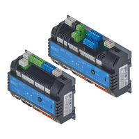
Saia PG5 programmable room controller
Brand:
SBC
| Category:
Controller
| Size: 13.23 MB
Table of Contents
Table of Contents
2
Document History
6
Trademarks
6
1 Graphic Overview
7
Go to
7
Pcd7.Lrl2-P5 (230 V Ac)
8
Pcd7.Lrl4-P5 (230 V Ac)
9
Pcd7.Lrl5-P5 (24 V Ac)
10
Pcd7.Lrs4-P5 (230 V Ac)
11
Pcd7.Lrs5-P5 (24 V Ac)
12
2 General Guidance
13
Information on How to Use this Manual
14
Documents
15
Package Contents
16
Storage Information
16
Tips for Unpacking
17
Recommended Installation Material
18
IP30 Protective Terminal Covers (Optional)
19
Disposal
20
Information for Commissioning
21
Safety Information
21
Introduction
22
Overview
22
Room HVAC Sample Application Template
23
Legacy Pcd7.L60X-1 Room Controller Emulation
24
System Compatibility
25
Addressing the Room Controllers
25
Media Backup/Restore
25
Wiring
28
Overvoltage Protection for Large Distances or External Lines
29
Addressing Inputs and Outputs (I/O)
29
Programming
30
Installation Information for Room Operating Devices
31
3 Room Controller / CPU
32
Dimensions/Device Installation
33
Dimensions Without Protective Terminal Covers
33
Dimensions with Protective Terminal Covers
34
Installation Position and Ambient Temperature
35
Installation on Mounting Rails
35
Removal from Mounting Rails
36
Wall Mounting
37
Removal from the Wall
37
Electrical Data
38
PCD7.LRL2-P5, -.LRL4-P5 and -.LRS4-P5 (230 VAC Models)
38
PCD7.LRL5-P5 and PCD7.LRS5-P5 (24 VAC)
38
Power Supply and Earthing Concept
39
Devices with a 230 VAC Supply
39
Devices with a 24 VAC Supply
40
Internal 24 VAC Supply Voltage Output for Auxiliary or Field Devices
41
Earthing Concept
42
CPU Properties
43
General Technical Details
44
Firmware/Operating System
45
System Memory Structure
46
System Resources
47
User Program in Block Structure
47
Data Types/Value Ranges
48
Resource Elements
48
Rtc/Internal Hardware Clock
48
Led/Operating States
49
RUN/HALT Key
50
Multiple Uses for the RUN/HALT Key
50
Restart the Controller with RUN/HALT Button
51
Watchdog (Software)
52
4 Inputs and Outputs
53
Connection Overview and Functions
54
Use as Digital Inputs
60
Digital Input 24 VDC with Source Operation
60
Digital Input 24 VDC with Sink Operation
60
Digital Input as Dry Contact
60
Device Configuration For Defining Digital Inputs
61
Programming Digital Inputs
62
Use as Analogue Inputs
63
Analogue Input with 0
63
Analogue Input as Resistance Measurement
63
Analogue Input as Temp. Measurement
63
Configuring Analogue Input Channels
64
Programming Analogue Inputs
66
Definitions Of Range, Over/Under-Range And Status Flag
66
Status Registers
67
Rox/Tox - Digital Outputs
68
Rox - Relay Outputs
68
Tox - Triac Outputs
70
Current Limitations for the Terminal "24 VAC out
70
Connection Examples for Triac Outputs
71
Triac Outputs 24VAC External Power Supply
71
Triac Outputs 24VAC Internal Powered
72
Triac Outputs 230VAC External Power Supply
73
Aox - Analogue Outputs
74
Connection Examples
75
5 Communication Interfaces
77
PGU (Micro-USB Port) Programming Interface
78
Using the SBC S-Bus Protocol
79
RS-485 Interfaces (Ports 0 + 1) in General
80
Schematic Diagram of a Pcd7.Lrxx-P5 Room Controller in an RS-485 Bus with Terminating Resistors
81
Bus Cable for Serial S-Net (S-Bus/Rs-485)
82
Requirements for the S-Bus (RS-485) Shielding
83
RS-485 Interface Port0
83
Interface Port 1
84
Sample System Architecture for I/O Extension
84
Limitations for I/O Extension with E-Line Modules
84
Recommendations for Use with Lighting or Blind Control
87
DALI with E-Line (PCD1.F2611-C15 Module)
89
Modbus on Pcd7.Lrxx-P5 RS-485 Interfaces
90
Limitations
90
Addressing
91
Media Mapping
93
Sylk Bus
99
Key Information about the Bus
99
Recommendations Regarding the PCD7.LR-Tr40X/Tr42X Wall Modules
100
Devices and Programming/Fboxes
100
6 Configuration
101
The PG5 "Device Configurator" Program
102
Requirement for Operation
102
General
102
Using the Device Configurator
104
Starting the Device Configurator
104
Help for the Device Configurator
104
Media Mapping View
105
Digital/Analogue Universal Inputs
106
Relay Outputs
108
Triac Outputs
109
Analogue Outputs
110
7 Room Operating Devices
111
Overview of Room Operating Devices
112
Sylk Bus Fboxes
114
Initialising the Sylk Bus Interface
114
PCD7.LR-TR40-XXX Wall Device Without LC Display
115
PCD7.LR-TR42-XXX Wall Device with LC Display
116
PCD7.LR-TR42-XXX "Occupancy" Lc Display Configuration
119
PCD7.LR-TR42-XXX "Fan" Lc Display Configuration
122
PCD7.D1000 S-Bus/Modbus Room Operating Device on RS-485 Interface
123
8 Maintenance
124
Maintenance-Free
124
A Appendix
126
Symbols
126
Signal Level
127
Installation Regulations and Relay Contacts
128
Installation Regulations for Switching Low Voltages
128
Switching Inductive Loads
128
Information from the Relay Manufacturers on Dimensioning the RC Element
129
Sensor Properties
131
Sensor Input Accuracy
131
Sensor Property Tables
131
Approvals/Certifications
134
Classification under en 60730-1
135
Classification under en 60529
135
Glossary
136
Contact
137
Advertisement
Advertisement
Related Products
SBC PCD7.LR P5 Series
SBC PCD7.LRL4-P5
SBC PCD7.LRL5-P5
SBC PCD7.LRS4-P5
SBC PCD7.LRS5-P5
SBC PCD7.L79xN
SBC PCD7.L79 Series
SBC PCD7.L790
SBC PCD7.L793
SBC PCD7.L791
SBC Categories
Cordless Telephone
Measuring Instruments
Telephone
Controller
Control Unit
More SBC Manuals
Login
Sign In
OR
Sign in with Facebook
Sign in with Google
Upload manual
Upload from disk
Upload from URL