
Related Manuals for SBC HPD N Series


Summary of Contents for SBC HPD N Series
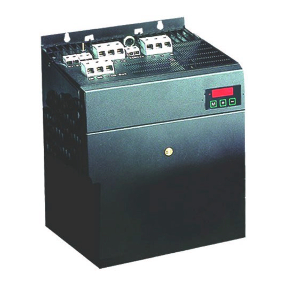
- Page 1 HPD N “high power” ( HPD25N, HPD35N, HPD45N, HPD67N ) User’s Manual rev. 8 February 2001 (software rel. 35 and later)
- Page 2 S.B.C. Elettronica S.p.A. - Engineering Division HPDxxN – High Power User’s Manual EXTENDED VOLTAGE RANGE HIGH PERFORMANCE DRIVE DIGITAL-LOCK VARIABLE RATIO POSITIONER STEP MOTOR SIMULATION EASY MAINTENANCE TORQUE CONTROL ACCELERATION CONTROL SOFTWARE & HARDWARE SPINDLE ORIENTATION EXPANSION FOR TOOL CHANGING RS-485 or RS-422 SERIAL LINK BUILT-IN P.L.C.
- Page 3 S.B.C. Elettronica S.p.A. - Engineering Division HPDxxN – High Power User’s Manual WARNING HIGH VOLTAGE ! HPD N Certain circuits in the drive carry dangerously high voltages that could cause serious personal injury or death. Do not attempt to service any parts of the drive when it is connected to the power supply. If you need to access internal parts, before working on the drive allow at least 15 minutes after power-down to allow the DC bus capacitors to discharge.
-
Page 4: Table Of Contents
S.B.C. Elettronica S.p.A. - Engineering Division HPDxxN – High Power User’s Manual CONTENTS: INTRODUCTION ................General information..................6 Product description..................6 Direct mains connection................7 Identification....................7 Main hardware characteristics..............8 Software features..................9 Compliance with EMC standards..............Safety......................9 INSTALLATION................ - Page 5 S.B.C. Elettronica S.p.A. - Engineering Division HPDxxN – High Power User’s Manual SERIAL INTERFACE ..............Communication protocol ................Serial addresses and parameter lengths ............APPENDIXES HPD N drive mechanical dimensions .............. 81 MB series motor connectors ................82 Hardware characteristics ................83 DC bus voltage thresholds ................
-
Page 6: Introduction
S.B.C. Elettronica S.p.A. - Engineering Division HPDxxN – High Power User’s Manual 1 - INTRODUCTION 1.1 General information This manual describes operations required for the installation and commissioning of the high power family HPD N (High Performance Drive – New series with extended maximum voltage range) drive for brushless motors. -
Page 7: Direct Mains Connection
HPDxxN – High Power User’s Manual 1.3 Direct mains connection The HPD N series of drives is specifically designed for direct connection to a three-phase mains power supply from 90 to 480V~ 50/60 Hz, without interposing transformers. It is the responsibility of the User to connect the system via protection fuses. -
Page 8: Main Hardware Characteristics
S.B.C. Elettronica S.p.A. - Engineering Division HPDxxN – High Power User’s Manual 1.5 Main hardware specifications Parameter u.m. Value 90..480 Mains voltage 220 + Auxiliary single-phase voltage 20 % -10 % included EMC motor filter included EMC main filter Models Rated current Peak current (30 Secs.) * 12,5... -
Page 9: Software Features
S.B.C. Elettronica S.p.A. - Engineering Division HPDxxN – High Power User’s Manual 1.6 Software features The following capabilities are implemented in the basic software supplied with the HPD N drive: • Speed control • Advanced torque limit manager • Speed windows management •... -
Page 10: Installation
S.B.C. Elettronica S.p.A. - Engineering Division HPDxxN – High Power User’s Manual 2 - INSTALLATION • The HPD N drive must be installed in a vertical position (power terminal block X4 at the top). • Leave at least 190 mm clearance above and below the drive. 2.1 Safety instructions •... -
Page 11: Interference Suppression Hints
S.B.C. Elettronica S.p.A. - Engineering Division HPDxxN – High Power User’s Manual 2.2 Interference suppression hints Because of the high speed voltage wavefronts in PWM, high levels of stray current may sometimes flow through capacitive couplings and earth systems. Stray currents of this type can affect other functional units. - Page 12 S.B.C. Elettronica S.p.A. - Engineering Division HPDxxN – High Power User’s Manual Additional measures - With the exception of mains cables to the filter, all power and control wiring must be shielded and, wherever possible, kept segregated (minimum distance 20 cm). If control and power cables must cross, the intersection must be at a right angle.
-
Page 13: Control Cubicle Layout Example
S.B.C. Elettronica S.p.A. - Engineering Division HPDxxN – High Power User’s Manual 2.4 Control cubicle layout example All conductors down-line of the mains filter must be shielded and mounted to a copper bar with large contact area. Also the copper bar must present an ample area of contact with the cubicle mounting plate. -
Page 14: Terminal Assignments
S.B.C. Elettronica S.p.A. - Engineering Division HPDxxN – High Power User’s Manual 2.5 Terminal assignments Serial Interface Resolver Encoder in Encoder out Analogue Signals and Digital Outputs Aux Voltages and Digital Inputs power connections 220Vac R1 C1 R2 C2 L1 L2 L3 AB BB-DCBUS... - Page 15 S.B.C. Elettronica S.p.A. - Engineering Division HPDxxN – High Power User’s Manual Terminal board X1 Terminal board X4 motor PTC + ( 24 V ) live 1 motor PTC - live 2 resolver Excit. high live 3 resolver Excit. low motor, phase resolver Sin high motor, phase...
-
Page 16: Power Connections
S.B.C. Elettronica S.p.A. - Engineering Division HPDxxN – High Power User’s Manual 2.6 Power connections For the motor cable consider Choice between cable for fixed or floating installation. Cable must be shielded and suitably sized in terms of insulation and wire sections. Reticulated polypropylene is the preferred insulation material. -
Page 17: Power Connection Layout
S.B.C. Elettronica S.p.A. - Engineering Division HPDxxN – High Power User’s Manual 2.7 Power connection layout MAINS -DCBUS 220 V~ MOTOR EARTH STUD RESOLVER HPD DRIVE SERVOMOTOR 2.8 Signal cable connections A twisted and shielded pair must be employed for the analogue reference. The cable for emulated encoder signals must comprise three twisted pairs with a common shield. -
Page 18: Signal Cable Connection Layout
S.B.C. Elettronica S.p.A. - Engineering Division HPDxxN – High Power User’s Manual 2.9 Signal cable connection layout MOTION CONTROLLER REF+ Reference out REF - X2 - Reference in Encoder in X7 - Encoder out 24Vdc Output 13 X3 - Inputs Enable Input X2 - Outputs... -
Page 19: Encoder Emulation
S.B.C. Elettronica S.p.A. - Engineering Division HPDxxN – High Power User’s Manual If the frequency/direction mode configuration is adopted, channel A is dedicated to frequency while channel B handles direction. Frequently, a 24V interface is preferred to an RS-422 serial port. The conversion can be implemented on the external connector by following this wiring diagram: +24V= PULSES... -
Page 20: Serial Line Connection
S.B.C. Elettronica S.p.A. - Engineering Division HPDxxN – High Power User’s Manual 2.12 Serial line connection The HPD N drive serial line can be configured as RS-422 or RS-485 depending on the connection. In both cases termination resistors must be used (150 Ω). Where more than one HPD N drive is connected to the bus the final node must be terminated as shown below. -
Page 21: Backup
S.B.C. Elettronica S.p.A. - Engineering Division HPDxxN – High Power User’s Manual 2.14 Backup When you need to keep the drive electronics powered up during mains losses, for example to maintain the simulated encoder function, certain precautions are necessary. A) Use an external 24Vdc / 2 A regulated power supply with protected output. Connect the positive pole to 8-X3 (+Vbackup) and negative pole to 9-X3 (-Vbackup). -
Page 22: Parameters And Programming
S.B.C. Elettronica S.p.A. - Engineering Division HPDxxN – High Power User’s Manual 3 - PARAMETERS AND PROGRAMMING The features: torque, speed, acceleration and position control are the task of a dedicated electronic circuits. In this chapter you can see how to set up and the meaning of any parameter, functional block diagrams and advanced functions description too. -
Page 23: Using The Keypad
S.B.C. Elettronica S.p.A. - Engineering Division HPDxxN – High Power User’s Manual 3.1 Using the keypad The keypad-display module is designed to provide an intuitive operator interface. It can be used to program operating data, monitor system status and enter commands. The module has only three keys, located at the top of the front panel just below the display. -
Page 24: Commissioning The Hpd N Drive
S.B.C. Elettronica S.p.A. - Engineering Division HPDxxN – High Power User’s Manual In addition to the parameter values and the pico-PLC instructions, the display may show the following messages: r. xx At the time of power-up this message indicates the software version installed (2 seconds approx.). - Page 25 S.B.C. Elettronica S.p.A. - Engineering Division HPDxxN – High Power User’s Manual ⋅ Pr19 = Pr33 3 The maximum value must be no higher than three times the value of Pr33 Pr29 calculation (number of poles) Use the following table for MB series motors Flange ( mm ) Pr29 Pr32 calculation (rated speed)
- Page 26 S.B.C. Elettronica S.p.A. - Engineering Division HPDxxN – High Power User’s Manual The functions on terminals 12, 13 and 14 must be enabled by setting bit b90.10 to one. This requires access to the extended parameters menu. The default PLC program controls parameter Pr5 in addition to timer 1 (Pr92) and bits b40.0, b40.4, b40.5, b40.6, b40.12 so in this case the above binary parameters and switches cannot be utilised unless the pico-PLC is disabled (b99.13=0) or the basic program is modified.
-
Page 27: Basic Parameters
S.B.C. Elettronica S.p.A. - Engineering Division HPDxxN – High Power User’s Manual 3.3 Basic parameters To access all the following parameters open the extended menu by setting b99.6 to one. For this procedure, b99.7 must be set to zero. DECIMAL PARAMETERS Motor speed: this is a read-only parameter expressed in rpm;... - Page 28 S.B.C. Elettronica S.p.A. - Engineering Division HPDxxN – High Power User’s Manual Pr12 Deceleration ramp limit-switch stop functions. Unit=s/krpm, range=0.002..65.535, resolution=0.001 s, default=0.002 s. Deceleration required of the motor by the limit-switch and stop functions is internally limited so deceleration of 1000 rpm takes Pr12 seconds Pr13 Overspeed threshold.
- Page 29 S.B.C. Elettronica S.p.A. - Engineering Division HPDxxN – High Power User’s Manual Pr25 Code describing installed software version. Read-only parameter Pr26 Serial line baud-rate code . Default=8. This is the code for programming transmission speed. For more information consult the section on the serial interface. Pr27 Serial line address code .
- Page 30 S.B.C. Elettronica S.p.A. - Engineering Division HPDxxN – High Power User’s Manual BINARY PARAMETERS Binary parameter Pb40 can be read, written and saved. Binary parameter Pb41 provides information regarding system status. Parameters Pb42 and Pb99 are read/write parameters with save facility.
- Page 31 S.B.C. Elettronica S.p.A. - Engineering Division HPDxxN – High Power User’s Manual b41.1 At speed. With b40.7=0 if the speed difference between motor and reference is lower than Pr14 and higher than Pr15, b41.1 will be 1, otherwise it will be 0. With b40.7=1, if motor speed is lower than Pr14 and higher than Pr15, b41.1 will be 1, otherwise it will be 0.
-
Page 32: Basic Commands
S.B.C. Elettronica S.p.A. - Engineering Division HPDxxN – High Power User’s Manual 3.4 Basic commands To transmit the following commands b99.7 must be on zero. For commands b42.3 and b94.1, b99.6 must be on one. b42.3 Re-initialise serial line. Command to reinitialise the serial line when the communication speed (Pr26) has been modified. - Page 33 S.B.C. Elettronica S.p.A. - Engineering Division HPDxxN – High Power User’s Manual The error value is utilised by the speed control loop to calculate (using calibration parameters) how much current to supply to the motor. TORQUE: current flowing through the motor windings is converted into torque which allows the motor to accelerate and decelerate.
- Page 34 S.B.C. Elettronica S.p.A. - Engineering Division HPDxxN – High Power User’s Manual of X2 and channel 2 to terminal 7 of X2. The V/div scale and the timebase are not mentioned as they may vary considerably. CALCULATING Pr16 The value of Pr16 should be calculated before enabling the drive. Pr16 defines system gain. To convert Pr16 into degrees for rated torque use the formula: where ac is the stiffness ac =...
- Page 35 S.B.C. Elettronica S.p.A. - Engineering Division HPDxxN – High Power User’s Manual Fig.3 The optimal value of Pr17 can be considered when system response is as shown in figure 4. Fig.4 We must therefore obtain approximately 10% overshoot. Make sure that the overshoot is not followed immediately by undershoot.
- Page 36 S.B.C. Elettronica S.p.A. - Engineering Division HPDxxN – High Power User’s Manual In certain applications you can reduce system acoustic noise levels by raising parameter Pr18 by a few points. Fig.5 shows that the optimal system response is accompanied by a current fluctuation that can generate acoustic noise and mechanical vibration;...
- Page 37 S.B.C. Elettronica S.p.A. - Engineering Division HPDxxN – High Power User’s Manual Fig.7 CALIBRATION WITHOUT INSTRUMENTS If an oscilloscope is not available, proceed as follows: A) Calculate the value of Pr16 as described earlier. B) Calculate Pr17 using the following formula: ⋅...
-
Page 38: Operating Modes
S.B.C. Elettronica S.p.A. - Engineering Division HPDxxN – High Power User’s Manual 3.6 Operating modes Operating modes are selected by means of parameter Pr31, whose default value is 0. Each operating mode commands a speed loop by means of parameter Pr6 and can limit motor torque with parameter Pr21 (see block diagrams). -
Page 39: Maintenance And Commissioning
S.B.C. Elettronica S.p.A. - Engineering Division HPDxxN – High Power User’s Manual 3.6.3 Maintenance and commissioning This operating mode is designed to assist technical personnel during commissioning. Mode 8 provides various tests to check drive wiring. It’s also possible to move the move the shaft manually by means of Pr50, b70.1 and b70.2 or using the internal profile generator, which simplifies speed control loop set-up and ensures that there is no overrun on the programmed movement. -
Page 40: Positioner
S.B.C. Elettronica S.p.A. - Engineering Division HPDxxN – High Power User’s Manual Pr60:61 Reserved. Pr62:63 Reserved. Pr64:65 Reserved. Pr66:67 Reserved. Pr68:69 Reserved. b70.0 Start profile. Set 1 to execute the programmed profile. Remember to set b40.2=1 to effectively switch the speed reference to the control loop. b70.1 Manual forward speed. -
Page 41: Digital Locking
S.B.C. Elettronica S.p.A. - Engineering Division HPDxxN – High Power User’s Manual Pr52 Rpm at speed. Unit=rpm, default=1000. Steady state speed used during generation of the positioning profile. Pr53 Reserved. Pr54 Reserved. Pr55 Reserved. Pr56 Servo-error window. Unit=steps, default=100. If the position error as an absolute value exceeds the value set in Pr56, b70.5 is set to 1. - Page 42 S.B.C. Elettronica S.p.A. - Engineering Division HPDxxN – High Power User’s Manual master and slave can be entered using parameters Pr51 and Pr53. You can also select the ramp to utilise during catch or release cycles (Pr52), add slip speed (Pr58) and limit speed demands of the proportional part of the loop (Pr50).
-
Page 43: Stepper Motor Emulation
S.B.C. Elettronica S.p.A. - Engineering Division HPDxxN – High Power User’s Manual 3.6.6 Stepper motor emulation This mode emulates the operation of a stepper motor: each pulse received on the frequency input (terminal board X6 channel A=frequency, channel B=direction) is multiplied by Pr51 and the result is added to the reference position. -
Page 44: Spindle Orientation
S.B.C. Elettronica S.p.A. - Engineering Division HPDxxN – High Power User’s Manual 3.6.7 Spindle orientation When this mode (12) is selected it becomes operational when b40.2=1. The motor reaches the speed in Pr50 on the ramps in Pr52. It now spins at constant speed until it reaches the position set in Pr54;... - Page 45 S.B.C. Elettronica S.p.A. - Engineering Division HPDxxN – High Power User’s Manual • Read/write parameter PrX Pr X A = value of PrX • Read/write parameter PrX Pr X B = value according to values of A and PrX • Read-only parameter Pr X PrX is value of A (can also be binary) •...
- Page 46 S.B.C. Elettronica S.p.A. - Engineering Division HPDxxN – High Power User’s Manual HIGH PERFORMANCE DRIVE left-sw b40.4 offset right-sw b40.5 Pr 1 full scale main ref. MAIN BLOCK DIAGRAM ref. 1 stop b40.6 Pr 7 Pr 2 b40.0 torque demand ramps values Pr 3 band-width...
- Page 47 S.B.C. Elettronica S.p.A. - Engineering Division HPDxxN – High Power User’s Manual REFERENCE SELECTION offset Pr 1 full scale main ref. ref. 1 Pr 7 Pr 2 b40.0 ramps values Pr 3 full scale Pr 8 b40.12 ref. 2 Pr 9 b40.3 b40.2 Pr 10...
- Page 48 S.B.C. Elettronica S.p.A. - Engineering Division HPDxxN – High Power User’s Manual ACCELERATION CONTROL OPERATING MODE ramps Pr 50 Pr 55 Pr 6 max speed reserved reference Pr 7 main ref MAINTENANCE & COMMISSIONING manual speed OPERATING MODE b70.1 Pr 50 b70.2 profile generator Pr 6...
- Page 49 S.B.C. Elettronica S.p.A. - Engineering Division HPDxxN – High Power User’s Manual TRAPEZOIDAL POSITIONER OPERATING MODE in progress b70.6 b70.7 profile generator feed Pr 56 forward servo error b70.5 window servo error proportional reserved gain reference Pr 61:Pr60 Pr 57 Pr 6 Pr 51 Pr 52...
- Page 50 S.B.C. Elettronica S.p.A. - Engineering Division HPDxxN – High Power User’s Manual STEPPER LIKE OPERATING MODE feed forward b70.6 Pr 56 servo error b70.5 window servo error k mul pulses input Pr 51 proportional gain Pr 61:Pr60 Pr 57 Pr 6 reserved reference target position Pr 50...
-
Page 51: Digital Input And Output Programming
S.B.C. Elettronica S.p.A. - Engineering Division HPDxxN – High Power User’s Manual 3.8 Digital input and output programming 3.8.1 Pico-PLC The internal pico-PLC makes it possible to connect peripheral systems (inputs/outputs) to the parametric system of the HPD N drive. The PLC can be used to copy a digital input into a bit parameter, copy a bit parameter into a digital output and perform mathematical and boolean calculations. - Page 52 S.B.C. Elettronica S.p.A. - Engineering Division HPDxxN – High Power User’s Manual b91.Y Digital input Y status. If Y is greater than 7, parameter with save facility at user’s disposal. Parameter Pb91 is not saved at power up and is definitely at zero. Pr92 First PLC timer.
- Page 53 S.B.C. Elettronica S.p.A. - Engineering Division HPDxxN – High Power User’s Manual PLC INSTRUCTIONS Pa.y Pa.y load bit y of parameter Pa in the stack Pa.y Pa,y load inverted bit y of parameter Pa in the stack Pa.y Pa,y set bit y of parameter Pa to the value loaded in the stack Pa.y OUTN Pa,y set bit y of parameter Pa to the stack value and invert it...
- Page 54 S.B.C. Elettronica S.p.A. - Engineering Division HPDxxN – High Power User’s Manual logical AND operations logical OR operations bit A bit B result bit A bit B result The relative inverted ANDN and ORN operations follow the same logic, except they use the inverted value of the specified bit.
- Page 55 S.B.C. Elettronica S.p.A. - Engineering Division HPDxxN – High Power User’s Manual copies digital input 3 into bit y of parameter Pb40 (second operand=0) or Pb70 (second operand=1). If the second operand is added to value 2, before the input is copied it will be inverted. If a FIN instruction is included at any other position in the program it will have no effect.
-
Page 56: Examples And Applications
S.B.C. Elettronica S.p.A. - Engineering Division HPDxxN – High Power User’s Manual 3.8.2 Examples and applications The following examples illustrate possible functionalities obtained by suitable programming of the HPD N pico-PLC. The suggested solutions offer the possibility of reducing the components required to build the machine or part of the machine while, in many cases, also cutting the overall cost of the application. - Page 57 S.B.C. Elettronica S.p.A. - Engineering Division HPDxxN – High Power User’s Manual Example 4: filtered digital input at 60 msec 90.1 if digital input 1 is low, load 60 msec on 90.1 90.10 72 75 92 ANDN 90.10 counter; ADD 72,75,92 if digital input 1 is high for 60 msec 99.0 99.0...
- Page 58 S.B.C. Elettronica S.p.A. - Engineering Division HPDxxN – High Power User’s Manual Example 6: filter (600 msec) for reading the value of a parameter 99.13 35 60 60 Add Pr35 and Pr60 99.13 ADD 35,60,60 99.0 60 76 81 99.0 if timer 1 expired calculate filtered Pr35 setting result in Pr81 60,76,81...
- Page 59 S.B.C. Elettronica S.p.A. - Engineering Division HPDxxN – High Power User’s Manual In certain cases a more precise axis zero reference is required; this is achieved using, in addition to the proximity sensor on the machine, also the motor position transducer. In this setup the proximity sensor signal is correlated with the first zero on the motor position transducer.
- Page 60 S.B.C. Elettronica S.p.A. - Engineering Division HPDxxN – High Power User’s Manual Example 8: execution of modulus in digital locking (FILE: E001.HPD) To obtain the following functionality: with reference to the figure assume you have a conveyor transporting product and a blade roller driven by the HPD N drive. At start up on an external command the blade roller is aligned with a zero reference (proximity sensor).
- Page 61 S.B.C. Elettronica S.p.A. - Engineering Division HPDxxN – High Power User’s Manual 70.8 Fast input for digital lock trigger 90.1 70.8 94.5 90.1 if the axis is locked 70.8 fast input disabled 91.1 94.5 and output enabled (cycle in progress) 91.1 if homing has been carried out the bit is 91.10...
- Page 62 S.B.C. Elettronica S.p.A. - Engineering Division HPDxxN – High Power User’s Manual Example 9: movement with digital locking and return to origin (FILE: E002.HPD) To obtain the following functionality: with reference to the figure below assume there is a conveyor transporting product and a carriage running parallel to the conveyor and controlled by an HPD N drive.
- Page 63 S.B.C. Elettronica S.p.A. - Engineering Division HPDxxN – High Power User’s Manual 91.12 91.12 70.8 return start management 70.8 with trapezoidal profile 91.12 91.12 91.10 91.10 40.2 if homing exec. ref=pr6 40.2 90.1 70.8 locking start request 90.1 locking 70.8 91.1 cycle output on 91.1...
- Page 64 S.B.C. Elettronica S.p.A. - Engineering Division HPDxxN – High Power User’s Manual Example 10: Inter-Drive Communication IDC (Inter Drive Communication) refers to a specific configuration of the serial port of the HPD N drive that makes it possible to interchange parameters between two or more units. With IDC enabled (Pr26=10) if bit b99.5 is set to 1 the HPD N activates a broadcast command by sending the value of Pr81 to the address of Pr80.
- Page 65 S.B.C. Elettronica S.p.A. - Engineering Division HPDxxN – High Power User’s Manual Example 11: automatic undervoltage alarm reset Not necessary. This page is intentionally left blank.
- Page 66 S.B.C. Elettronica S.p.A. - Engineering Division HPDxxN – High Power User’s Manual Example 12: 5 positioning with teach-in (FILE: E003.HPD) To obtain the following functionality: with reference to the figure, assume you need to acquire 5 different machine positions and then execute them automatically. MOTOR PROX SENSOR CARRIAGE...
- Page 67 S.B.C. Elettronica S.p.A. - Engineering Division HPDxxN – High Power User’s Manual [+] and [-] are used to move the carriage. The [+] key provides the motor start/stop in the positive direction, while [-] provides the start/stop in a negative direction; the translation speed in this case must be set in parameter Pr4.
- Page 68 S.B.C. Elettronica S.p.A. - Engineering Division HPDxxN – High Power User’s Manual Example 13: 5 positioning (FILE: E004.HPD) Referring to the figure below, assume you need to move the carriage to 5 different positions selected by means of three digital signals. MOTOR PROXIMITY SENSOR CARRIAGE...
- Page 69 S.B.C. Elettronica S.p.A. - Engineering Division HPDxxN – High Power User’s Manual Pr89:88= dimension 5 terminal 12 on X3 = execute positioning - pulse command terminal 13 on X3 = execute homing - pulse command terminal 14 on X3 = PNP axis zero proximity sensor terminal 15 on X3 = position selection terminal 16 on X3 = position selection terminal 17 on X3 = position selection...
- Page 70 S.B.C. Elettronica S.p.A. - Engineering Division HPDxxN – High Power User’s Manual Example 14: reading 4-digit preselector (BCD Thumbwheels) (FILE: E005.HPD) To change the value of parameter Pr82 by means of a 4-digit preselector. This procedure involves the use of four digital outputs and four digital inputs: terminal 12 on X2 = output for selection of first preselector digit (least significant) terminal 13 on X2 = output for selection of second preselector digit terminal 14 on X2 = output for selection of third preselector digit...
- Page 71 S.B.C. Elettronica S.p.A. - Engineering Division HPDxxN – High Power User’s Manual CONNECTION OF 4-DIGIT PRESELECTOR 1 2 4 8 C 1 2 4 8 C 1 2 4 8 C 1 2 4 8 C x1000 x100 Example 15: programmable zero speed window Assume you want the value of the main analogue reference to remain below a programmable threshold when it is cancelled.
-
Page 72: Programming With Pcbrush
S.B.C. Elettronica S.p.A. - Engineering Division HPDxxN – High Power User’s Manual 3.9 Programming with Pcbrush The HPD N serial kit is supplied to enable communication between a PC and the drive. The kit includes an RS-422/RS-232 converter, relative 230V~ power supply and serial connection cable. The enclosed communication software (supplied free of charge) designated Pcbrush has the following HW/SW requirements: 486 microprocessor or higher, Windows* 3.1 or more recent version, mouse and serial port for drive connections. -
Page 73: Serial Interface
S.B.C. Elettronica S.p.A. - Engineering Division HPDxxN – High Power User’s Manual 4 - SERIAL INTERFACE The drive communication protocol is “master-slave” half-duplex type on an asynchronous RS- 485/RS-422 line. The drives assume control of the line only following interrogation by the master. Up to 32 drives can be connected on the same serial line, allocating each a different serial address in parameter Pr27. - Page 74 S.B.C. Elettronica S.p.A. - Engineering Division HPDxxN – High Power User’s Manual where: [STX] = $7E transmission start indicator. If a field other than STX should assume the value $7E in the message, this field is followed by a ($00) to ensure that it cannot be interpreted as an [STX]. [CMD+ADDR] = command and address of peripheral device, always different to zero.
- Page 75 S.B.C. Elettronica S.p.A. - Engineering Division HPDxxN – High Power User’s Manual In this case (LUN=2) two bytes are transmitted for the data: the first byte is the mask containing 0 in the positions of the bits to change and 1 in the other positions; the second byte contains 1 in bit positions to be set to 1 and 0 in the other positions.
- Page 76 S.B.C. Elettronica S.p.A. - Engineering Division HPDxxN – High Power User’s Manual Instruction code length (bytes) Pa.y Pa.y Pa.y OUTN Pa.y Pa.y ANDN Pa.y Pa.y Pa.y Pa, Pb, Pc Pa, Pb, Pc Pa, Pb, Pc Pa, Pb, Pc Pa.y Pa.y FIN Pb40.y/Pb70.y The memory area available for PLC instructions is 128 bytes, with addresses from 0h to 7Fh.
- Page 77 S.B.C. Elettronica S.p.A. - Engineering Division HPDxxN – High Power User’s Manual Case 2: reading a 2 byte parameter Assume you wish to read the reference speed (Pr.7) and that the relative value is 2000; assume also that the drive serial address is 1. The message to transmit is: [$7E][$81][$02][$42][$C5] The drive answers with: [$7E][$21][$02][$42][$D0][$07][$3C]...
-
Page 78: Serial Addresses And Parameter Lengths
S.B.C. Elettronica S.p.A. - Engineering Division HPDxxN – High Power User’s Manual 4.2 Serial addresses and parameter lengths Parameter Address Length Meaning 038h motor speed in rpm 034h analogue reference 03Ah full scale 1 03Ch full scale 2 036h frequency full scale 03Eh internal reference 040h... - Page 79 S.B.C. Elettronica S.p.A. - Engineering Division HPDxxN – High Power User’s Manual Pb40 05Ch flags used by main block Pb41 056h flags used by main block Pb42 060h flags used by main block Pr50 064h Pr51 066h Pr52 068h Pr53 06Ah Pr54 06Ch...
- Page 80 S.B.C. Elettronica S.p.A. - Engineering Division HPDxxN – High Power User’s Manual Appendix A: Mechanical Dimensions 302.5 103.5 26.5 30.5 220Vac 214.5 DC Bus Dimensions can be changed of discrection of the manufacturer...
-
Page 81: Ahpd N Drive Mechanical Dimensions
S.B.C. Elettronica S.p.A. - Engineering Division HPDxxN – High Power User’s Manual Appendix B: MB series motor connectors CONNECTIONS FOR MBmax BRUSHLESS MOTORS resolver A= white-red = EXCT + FAN MOTOR CONNECTOR FOR MBmax 105 B= white-yellow = EXCT - C= blue = Cos - D= yellow = Cos +... -
Page 82: Hardware Characteristics
S.B.C. Elettronica S.p.A. - Engineering Division HPDxxN – High Power User’s Manual Appendix C: hardware characteristics digital input input impedance Kohm 15..30 0..3 digital output type PNP open collector VH using internal supply 20..26 IO for single output current outputs using internal supply IT current for all outputs using ext. -
Page 83: Dc Bus Voltage Thresholds
S.B.C. Elettronica S.p.A. - Engineering Division HPDxxN – High Power User’s Manual Appendix D: DC bus voltage thresholds 1024 OVER VOLTAGE Brake - high treshold Brake - low treshold normal operation area in-rush control excluded UNDER VOLTAGE in-rush control included Appendix E: Standard settings Reference Positive... -
Page 84: Software Timers
S.B.C. Elettronica S.p.A. - Engineering Division HPDxxN – High Power User’s Manual Appendix F: Software timers Time slot Task running 256 µs Torque vector generation 512 µs Speed loop Fast operating mode manager Torque limit evaluation Speed reference manager Brake resistor manager Fast input 2.048 mS Slow operating mode... -
Page 85: G Pico-Plc Default Program
S.B.C. Elettronica S.p.A. - Engineering Division HPDxxN – High Power User’s Manual Appendix G: pico-PLC default program 90.1 40.4 90.1 digital input 1 for left hand limit 90.10 switch enabled only if b90.10=1 OUTN 40.4 90.10 90.2 40.5 90.2 digital input 2 for right hand limit 90.10 switch enabled only if b90.10=1 OUTN... -
Page 86: Flash Information
S.B.C. Elettronica S.p.A. - Engineering Division HPDxxN – High Power User’s Manual Appendix H: flash information • USE b99.15 TO SAVE PARAMETERS • USE b99.14 TO SAVE PLC PROGRAM • TO CHANGE PLC INSTRUCTIONS b99.13 MUST BE AT 0 • WHEN CHANGING OPERATING MODE USE b99.11 TO LOAD DEFAULT PARAMETERS (b40.2=0) •... -
Page 87: Remote Communications Interface
S.B.C. Elettronica S.p.A. - Engineering Division HPDxxN – High Power User’s Manual Appendix I: remote communications interface If the application calls for a simple operator interface, use console 048+049+064. The console is connected to the drive by means of the serial line; it does not provide I/O capabilities and it does not have buffered memory. -
Page 88: Application Description Form
S.B.C. Elettronica S.p.A. - Engineering Division HPDxxN – High Power User’s Manual Appendix L : application description form In order to develop our products in co-ordination with user’s needs, we are most interested to learn about your HPD N application. Please fill in this form and return it to us. - Page 89 S.B.C. Elettronica S.p.A. - Engineering Division HPDxxN – High Power User’s Manual AMPLIFIER PROGRAMMING value value value value 42.5 70.6 42.6 70.7 42.7 70.8 70.9 70.10 40.0 70.11 40.1 70.12 40.2 70.13 40.3 70.14 40.4 70.15 40.5 40.6 40.7 40.8 60:61 40.9 62:63...
Need help?
Do you have a question about the HPD N Series and is the answer not in the manual?
Questions and answers