
Related Manuals for SBC PCD2.M4160


Summary of Contents for SBC PCD2.M4160
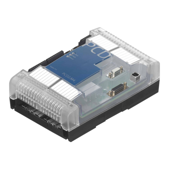
- Page 1 Manual PCD2.M4160, PCD2.M4560 User Manual Document 27-648 │ Edition ENG05 │ 2018-05-16...
-
Page 2: Table Of Contents
Power supply LED behaviour Run / Stop button I/O Bus slots and I/O extension port PCD2.M4160 ..................8-1 PCD2.M4560 ..................8-1 Data retention, Real time clock and battery module slot Usage of optional battery module ............9-1 User program data ................9-1 Digital interruptive inputs 10.1... - Page 3 Contents Saia-Burgess Controls AG PCD2.M4x60 Watchdog relay Communication ports 12.1 Baudrates ....................12-1 12.2 Slot A (Port #1) terminal block X5 ............12-2 12.2.1 RS-485/RS-422 PCD7.F110S Serial Interface Module ..........12-3 12.2.2 RS-232 up to 115 kBit/s, suitable for Modem Connection PCD7.F121S Serial Interface Module ..........
-
Page 4: Document History
Contents Saia-Burgess Controls AG PCD2.M4x60 Document History Version Changes Published Comments ENG01 2015-10-20 2015-10-26 First edition ENG02 2016-08-17 2016-08-17 - Power supply - Mounting with screws and DIN-rails ENG03 2016-09-01 2016-09-02 - New pictures for mounting with screws ENG04 2016-12-12 - Restrictions on communication port Slot ‘A’... -
Page 5: Graphical Overview
Graphical Overview The graphical overview shows some of the main topics covered in the Operating Manual of the PCD2.M4160 and PCD2.M4560. By clicking on the highlighted components and/or connections, you can jump directly to the corresponding chapter in the document. -
Page 6: Important Notes
PCD controllers include simple, built-in protection features. However, secure operation on the internet is only ensured if external routers are used with a firewall and encrypted VPN connections. For more information, please refer to our support site: www.sbc-support.com/security User Manual PCD2.M4x60 │ Document 27-648 │ Edition ENG 0 5 │ 2018-05-16... -
Page 7: Versions Overview
Versions overview Saia-Burgess Controls AG General Technical Details Versions overview PCD2.M4160 PCD2.M4560 Number of onboard digital inputs 4 digital inputs (24 V, configurable: Normal, Interrupt, Counter) Number of digital inputs/outputs in the base unit Or I/O module slots in the base unit Number of digital inputs/outputs with –... - Page 8 Power consumption Typ. 15 W with 64 I/O Load capacity 5 V/ +V intern max. 800 mA/250 mA Order details PCD2.M4160 PCD2 processor unit with Ethernet-TCP/IP, 512 kB program memory, 64 I/O PCD2.M4560 PCD2 processor unit with Ethernet-TCP/IP, 2 MB program memory, 1023 I/O...
-
Page 9: System Overview
System overview Saia-Burgess Controls AG On-board System overview I/O 0 I/O 1 I/O 3 I/O 2 PCD2.M4560 X1 – USB Device USB device 1.1 on type ‘B’ connector. User Manual PCD2.M4x60 │ Document 27-648 │ Edition ENG 0 5 │ 2018-05-16... -
Page 10: X2 - Isolated Rs-485 / Mpi
System overview Saia-Burgess Controls AG On-board X2 – Isolated RS-485 / MPI SUBD 9p connector S-Net / M PI / R S-485 D-Sub signal Explanation PGND 0 V of 24 V supply RxD/TxD-P ) B (red) Receive / t ransmit data positive RTS/CNTR-P Control signal for repeater (direction control) -
Page 11: X5 - Communication Port Slot 'A
System overview Saia-Burgess Controls AG On-board X5 – Communication port Slot ‘A’ PCD7.F121S PCD7.F110S PCD7.F180S PCD7.F150S PCD7.W600 1)2)3) 3)4) RS-232 RS-485 RS-422 Belimo RS-485, isol. 4xAO (0..+10 V) PGND PGND PGND PGND PGND PGND Rx-Tx Rx-Tx /Rx-/Tx „MFT“ /Rx-/Tx „IN“ PGND PGND PGND... -
Page 12: M1 - Memory Slot
System overview Saia-Burgess Controls AG On-board M1 – Memory Slot Slot for memory modules like PCD7.R610 for example. 4.10 BAT – Battery module slot Slot for PCD3 battery module. User Manual PCD2.M4x60 │ Document 27-648 │ Edition ENG 0 5 │ 2018-05-16... -
Page 13: Power Supply
Power supply Saia-Burgess Controls AG Power supply Supply voltage: 24 VDC -20% .. +25% Power consumption: Typically 15 W Capacity of internal 5V / V+ bus: 800 mA / 250 mA Connection terminals PCD2.M4x60 – – – 24 VDC Controller –... -
Page 14: Led Behaviour
LED behaviour Saia-Burgess Controls AG LED behaviour Three LEDs (green, red and yellow) show the possible operating statuses of the CPU as set out in the following table: Meaning Stop Error(s) Key: ● Form LED off Colour green yellow ● LED on ●... -
Page 15: Run / Stop Button
Run / Stop button Saia-Burgess Controls AG Requirements │ General Information Run / Stop button A push button is placed near the USB connector (X1). The operating mode can be changed during operation or during power-up. If the button is pressed in Run mode for longer than ½ second and less than 3 seconds, the controller switches to Stop mode and vice versa. -
Page 16: O Bus Slots And I/O Extension Port
I/O Bus slots and I/O extension port Saia-Burgess Controls AG PCD2.M4160 | PCD2.M4560 I/O Bus slots and I/O extension port PCD2.M4160 Four I/O Slots available in the PCD, addresses from 0 to 63. The communication modules (PCD2.Fxxx) or memory modules (PCD2.Rxxxx) can be connected in slots 0 or 1, but not in slots 2 or 3. -
Page 17: Data Retention, Real Time Clock And Battery Module Slot
Data retention Saia-Burgess Controls AG PCD2.M4160 | PCD2.M4560 Data retention, Real time clock and battery module slot Usage of optional battery module The slot for the PCD3 battery module will be unused for the most of applications. This option will be used only for customers they need to keep the real time clock up to date when the system stays unpowered more than 10 days. -
Page 18: Digital Interruptive Inputs
Interrupts Saia-Burgess Controls AG IX0 and IX1 Digital interruptive inputs Digital inputs respecting standard IEC 61131-2: Voltage input lower than 5V is considered as state “low” and voltage higher than 15V is considered as state “high”. Maximum input voltage = 30V. 10.1 Usage in normal digital inputs To use the digital inputs as normal inputs, choose the mode “Input”... -
Page 19: Onboard Counter
Interrupts Saia-Burgess Controls AG IX0 and IX1 10.3 Onboard Counter 10.3.1 Introduction The four Interrupt Inputs can be used as two independent On board Counters. This On board Counter is counting independent of the CPU Cycle. On the PCD1.M22_ the Onboard Interrupts and the Onboard Counter are using the same Inputs. -
Page 20: Function Description
Interrupts Saia-Burgess Controls AG IX0 and IX1 10.3.2 Function Description 10.3.2.1 Function Block Diagram Start Count/Rotate Input IX1 Clock PED 6500 PAD 6500 Counter Input IX0 Call XOB *(–1) Comparator Clock/Direction Reference value Number Info Configurable Parameters with SFC Call 10.3.2.2 Function Description To configure, to start and stop the Onboard Counter there exist a system call... -
Page 21: Counter Mode Description
Interrupts Saia-Burgess Controls AG IX0 and IX1 10.3.2.3 Counter Mode Description The Counter Mode is confugured in the IO-Configuration (On Board IO’s Inputs / Interrupts / Counter / Watchdog ) X1 Encoding In this mode, the counter is set on every positive edge of A and counts up or down depending on the B state. -
Page 22: System Function Parameters
Interrupts Saia-Burgess Controls AG IX0 and IX1 10.3.2.4 System Function Parameters With the System Function Library Number 17 Function Number 1 it is possible to start / stop and Configure the OnBoard Counter. The following table displays the Parameters Parameter Declaration Type Range Description... -
Page 23: Watchdog Relay
Watchdog Saia-Burgess Controls AG Watchdog relay PCD2.M4_ CPUs have a hardware watchdog as standard equipment. The watch- dog relay is at Pins 5 and 6 at Plug X4. Technical data Number of outputs 1× relay switching contact Function Watchdog function or user output (selectable) Max. -
Page 24: Communication Ports
Communication ports Saia-Burgess Controls AG Communication ports 12.1 Baudrates Baudrate Port 0 Port 1 Isolated RS485 RS485 on Slot ‘A’ Port 2 Port 10 board free protocol Profi S-Net S-Bus – – – – – – 1’200 – 2’400 – 4’800 –... -
Page 25: Slot A (Port #1) Terminal Block X5
Communication ports Saia-Burgess Controls AG 12.2 Slot A (Port #1) terminal block X5 Only PCD7.F1xxs modules are supported on the PCD2.M4x60. Slot A Terminal block X2 (connection terminals for Slot A) Older interface modules without “S” at the end of the product designation (e.g. -
Page 26: Rs-485/Rs-422
Communication ports Saia-Burgess Controls AG 12.2.1 RS-485/RS-422 PCD7.F110S Serial Interface Module Termination resistors can be connected (CLOSED) or disconnected (OPEN) with slide switchs. PCD7.F110S RS-485 termination Close, terminated, closed Slide Open, not terminated, open (factory setting) Slide Plug assignment: PCD2.M4x60 RS-485 peripheral Terminal Block... -
Page 27: Pcd7.F121S Serial Interface Module
Communication ports Saia-Burgess Controls AG 12.2.2 RS-232 up to 115 kBit/s, suitable for Modem Connection PCD7.F121S Serial Interface Module PCD7.F121S HW version Restrictions PCD2.M4x60 rev. A The signal "DCD" for modem communication is not supported. rev. B - Issue with "DTR" signal, RS-232 full protocoll with handshake on DTR-DSR-signals not supported. -
Page 28: Pcd7.F150S Serial Interface Module
Communication ports Saia-Burgess Controls AG 12.2.3 RS-485 electrical isolation PCD7.F150S Serial Interface Module Electrical isolation is achieved with three optocouplers and a DC/DC converter. Data signals are protected against overvoltage with an anti-surge diode (10 V). Termination resistors can be connected (CLOSED) or disconnected (OPEN) with slide switchs. -
Page 29: Belimo Mp-Bus
Communication ports Saia-Burgess Controls AG 12.2.4 Belimo MP-Bus PCD7.F180S Serial Interface Module Up to 8 actuators and sensors can be connected. PCD7.F180S Cabling PCD2.M4x60 : PCD2.M4x60 Belimo Terminal Block Bus cable PGND ´MFT´ ´IN´ PGND 24 VDC 24 VDC Cabling MP-Bus device 10 PGND Earth connection, MP string 11 MP Multi Point... -
Page 30: Dimensions
Dimensions Saia-Burgess Controls AG Dimensions Halt Error I/O BUS PCD2.M4_ Supply 24V 13-1 User Manual PCD2.M4x60 │ Document 27-648 │ Edition ENG 0 5 │ 2018-05-16... -
Page 31: Mounting
Mounting Saia-Burgess Controls AG PCD2.M4160 | PCD2.M4560 Mounting There are 2 different types of installation: mounted with screws snapped on 2 DIN rails 14-1 User Manual PCD2.M4x60 │ Document 27-648 │ Edition ENG 0 5 │ 2018-05-16... -
Page 32: Mounting With Screws
Mounting Saia-Burgess Controls AG Mounting with screws 14.1 Mounting with screws Screw diameter: less than Ø 4.9 Screw head diameter: less than Ø 8.0 125 mm 14-2 User Manual PCD2.M4x60 │ Document 27-648 │ Edition ENG 0 5 │ 2018-05-16... -
Page 33: Mounting The Pcd2.M4X60
Mounting Saia-Burgess Controls AG Mounting with screws 14.1.1 Mounting the PCD2.M4x60: Step 1 Step 2 Step 3 Fit the base plate over the screw Slide bottom Tighten the screws heads and press gently to the wall panel downwards Step 4 Fixed Snap lid onto base plate 14.1.2... -
Page 34: Din Rail Mounting
Mounting Saia-Burgess Controls AG DIN rail mounting 14.2 DIN rail mounting 14-4 User Manual PCD2.M4x60 │ Document 27-648 │ Edition ENG 0 5 │ 2018-05-16... -
Page 35: Mounting The Pcd2.M4X60
Mounting Saia-Burgess Controls AG DIN rail mounting 14.2.1 Mounting the PCD2.M4x60: Step 1 Step 2 Fixed Press the bottom of the Now press the upper half module to the wall and towards of the wall until it snaps slide it slowly upwards until it stops at the lower DIN rail 14.2.2... -
Page 36: A Annex
Annex Saia-Burgess Controls AG Icons Annex Icons In manuals, this symbol refers the reader to further information in this manual or other manuals or technical information documents. As a rule there is no direct link to such documents. This symbol warns the reader of the risk to components from electrostatic discharges caused by touch. -
Page 37: Contact
Email support: ......support@saia-pcd.com upportsite: ......www.sbc-support.com SBC site: ........ www.saia-pcd.com International Represetatives & SBC Sales Companies: ..www.saia-pcd.com/contact Postal address for returns from customers of the Swiss Sales office Saia-Burgess Controls AG Service Après-Vente Bahnhofstrasse 18 3280 Murten, Switzerland...
Need help?
Do you have a question about the PCD2.M4160 and is the answer not in the manual?
Questions and answers