Table of Contents
Advertisement
Quick Links
AVR-IoT Wx Hardware User Guide
Preface
Important: This document is applicable for two different products; AVR-IoT WG (AC164160) and AVR-
IoT WA (EV15R70A). Both variants are referred to as AVR-IoT Wx in this document, and both products
have identical hardware. AVR-IoT WG is preconfigured to send data through Google Cloud IoT Core, and
AVR-IoT WA is preconfigured to send data through Amazon Web Services (AWS). Both products can be
reconfigured to send data to different cloud providers.
Introduction
The AVR-IoT Wx Development Board is a small and easily expandable demonstration and development platform for
IoT solutions, based on the AVR
that the design of a typical IoT application can be simplified by partitioning the problem into three blocks:
•
Smart - represented by the
•
Secure - represented by the
•
Connected - represented by the
The AVR-IoT Wx Development Board features the following elements:
•
The on-board debugger (PKOB nano) supplies full programming and debugging support through Atmel Studio/
MPLAB X IDE. It also provides access to a serial port interface (serial to USB bridge) and two logic analyzer
channels (debug GPIO).
•
The on-board debugger enumerates on the PC as a mass storage interface device for easy 'drag and drop'
programming, Wi-Fi configuration, and full access to the microcontroller application Command Line Interface
(CLI)
™
•
A mikroBUS
socket allows for the ability to expand the board capabilities with the selection from 450+ sensors
and actuators options offered by MikroElektronika (www.mikroe.com) via a growing portfolio of Click boards
•
A light sensor used to demonstrate published data
•
Microchip
MCP9808
high-accuracy temperature sensor used to demonstrate published data
•
Microchip
MCP73871
©
2020 Microchip Technology Inc.
AVR-IoT Wx Hardware User
®
microcontroller architecture using Wi-Fi
ATmega4808
microcontroller
ATECC608A
secure element
ATWINC1510
Wi-Fi controller module
Li-Ion/LiPo battery charger with power path management
®
technology. It is designed to demonstrate
User Guide
Guide
™
DS50002805B-page 1
Advertisement
Table of Contents

Related Manuals for Microchip Technology AVR-IoT Wx


Summary of Contents for Microchip Technology AVR-IoT Wx
-
Page 1: Preface
Important: This document is applicable for two different products; AVR-IoT WG (AC164160) and AVR- IoT WA (EV15R70A). Both variants are referred to as AVR-IoT Wx in this document, and both products have identical hardware. AVR-IoT WG is preconfigured to send data through Google Cloud IoT Core, and AVR-IoT WA is preconfigured to send data through Amazon Web Services (AWS). - Page 2 AVR-IoT Wx Hardware User Guide ® • MPLAB X IDE Atmel Studio - Software to discover, configure, develop, program, and debug Microchip microcontrollers. • Application Code on GitHub - Get started with application code. • AVR-IoT WG website - Find schematics, design files, and purchase the board. Set up for Google Cloud IoT Core.
-
Page 3: Table Of Contents
AVR-IoT Wx Hardware User Guide Table of Contents Preface................................1 Introduction............................. 5 1.1. Features............................5 1.2. Board Overview..........................5 Getting Started............................7 2.1. Quick Start............................7 2.2. Design Documentation and Relevant Links................. 7 Application User Guide........................... 8 Hardware User Guide..........................9 4.1. - Page 4 AVR-IoT Wx Hardware User Guide Worldwide Sales and Service........................33 User Guide DS50002805B-page 4 © 2020 Microchip Technology Inc.
-
Page 5: Introduction
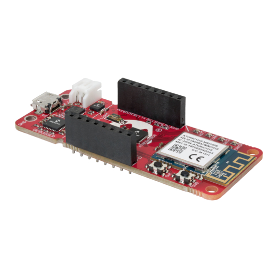
Fixed 3.3V Board Overview The AVR-IoT Wx development board is a hardware platform to evaluate and develop IoT solutions with the Microchip ATmega4808 AVR microcontroller, ATECC608A secure element, and WINC1510 Wi-Fi controller module. The preprogrammed demo application publishes data from the on-board light and temperature sensor read by the ATmega4808 every second to the cloud. - Page 6 AVR-IoT Wx Hardware User Guide Introduction AVR-Io T WG De ve lo pme nt Bo ard Pino ut Figure 1-1. AVR-IoT Wx Development Board Overview Charg e S tatus LEDs Mic ro US B Co nne c to r LiPo Co nne c to r...
-
Page 7: Getting Started
The board will now connect to your Wi-Fi network and send data to the website opened in step 2 through a cloud provider. Design Documentation and Relevant Links The following list contains links to the most relevant documents and software for the AVR-IoT Wx. • AVR-IoT WG website - Find schematics, design files, and purchase the board. -
Page 8: Application User Guide
Setup for Different Cloud Accounts Any AVR-IoT Wx kit can be reprovisioned to publish data to either Microchips sandbox account at Amazon Web Services, Microchips sandbox account at Google Cloud IoT Core, or to a personal account. Download the IoT Provisioning Tool package, compatible with Windows, Mac and Linux to get started: https:// www.microchip.com/mymicrochip/filehandler.aspx?ddocname=en1001525. -
Page 9: Hardware User Guide
A Data Gateway Interface (DGI) for code instrumentation with logic analyzer channels (debug GPIO) to visualize program flow The on-board debugger controls a Power and Status LED (marked PS) on the AVR-IoT Wx Board. The table below shows how the LED is controlled in different operation modes. - Page 10 AVR-IoT Wx Hardware User Guide Hardware User Guide 4.1.2.1 Overview The on-board debugger implements a composite USB device that includes a standard Communications Device Class (CDC) interface, which appears on the host as a virtual serial port. The CDC can be used to stream arbitrary data in both directions between the host computer and the target: All characters sent through the virtual serial port on the host computer will be transmitted as UART on the debugger’s CDC TX pin, and UART characters captured on the...
- Page 11 AVR-IoT Wx Hardware User Guide Hardware User Guide • Parity: Can be odd, even, or none. • Hardware flow control: Not supported. • Stop bits: One or two bits are supported. 4.1.2.4 Signaling During USB enumeration, the host OS will start both communication and data pipes of the CDC interface. At this point, it is possible to set and read back the baud rate and other UART parameters of the CDC, but data sending and receiving will not be enabled.
- Page 12 AUTORUN.ICO – icon file for the Microchip logo • AUTORUN.INF – system file required for Windows Explorer to show the icon file • CLICK-ME.HTM – redirect to the AVR-IoT Wx web demo application • KIT-INFO.HTM – redirect to the development board website •...
- Page 13 GPIO data. It is available as a plug-in for MPLAB X IDE or a stand-alone application that can be used in parallel with Atmel Studio/MPLAB X IDE. Although DGI encompasses several physical data interfaces, the AVR-IoT Wx implementation includes logic analyzer channels: •...
-
Page 14: On-Board Debugger Connections
AVR-IoT Wx Hardware User Guide Hardware User Guide Figure 4-2. Monitoring Debug GPIO with MPLAB Data Visualizer Debug GPIO channels are timestamped, so the resolution of DGI GPIO events is determined by the resolution of the DGI timestamp module. Important: Although bursts of higher-frequency signals can be captured, the useful frequency range of signals for which debug GPIO can be used is up to about 2 kHz. -
Page 15: Power
4.3.3 Hardware Modifications On the bottom side of the AVR-IoT Wx board there are two cut-straps, as shown in the figure below. These are intended for current measurement purposes. Do not leave these unconnected as the microcontrollers might get powered through the I/O’s. -
Page 16: Peripherals
Socket AVR-IoT Wx features a mikroBUS socket for expanding the functionality of the development board using MikroElektronika Click Boards and other mikroBUS add-on boards. The socket is populated with two 1x8 2.54 mm pitch female headers and is ready to mount add-on boards. - Page 17 AVR-IoT Wx Hardware User Guide Hardware User Guide ...continued ™ mikroBUS Socket Pin ATmega4808 Pin Function Shared Functionality GPIO — UART1 RX — UART1 TX — TWI0 SCL MCP9808 ATECC608A TWI0 SDA MCP9808 ATECC608A — VCC_MUX , MCP73871 — output Ground —...
- Page 18 The ATECC608A CryptoAuthentication device on the AVR-IoT Wx board is used to authenticate the hardware with cloud providers to uniquely identify every board. Note: 7-bit I C address: 0x58.
- Page 19 ADC AIN5 — 4.4.7 There are four LEDs available on the AVR-IoT Wx board that can be controlled with PWM or GPIO. The LEDs can be activated by driving the connected I/O line to GND. Table 4-10. LED Connections ATmega4808 Pin...
-
Page 20: Regulatory Approval
AVR-IoT Wx Hardware User Guide Regulatory Approval Regulatory Approval The AVR-IoT Wx development board has been testedby the following standards: Emission: • FCC Part 15 subpart B:2018 (Class B) • EN55032:2015 (Class B) Immunity: • EN55024:2010+A1:2015 • EN61000-4-2:2009 (contact: level 2 (±4 kV), air: level3 (±8 kV)) •... -
Page 21: Taiwan
AVR-IoT Wx Hardware User Guide Regulatory Approval Le présent appareil est conforme aux CNR d'Industrie Canada applicables aux appareils radio exempts de licence. L'exploitation est autorisée aux deux conditions suivantes: (1) l'appareil ne doit pas produire de brouillage, et (2) l'utilisateur de l'appareil doit accepter tout brouillage radioélectrique subi, même si le brouillage est susceptible d'en compromettre le fonctionnement. -
Page 22: Hardware Revision History And Known Issues
Identifying Product ID and Revision The revision and product identifier of the AVR-IoT Wx boards can be found in two ways: Either by utilizing the Atmel Studio/MPLAB X IDE Kit Window or by looking at the sticker on the bottom side of the PCB. -
Page 23: Avr-Iot Wa
AVR-IoT Wx Hardware User Guide Hardware Revision History and Known Issues New PCB revision 4, fixing issues with the MCP73871 Li-Ion/LiPo charger connections. 6.2.4 Revision 6 Revision 6 is the early adopter revision. It does not have the MCP73871 Li-Ion/LiPo charger or battery connector components mounted, and can only be powered through USB. -
Page 24: Document Revision History
AVR-IoT Wx Hardware User Guide Document Revision History Document Revision History Doc. rev. Date Comment 03/2020 Updated with AVR-IoT WG revsion 9, updated with information about AVR-IoT 10/2018 Initial document release. User Guide DS50002805B-page 24 © 2020 Microchip Technology Inc. -
Page 25: Appendix
AVR-IoT Wx Hardware User Guide Appendix Appendix Schematic Figure 8-1. AVR-IoT Wx Schematic User Guide DS50002805B-page 25 © 2020 Microchip Technology Inc. - Page 26 AVR-IoT Wx Hardware User Guide Appendix User Guide DS50002805B-page 26 © 2020 Microchip Technology Inc.
-
Page 27: Assembly Drawing
AVR-IoT Wx Hardware User Guide Appendix Assembly Drawing Figure 8-2. AVR-IoT Wx Assembly Drawing Top ® Figure 8-3. AVR-IoT Wx Assembly Drawing Bottom C -IoT Mechanical Drawings The figures below show the board’s mechanical drawing and connector placement. Figure 8-4. Mechanical Drawing 16,46mm... -
Page 28: Getting Started With Iar
GCC. Programming and ™ debugging of AVR-IoT Wx is supported in IAR Embedded Workbench for AVR using the Atmel-ICE interface. Some initial settings must be set up in the project to get the programming and debugging to work. - Page 29 AVR-IoT Wx Hardware User Guide Appendix Figure 8-6. Select Target Device Figure 8-7. Select Debugger User Guide DS50002805B-page 29 © 2020 Microchip Technology Inc.
- Page 30 AVR-IoT Wx Hardware User Guide Appendix Figure 8-8. Configure Interface User Guide DS50002805B-page 30 © 2020 Microchip Technology Inc.
-
Page 31: The Microchip Website
AVR-IoT Wx Hardware User Guide The Microchip Website Microchip provides online support via our website at http://www.microchip.com/. This website is used to make files and information easily available to customers. Some of the content available includes: • Product Support – Data sheets and errata, application notes and sample programs, design resources, user’s guides and hardware support documents, latest software releases and archived software •... -
Page 32: Trademarks
The Adaptec logo, Frequency on Demand, Silicon Storage Technology, and Symmcom are registered trademarks of Microchip Technology Inc. in other countries. GestIC is a registered trademark of Microchip Technology Germany II GmbH & Co. KG, a subsidiary of Microchip Technology Inc., in other countries. - Page 33 New York, NY Tel: 46-31-704-60-40 Tel: 631-435-6000 Sweden - Stockholm San Jose, CA Tel: 46-8-5090-4654 Tel: 408-735-9110 UK - Wokingham Tel: 408-436-4270 Tel: 44-118-921-5800 Canada - Toronto Fax: 44-118-921-5820 Tel: 905-695-1980 Fax: 905-695-2078 User Guide DS50002805B-page 33 © 2020 Microchip Technology Inc.
Need help?
Do you have a question about the AVR-IoT Wx and is the answer not in the manual?
Questions and answers