Table of Contents
Advertisement
Quick Links
Preface
The AVR-BLE Development Board is a small and easily expandable demonstration and development platform for
®
Bluetooth
Low Energy (BLE) solutions based on the AVR
demonstrate that the design of a typical BLE application can be simplified by partitioning the task into three blocks:
•
Smart – represented by the ATmega3208 microcontroller
•
Secure – represented by the ATECC608A secure element
•
Connected – represented by the RN4870 BLE module
In addition, the AVR-BLE Development Board features the following elements:
•
The on-board debugger (PKoB nano) supplies full programming and debugging support through Atmel Studio/
®
Microchip MPLAB
X IDE. It also provides access to a serial port interface (serial to USB bridge) and two logic
analyzer channels (debug GPIO).
™
•
A mikroBUS
socket enables the ability to expand the board capabilities with the selection from 450+ sensors
and actuators options offered by MikroElektronika (www.mikroe.com) via a growing portfolio of Click board
©
2020 Microchip Technology Inc.
AVR-BLE Hardware User Guide
®
microcontroller architecture. It is designed to
User Guide
™
.
DS50002956A-page 1
Advertisement
Table of Contents

Related Manuals for Microchip Technology AVR-BLE


Summary of Contents for Microchip Technology AVR-BLE
-
Page 1: Preface
AVR-BLE Hardware User Guide Preface The AVR-BLE Development Board is a small and easily expandable demonstration and development platform for ® ® Bluetooth Low Energy (BLE) solutions based on the AVR microcontroller architecture. It is designed to demonstrate that the design of a typical BLE application can be simplified by partitioning the task into three blocks: •... -
Page 2: Table Of Contents
Assembly Drawing........................27 The Microchip Website..........................28 Product Change Notification Service......................28 Customer Support............................28 Microchip Devices Code Protection Feature....................28 Legal Notice..............................28 Trademarks..............................29 Quality Management System........................29 Worldwide Sales and Service........................30 User Guide DS50002956A-page 2 © 2020 Microchip Technology Inc. -
Page 3: Introduction
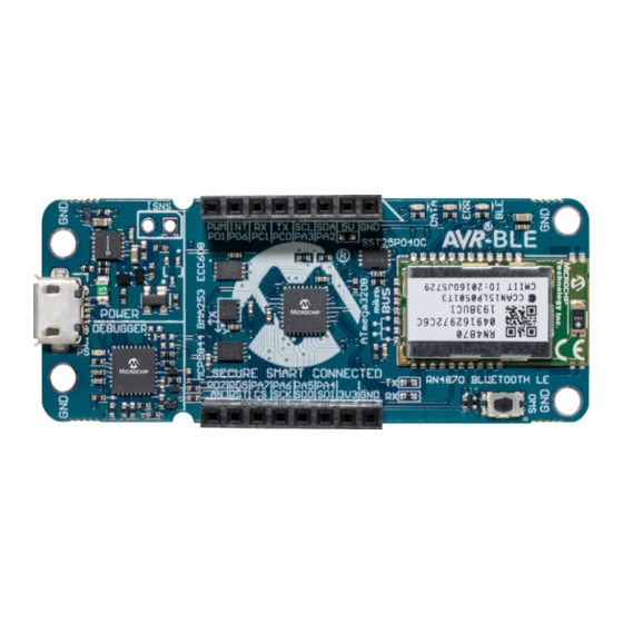
– Two logic analyzer channels (DGI GPIO) • USB or Battery Powered Board Overview The AVR-BLE development board is a hardware platform that is being used to evaluate the ATmega3208 AVR microcontroller and RN4870 BLE module. Figure 1-1. AVR-BLE Development Board Front Side Micro USB... - Page 4 Introduction Figure 1-2. AVR-BLE Development Board Back Side CR2032 Battery Holder Additional RN4870 GPIO User Guide DS50002956A-page 4 © 2020 Microchip Technology Inc.
- Page 5 Introduction Figure 1-3. AVR-BLE Quick Reference Overview User Guide DS50002956A-page 5 © 2020 Microchip Technology Inc.
-
Page 6: Getting Started
Connect a USB cable (Standard-A to Micro-B or Micro-AB) between the Windows, Mac or Linux device, and ® the debug USB port on the AVR-BLE. The board will be identified in the kit window in MPLAB X IDE. Explore, modify, and build off the source code. -
Page 7: Design Documentation And Relevant Links
Tip: The Kit Window can be opened in MPLAB X IDE through the menu bar Window > Kit Window Design Documentation and Relevant Links The following list contains links to the most relevant documents and software for the AVR-BLE Board: ® ®... -
Page 8: Hardware User Guide
A Data Gateway Interface (DGI) for code instrumentation with logic analyzer channels (debug GPIO) to visualize program flow The on-board debugger controls a Power and Status LED (marked PS) on the AVR-BLE Board. The table below shows how the LED is controlled in different operation modes. - Page 9 Baud rate: Must be in the range of 1200 bps to 500 kbps. Any baud rate outside this range will be set to the closest limit, without warning. Baud rate can be changed on-the-fly. • Character format: Only 8-bit characters are supported. User Guide DS50002956A-page 9 © 2020 Microchip Technology Inc.
- Page 10 64-byte frames, which are sent to the USB queue for transmission to the host when they are full. Incomplete frames are also pushed to the USB queue at approximately 100 ms intervals, triggered by USB start-of-frame tokens. Up to eight 64-byte frames can be active at any time. User Guide DS50002956A-page 10 © 2020 Microchip Technology Inc.
- Page 11 AUTORUN.ICO – icon file for the Microchip logo • AUTORUN.INF – system file required for Windows Explorer to show the icon file • CLICK-ME.HTM – redirect to the AVR-BLE web demo application • KIT-INFO.HTM – redirect to the development board website •...
- Page 12 X IDE or a stand-alone application that can be used ® in parallel with Atmel Studio/Microchip MPLAB X IDE. Although DGI encompasses several physical data interfaces, the AVR-BLE implementation includes logic analyzer channels: • Two debug GPIO channels (also known as DGI GPIO) 3.1.4.1...
-
Page 13: Power Supply
Current drawn from the USB port is limited to 500 mA by a PTC resettable fuse. Important: When powering the AVR-BLE board with a CR2032 battery, it is important to leave the ATmega3208 pins that connect to the CDC UART in Tri-State (Input) mode. This is to prevent the debugger from getting powered through its GPIO. -
Page 14: Low-Power Operation
Power to the ATmega3208 and its peripherals is connected from the on-board power supply through a 0Ω resistor (R301) in parallel with a 100-mil Current sense pin header footprint marked with “ISNS” in silkscreen (J301). To User Guide DS50002956A-page 14 © 2020 Microchip Technology Inc. -
Page 15: Peripherals
20 MHz and with 32 KB Flash, 4 KB SRAM, and 256 bytes of electrically erasable programmable read-only memory (EEPROM) in a 28- or 32-pin package. It uses the latest Core Independent Peripherals (CIPs) with low-power features, including Event System, accurate analog features, and advanced peripherals. User Guide DS50002956A-page 15 © 2020 Microchip Technology Inc. - Page 16 +3.3V VBUS The AVR-BLE board features a mikroBUS socket for expanding the functionality of the development board using MikroElektronika Click Boards and other mikroBUS add-on boards. The socket is populated with two 1x8 2.54 mm pitch female headers and is ready to mount add-on boards.
- Page 17 The module has one of its GPIO pins connected to an LED. By default, this will indicate connection status, but the user can configure it for a number of other functions. Many of the other RN4870 GPIO pins are available as pads around the label on the back side of the AVR-BLE board, as can be seen in Figure 1-2.
- Page 18 Microchip CryptoAuthentication products, the ATECC608A employs ultra-secure, hardware-based cryptographic key storage and cryptographic countermeasures that eliminate any potential backdoors linked to software weaknesses. The ATECC608A CryptoAuthentication device on the AVR-BLE board can be used to authenticate the board with other hardware for secure IoT communication.
- Page 19 Motion Triggered Interrupts: – New Data – Any Motion Detection – Single/Double Tap Sensing – Orientation Recognition – Flat Detection – Low/High-g Detection – Inactivity Detection • Operating Voltage Range: 1.62V to 3.6V User Guide DS50002956A-page 19 © 2020 Microchip Technology Inc.
- Page 20 LEDs There are two user LEDs available on the AVR-BLE board that can be controlled by either GPIO or PWM. In addition, there is one LED connected directly to the BLE module. The LEDs can be activated by driving their connected I/O lines to GND.
- Page 21 3.5.10 On-Board Debugger Implementation AVR-BLE features an on-board debugger that can be used to program and debug the ATmega3208 using UPDI. The on-board debugger also includes a virtual serial port (CDC) interface over UART and debug GPIO. Atmel Studio/ ®...
-
Page 22: Hardware Revision History And Known Issues
Identifying Product ID and Revision The revision and product identifier of the AVR-BLE Board can be found in two ways: Either by utilizing the Atmel ® Studio/Microchip MPLAB X IDE Kit Window or by looking at the sticker on the bottom side of the PCB. -
Page 23: Document Revision History
Document Revision History Document Revision History Doc. rev. Date Comment 03/2020 Initial document release User Guide DS50002956A-page 23 © 2020 Microchip Technology Inc. -
Page 24: Appendix
Appendix Appendix Schematics Figure 6-1. AVR-BLE Target schematic User Guide DS50002956A-page 24 © 2020 Microchip Technology Inc. - Page 25 Appendix Figure 6-2. AVR-BLE Power Schematic User Guide DS50002956A-page 25 © 2020 Microchip Technology Inc.
- Page 26 Appendix Figure 6-3. AVR-BLE Debugger Schematic User Guide DS50002956A-page 26 © 2020 Microchip Technology Inc.
-
Page 27: Assembly Drawing
Appendix Assembly Drawing Figure 6-4. AVR-BLE Assembly Drawing Top ® C -BLE ® Figure 6-5. AVR-BLE Assembly Drawing Bottom User Guide DS50002956A-page 27 © 2020 Microchip Technology Inc. -
Page 28: The Microchip Website
Information contained in this publication regarding device applications and the like is provided only for your convenience and may be superseded by updates. It is your responsibility to ensure that your application meets with User Guide DS50002956A-page 28 © 2020 Microchip Technology Inc. -
Page 29: Trademarks
The Adaptec logo, Frequency on Demand, Silicon Storage Technology, and Symmcom are registered trademarks of Microchip Technology Inc. in other countries. GestIC is a registered trademark of Microchip Technology Germany II GmbH & Co. KG, a subsidiary of Microchip Technology Inc., in other countries. -
Page 30: Worldwide Sales And Service
New York, NY Tel: 46-31-704-60-40 Tel: 631-435-6000 Sweden - Stockholm San Jose, CA Tel: 46-8-5090-4654 Tel: 408-735-9110 UK - Wokingham Tel: 408-436-4270 Tel: 44-118-921-5800 Canada - Toronto Fax: 44-118-921-5820 Tel: 905-695-1980 Fax: 905-695-2078 User Guide DS50002956A-page 30 © 2020 Microchip Technology Inc.
Need help?
Do you have a question about the AVR-BLE and is the answer not in the manual?
Questions and answers