Table of Contents
Advertisement
Quick Links
AVR128DA48 Curiosity Nano User Guide
Preface
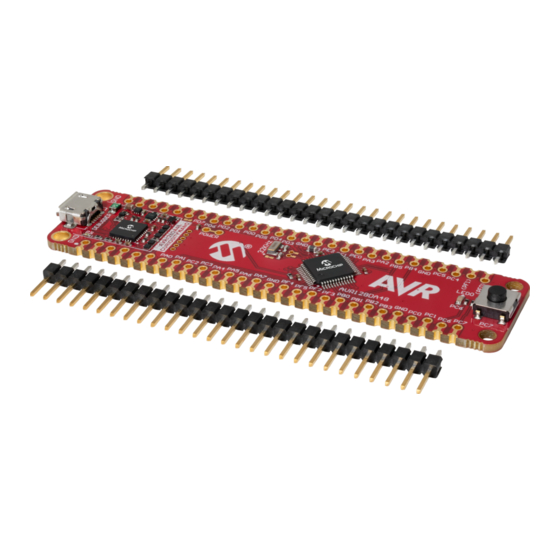
The AVR128DA48 Curiosity Nano Evaluation Kit is a hardware platform to evaluate microcontrollers in the AVR-DA
family. This board has the AVR128DA48 microcontroller (MCU) mounted.
Supported by Atmel Studio and Microchip MPLAB
provides easy access to the features of the AVR128DA48 to explore how to integrate the device into a custom
design.
The Curiosity Nano series of evaluation boards include an on-board debugger. No external tools are necessary to
program and debug the AVR128DA48.
®
•
MPLAB
X IDE
and
Atmel Studio
microcontrollers.
•
Code examples in Atmel START
application.
•
Code examples on GitHub
•
AVR128DA48 website
•
AVR128DA48 Curiosity Nano website
©
2020 Microchip Technology Inc.
AVR128DA48 Curiosity Nano
®
X Integrated Development Environments (IDEs), the board
- Software to discover, configure, develop, program, and debug Microchip
- Get started with code examples or generate drivers for a custom
- Get started with code examples.
- Find documentation, datasheets, sample, and purchase microcontrollers.
- Kit information, latest user guide and design documentation.
User Guide
DS50002971A-page 1
Advertisement
Table of Contents

Related Manuals for Microchip Technology AVR128DA48 Curiosity Nano


Summary of Contents for Microchip Technology AVR128DA48 Curiosity Nano
-
Page 1: Preface
AVR128DA48 Curiosity Nano AVR128DA48 Curiosity Nano User Guide Preface The AVR128DA48 Curiosity Nano Evaluation Kit is a hardware platform to evaluate microcontrollers in the AVR-DA family. This board has the AVR128DA48 microcontroller (MCU) mounted. ® Supported by Atmel Studio and Microchip MPLAB... -
Page 2: Table Of Contents
Hardware Modifications....................19 3.5.4. Connecting to External Microcontrollers..............20 3.6. Connecting External Debuggers....................21 Hardware User Guide........................... 24 4.1. Connectors..........................24 4.1.1. AVR128DA48 Curiosity Nano Pinout................24 4.1.2. Using Pin Headers.......................24 4.2. Peripherals..........................25 User Guide DS50002971A-page 2 © 2020 Microchip Technology Inc. - Page 3 AVR128DA48 Curiosity Nano 4.2.1. LED..........................25 4.2.2. Mechanical Switch....................... 25 4.2.3. Crystal..........................25 4.2.4. On-Board Debugger Implementation................26 4.2.4.1. On-Board Debugger Connections............. 26 Hardware Revision History and Known Issues..................27 5.1. Identifying Product ID and Revision................... 27 5.2. Revision 3...........................27 Document Revision History........................28 Appendix...............................
-
Page 4: Introduction
– 1.8-5.1V output voltage (limited by USB input voltage) – 500 mA maximum output current (limited by ambient temperature and output voltage) Kit Overview The Microchip AVR128DA48 Curiosity Nano Evaluation Kit is a hardware platform to evaluate the AVR128DA48 microcontroller. Figure 1-1. AVR128DA48 Curiosity Nano Evaluation Kit Overview... -
Page 5: Getting Started
Tip: The Kit Window can be opened in MPLAB X IDE through the menu bar Window > Kit Window. Design Documentation and Relevant Links The following list contains links to the most relevant documents and software for the AVR128DA48 Curiosity Nano Board: ®... - Page 6 Microchip development boards, ready to be adapted and extended. • AVR128DA48 Curiosity Nano website - Kit information, latest user guide and design documentation. • AVR128DA48 Curiosity Nano on microchipDIRECT - Purchase this kit on microchipDIRECT. User Guide DS50002971A-page 6 ©...
-
Page 7: Curiosity Nano
A Data Gateway Interface (DGI) for code instrumentation with logic analyzer channels (debug GPIO) to visualize program flow The on-board debugger controls a Power and Status LED (marked PS) on the AVR128DA48 Curiosity Nano Board. The table below shows how the LED is controlled in different operation modes. -
Page 8: Virtual Serial Port (Cdc)
AVR128DA48 Curiosity Nano Curiosity Nano Remember: Keep the debugger’s firmware up-to-date. Firmware upgrades are done automatically when ® using Atmel Studio/Microchip MPLAB X IDE. 3.1.2 Virtual Serial Port (CDC) The virtual serial port (CDC) is a general purpose serial bridge between a host PC and a target device. -
Page 9: Limitations
AVR128DA48 Curiosity Nano Curiosity Nano Info: For all operating systems: Be sure to use a terminal emulator that supports DTR signaling. See 3.1.2.4 Signaling. 3.1.2.3 Limitations Not all UART features are implemented in the on-board debugger CDC. The constraints are outlined here: •... -
Page 10: Mass Storage Device
AVR128DA48 Curiosity Nano Curiosity Nano USB-Level Framing Considerations Sending data from the host to the CDC can be done byte-wise or in blocks, which will be chunked into 64-byte USB frames. Each such frame will be queued up for sending to the debugger’s CDC TX pin. Transferring a small amount of data per frame can be inefficient, particularly at low baud rates, because the on-board debugger buffers frames and not bytes. -
Page 11: Fuse Bytes
AVR128DA48 Curiosity Nano Curiosity Nano Info: STATUS.TXT is dynamically updated by the on-board debugger. The contents may be cached by the OS and, therefore, do not reflect the correct status. 3.1.3.2 Fuse Bytes ® Fuse Bytes (AVR MCU Targets) When doing drag-and-drop programming, the debugger masks out fuse bits that attempt to disable Unified Program and Debug Interface (UPDI). -
Page 12: Data Gateway Interface (Dgi)
X IDE or a stand-alone application that can be used ® in parallel with Atmel Studio/Microchip MPLAB X IDE. Although DGI encompasses several physical data interfaces, the AVR128DA48 Curiosity Nano implementation includes logic analyzer channels: • Two debug GPIO channels (also known as DGI GPIO) 3.1.4.1... -
Page 13: Curiosity Nano Standard Pinout
AVR128DA48 Curiosity Nano Curiosity Nano Curiosity Nano Standard Pinout The 12 edge connections closest to the USB connector on Curiosity Nano boards have a standardized pinout. The program/debug pins have different functions depending on the target programming interface, as shown in the table and figure below. -
Page 14: Target Regulator
1.7V to 5.1V. Additional output voltage limits are configured in the debugger firmware to ensure that the output voltage never exceeds the hardware limits of the AVR128DA48 microcontroller. The voltage limits configured in the on-board debugger on AVR128DA48 Curiosity Nano are 1.8-5.1V. -
Page 15: External Supply
3.3.2 External Supply AVR128DA48 Curiosity Nano can be powered by an external voltage instead of the on-board target regulator. When the Voltage Off (VOFF) pin is shorted to ground (GND), the on-board debugger firmware disables the target regulator, and it is safe to apply an external voltage to the VTG pin. -
Page 16: Vbus Output Pin
VBUS Output Pin AVR128DA48 Curiosity Nano has a VBUS output pin that can be used to power external components that need a 5V supply. The VBUS output pin has a PTC fuse to protect the USB against short circuits. A side effect of the PTC fuse is a voltage drop on the VBUS output with higher current loads. -
Page 17: Low Power Measurement
AVR128DA48 Curiosity Nano Curiosity Nano Target Voltage is Different From Setting This can be caused by an externally applied voltage to the VTG pin, without setting the VOFF pin low. If the target voltage differ more than 100 mV over/under the voltage setting, it will be detected by the on-board debugger, and the internal voltage regulator will be shut down. -
Page 18: Programming External Microcontrollers
7.4 Disconnecting the On-board Debugger. Programming External Microcontrollers The on-board debugger on AVR128DA48 Curiosity Nano can be used to program and debug microcontrollers on external hardware. 3.5.1 Supported Devices All external AVR microcontrollers with the UPDI interface can be programmed and debugged with the on-board debugger with Atmel Studio. -
Page 19: Hardware Modifications
AVR128DA48 Curiosity Nano Curiosity Nano To program and debug a different microcontroller than what is mounted on the board, Atmel Studio must be configured to allow free selection of devices and programming interfaces. Navigate to Tools > Options through the menu system at the top of the application. -
Page 20: Connecting To External Microcontrollers
DBG3 is an open-drain connection and requires a pull-up resistor to function. AVR128DA48 Curiosity Nano has a pull-up resistor R200 connected to its #RESET signal (DBG3). The location of the pull-up resistor is shown in the 7.2 Assembly Drawing in the appendix. -
Page 21: Connecting External Debuggers
AVR128DA48 Curiosity Nano Curiosity Nano Figure 3-10. Curiosity Nano Standard Pinout PS LED VBUS VOFF CDC RX DBG3 DEBUGGER CDC TX DBG0 DBG1 DBG2 CURIOSITY NANO Table 3-4. Programming and Debugging Interfaces ™ Curiosity Nano Pin UPDI ICSP DBG0 UPDI DATA SWDIO... - Page 22 AVR128DA48 Curiosity Nano Curiosity Nano ™ ® Figure 3-11. Connecting the MPLAB PICkit 4 In-Circuit Debugger/Programmer to AVR128DA48 Curiosity Nano 1 = Unused MPLAB® PICkit™ 4 2 = V 3 = Ground 4 = PGD 5 = Unused 6 = Unused...
- Page 23 AVR128DA48 Curiosity Nano Curiosity Nano Figure 3-12. Connecting the Atmel-ICE to AVR128DA48 Curiosity Nano AVR® Atmel-ICE Ground 1 = Unused 6 = Unused 7 = Unused 2 = GND 3 = UPDI 8 = Unused 4 = VTG 9 = Unused...
-
Page 24: Hardware User Guide
Using Pin Headers The edge connector footprint on AVR128DA48 Curiosity Nano has a staggered design where each hole is shifted 8 mil (~0.2 mm) off-center. The hole shift allows the use of regular 100 mil pin headers on the board without soldering. -
Page 25: Peripherals
Peripherals 4.2.1 There is one yellow user LED available on the AVR128DA48 Curiosity Nano Board that can be controlled by either GPIO or PWM. The LED can be activated by driving the connected I/O line to GND. Table 4-1. LED Connection... -
Page 26: On-Board Debugger Implementation
Figure 4-2. Crystal Connection and Cut Straps 4.2.4 On-Board Debugger Implementation AVR128DA48 Curiosity Nano features an on-board debugger that can be used to program and debug the AVR128DA48 using UPDI. The on-board debugger also includes a virtual serial port (CDC) interface over UART and ®... -
Page 27: Hardware Revision History And Known Issues
Identifying Product ID and Revision The revision and product identifier of the AVR128DA48 Curiosity Nano Board can be found in two ways: Either by ® utilizing the Atmel Studio/Microchip MPLAB X IDE Kit Window or by looking at the sticker on the bottom side of the PCB. -
Page 28: Document Revision History
AVR128DA48 Curiosity Nano Document Revision History Document Revision History Doc. rev. Date Comment 03/2020 Initial document release. User Guide DS50002971A-page 28 © 2020 Microchip Technology Inc. -
Page 29: Appendix
AVR128DA48 Curiosity Nano Appendix Appendix Schematic Figure 7-1. AVR128DA48 Curiosity Nano Schematic User Guide DS50002971A-page 29 © 2020 Microchip Technology Inc. - Page 30 AVR128DA48 Curiosity Nano Appendix User Guide DS50002971A-page 30 © 2020 Microchip Technology Inc.
-
Page 31: Assembly Drawing
AVR128DA48 Curiosity Nano Appendix Assembly Drawing Figure 7-2. AVR128DA48 Curiosity Nano Assembly Drawing Top Figure 7-3. AVR128DA48 Curiosity Nano Assembly Drawing Bottom User Guide DS50002971A-page 31 © 2020 Microchip Technology Inc. -
Page 32: Curiosity Nano Base For Click Boards
AVR128DA48 Curiosity Nano Appendix ™ Curiosity Nano Base for Click boards Figure 7-4. AVR128DA48 Curiosity Nano Pinout Mapping VBUS DBG3 (PF1) VOFF DBG0 (PF0) CDCTX DBG2 CDCRX DBG1 User Guide DS50002971A-page 32 © 2020 Microchip Technology Inc. -
Page 33: Disconnecting The On-Board Debugger
AVR128DA48 Curiosity Nano Appendix Disconnecting the On-board Debugger The on-board debugger and level shifters can be completely disconnected from the AVR128DA48. The block diagram below shows all connections between the debugger and the AVR128DA48. The rounded boxes represent connections to the board edge. The signal names shown are also printed in silkscreen on the bottom side of the board. -
Page 34: Getting Started With Iar
GCC. Programming and ™ debugging of AVR128DA48 Curiosity Nano is supported in IAR Embedded Workbench for AVR using the Atmel-ICE interface. Some initial settings must be set up in the project to get the programming and debugging to work. - Page 35 AVR128DA48 Curiosity Nano Appendix Figure 7-7. Select Target Device Figure 7-8. Select Debugger User Guide DS50002971A-page 35 © 2020 Microchip Technology Inc.
- Page 36 AVR128DA48 Curiosity Nano Appendix Figure 7-9. Configure Interface User Guide DS50002971A-page 36 © 2020 Microchip Technology Inc.
-
Page 37: The Microchip Website
AVR128DA48 Curiosity Nano The Microchip Website Microchip provides online support via our website at http://www.microchip.com/. This website is used to make files and information easily available to customers. Some of the content available includes: • Product Support – Data sheets and errata, application notes and sample programs, design resources, user’s guides and hardware support documents, latest software releases and archived software •... -
Page 38: Trademarks
The Adaptec logo, Frequency on Demand, Silicon Storage Technology, and Symmcom are registered trademarks of Microchip Technology Inc. in other countries. GestIC is a registered trademark of Microchip Technology Germany II GmbH & Co. KG, a subsidiary of Microchip Technology Inc., in other countries. -
Page 39: Worldwide Sales And Service
New York, NY Tel: 46-31-704-60-40 Tel: 631-435-6000 Sweden - Stockholm San Jose, CA Tel: 46-8-5090-4654 Tel: 408-735-9110 UK - Wokingham Tel: 408-436-4270 Tel: 44-118-921-5800 Canada - Toronto Fax: 44-118-921-5820 Tel: 905-695-1980 Fax: 905-695-2078 User Guide DS50002971A-page 39 © 2020 Microchip Technology Inc.
Need help?
Do you have a question about the AVR128DA48 Curiosity Nano and is the answer not in the manual?
Questions and answers